EGS002纯正弦波逆变器驱动板配套后级功率板EGP1000W逆变器功率板
纯正弦波逆变器驱动板说明书

ELECTRONIC GIANT EGS001 用户手册纯正弦波逆变器驱动板EG8010 芯片测试板EGS001正弦波逆变器驱动板用户手册V1.2版本更新:V1.1:针脚定义中,将1HO、1LO和VS1的定义更改为右桥臂,将2HO、2LO和VS2的定义更改为左桥臂。
V1.2:更新原理图中短路保护电路。
1. 描述EGS001是一款专门用于单相纯正弦波逆变器的驱动板。
采用单相纯正弦波逆变器专用芯片EG8010为控制芯片,驱动芯片采用IR2110S。
驱动板上集成了电压、电流、温度保护功能,LED告警显示功能及风扇控制功能,并可通过跳线设置50/60Hz输出,软启动功能及死区大小。
EG8010是一款数字化的、功能很完善的自带死区控制的纯正弦波逆变发生器芯片,应用于DC-DC-AC两级功率变换架构或DC-AC单级工频变压器升压变换架构,外接12MHz晶体振荡器,能实现高精度、失真和谐波都很小的纯正弦波50Hz或60Hz逆变器专用芯片。
该芯片采用CMOS工艺,内部集成SPWM正弦发生器、死区时间控制电路、幅度因子乘法器、软启动电路、保护电路、RS232串行通讯接口和12832串行液晶驱动模块等功能。
2. 电路原理图EGS001驱动板原理图220V输出220V输出图2‐1. EGS001纯正弦波逆变器驱动板电路原理图3. 针脚及跳线3.1 EGS001正视图图3‐1. EGS001驱动板针脚定义3.2 针脚描述针脚序号针脚名称I/O描述1 IFB I 输出电流反馈输入端,引脚输入电压大于0.5V 时过流保护2 GND GND 接地端3 1LO O 右桥臂下管驱动门极输出4 GND GND 接地端5 VS1 O 右桥臂上下功率MOS 管中心点输出6 1HO O 右桥臂上管驱动门极输出7 GND GND 接地端8 2LO O 左桥臂下管驱动门极输出 9 VS2 O 左桥臂上下功率MOS 管中心点输出 10 2HO O 左桥臂上管驱动门极输出 11 GND GND 接地端12 +12V +12V +12V 电源电压输入,输入电压范围: 10V~15V 13 GND GND接地端 14 +5V +5V +5V 电源电压输入15 VFB I 输出电压反馈输入端,具体功能及电路请参照EG8010芯片手册17. FANCTR16. TFB15. VFB14. +5V13. GND12. +12V11. GND10. 2HO9. VS28. 2LO7. GND6. 1HO5. VS14. GND3. 1LO2. GND1. IFB16 TFB I 温度反馈输入端,引脚输入电压大于4.3V 时过热保护17 FANCTR O外接风扇控制,当T FB 引脚检测到温度高于45℃时,输出高电平“1”使风扇运行,运行后温度低于40℃时,输出低电平“0”使风扇停止工作3.3 跳线设置序号跳线名称标号设置说明JP1当JP1短路时,选择60Hz 输出 1 FRQSEL0JP5 当JP5短路时,选择50Hz 输出 JP2当JP2短路时,使能3秒软启动功能 2 SSTJP6 当JP6短路时,关闭软启动功能JP33 DT0JP7 JP44 DT1JP8当JP7和JP8同时短路时:死区时间为300ns 当JP3和JP8同时短路时:死区时间为500ns 当JP4和JP7同时短路时:死区时间为1.0us 当JP3和JP4同时短路时:死区时间为1.5us出厂时驱动板跳线默认设置为JP5、JP2、JP7、JP8短路,对应功能为50Hz 、3S 软启动、死区时间300nS ,用户可根据自己需求更改。
S-25-24

+10,-5%
±10%
±10%
±10%
启动、上升、保持时间
800ms,50ms,10ms/115VAC 300ms,50ms,80ms/230VAC满载
输入
输入电压范围
85~264 VAC 47~63 Hz;120~370VDC
交流输入电流
0.6 A/115 V 0.35A/ 230 V
-10℃~+60℃;20%~90 %RH
保存温度、湿度
-20℃~+85℃;10%~95 %RH
抗震性
10~500Hz,2G 10min./1周期,时长60分钟,各轴
安全
耐压性
输入输出间:3KVAC输入与地:1.5KVAC输出与地:0.5KVAC
绝缘电阻
输入输出间,输入与地,输出与地:100M Ohms/500VDC
输出
直流输出电压
5V
12V
15V
24V
输出电压容差(注3)
±2%
±1%
±1%
±1%
额定输出电流(1.1A
输出电流范围
0-5A
0-2.1A
0-1.7A
0-1.1A
输出功率
25W
25.2W
25.5W
26.4W
纹波及噪音(注2)
50mVp-p
100mVp-p
100mVp-p
100mVp-p
特点:
开关电源高效率,高可靠
全球适用AC输入电源
100%满负荷烧机测试
保护特性:短路/过载/过压
工作频率56KHz
空气冷却
1年保质期(UL认证产品)
尺寸: 99*97*36mm(L*W*H)
IPower-Plus系列高频纯正波逆变器用户手册说明书
Pure sine wave inverterUSER MANUALIP350-Plus,IP500-PlusIP1000-Plus, IP1500-PlusIP2000-Plus, IP3000-PlusIP4000-Plus, IP5000-PlusContentsImportant safety instructions 11 Overview 52 Appearance 73 Naming rule 114 Connection diagram 135 Remote meter 155.1 Appearance 155.2 Buttons 155.3 LCD interface 165.3.1 Real-time interface 165.3.2 Parameters setting 165.3.3 Power Saving Mode 165.3.4 Parameters user define 185.4 Error code 196 Installation 206.1 Attentions 206.2 Wire size and circuit breaker 206.3 Mounting 236.4 Rotate the LCD 287 Protections 298 Troubleshooting 339 Maintenance 3410 Specifications 35 Appendix 1 Disclaimers 44Important safety instructionsPlease reserve this manual for future review.This manual contains all safety, installation, and operation instructions for the IPower-Plus series high-frequency pure sine wave inverter ("inverter" referred to in this manual).1. Explanation of symbolsPlease read related literature accompanying the following symbols to efficiently use the product and ensure personal and property safety.The entire system should be installed by professional and technical personnel.2. Requirements for professional and technical personnel•Professionally trained;•Familiar with related safety specifications for the electrical system;•Read this manual carefully and master related safety cautions.3. Professional and technical personnel is allowed to do•Install the inverter to a specified location.•Conduct trial operations for the inverter.•Operate and maintain the inverter.4. Safety cautions before installation5. Safety cautions for mechanical installation6. Safety cautions for electrical connection7. Safety cautions for controller operation8. Dangerous operations which would cause electric arc, fire or explosion•Touch the wire end that hasn't been insulation treated and maybe electriferous.•Touch the wiring copper row, terminals, or internal modules of the inverter that may be electriferous. •The connection of the power cable is loose.•Screw or other spare parts inadvertently falls into the inverter.•Improper operations by untrained non-professional or technical personnel.9. Safety cautions for stopping the inverter•After the inverter stop running for five minutes, the internal conductive modules could be touched. •The inverter is allowed to restart after removing the faults, which affects safety performance. •There are no serviceable parts inside. If any maintenance service is required, please contact our service personnel.10. Safety cautions for inverter maintenance•It is recommended to check the inverter with testing equipment to ensure there is no voltage and current.•When conducting electrical connection and maintenance, post a temporary warning sign or put up barriers to prevent unrelated personnel from entering the electrical connection or maintenance area. •An improper operation of the inverter may cause personal injury or equipment damage.•Please wear an anti-static wrist strap to prevent static damage or avoid unnecessary contact with the circuit board.1 OverviewIPower-Plus is a new generation of pure sine wave inverter compatible with the lithium battery system. This new inverter adopts surge current suppression technology to effectively prevent the surge current from damaging the lithium battery cells and BMS (Battery Management System). Also, adopting the voltage and current double closed-loop control algorithm brings the inverter a faster response and better resistance to the load impact. The inverter selects key components with a high power density and long lifespan to provide a stable and reliable power guarantee. The optional communication solutions allow users to monitor the real-time status or change the parameters wherever.The inverter can be widely used in DC to AC areas, such as solar AC power system, vehicle system, RV power supply, security monitoring system, emergency lighting system, field power system, household power system, etc. With an excellent EMC (Electro Magnetic Compatibility) characteristic, the inverter is also suitable for occasions with high power quality requirements.Features:•Completely electrically isolated design for input and output•Full digital double closed-loop control•Excellent EMC characteristic, widely applied to higher quality power system•Advanced SPWM technology and pure sine wave output.•Input surge current suppression technology, applying to the lithium battery system•Outstanding load resistance to impact, applying to the air conditioners, washing machines, refrigerators, etc.•High power density and high-quality components to ensure the reliability•Output power factor up to 1•Low loss of zero loads and standby. Low THD (Total Harmonic Distortion). High conversion efficiency•Extensive protections: input reverse polarity/under voltage/over voltage, output overload/short circuit/overheating•Air cooling is controlled by temperature and load•Rotatable LCD meter to simplify the system wiring①•Friendly LCD meter to simply monitor and parameter configure①•Remote control by the phone Apps and PC software •Configurable output voltage, output frequency and baud rate②•Enable power saving mode(PSE) conveniently②•Charging mobile phones, DC fans, and other electrical equipment by the USB port•Support a variety of options by connecting with the RS485 com. port④•External switch contact design to allow remote control•EN/IEC62109, EN61000-6-1/3, RoHS, ETL and FCC approved①There is no LCD meter for the IP350-Plus series.②Configure the parameters via the local LCD meter (no including the IP350-Plus series),remote LCD meter, phone Apps, or PC software.③This function is unavailable for inverters with 48V input voltage.④There is no communication isolation design for inverters with 12V/24 input voltage. Thisfunction(communication isolation design) is just for inverters with 48V input voltage.2 Appearance∙IP350-xx-Plus✓Appearance with decorative cover is suitable for AC output of T-terminal / C-Chinese dual socket / N-North America✓Appearance without decorative cover is suitable for AC output of A-Australia / E-European / F-French / UK-United Kingdom∙IP500-xx-Plus✓Appearance with decorative cover is suitable for AC output of T-terminal / C-Chinese dual socket / N-North AmericaAppearance without decorative cover is suitable for AC output of A-Australia / E-European / F-French / UK-United Kingdom∙IP1000-xx-Plus∙IP1500-xx/IP2000-2x/IP2000-4x/IP3000-42-Plus∙IP2000-1x-Plus∙IP3000-1x-Plus∙IP3000-2x-Plus∙IP3000-41/IP4000-4x/IP5000-4x-Plus①Cooling fan∙Conditions to start the cooling fan:∙Conditions to stop the cooling fan:② The AC output port varies with different products. Please refer to chapter 3 Naming rule for thespecific supported types.③USB output port is not available for inverters with 48V input voltage.3 Naming ruleExplanations for the AC output port:★ GFCI outlets need to be tested after power-on to ensure proper operation.PreparationConnect a circuit breaker and an AC load (it is recommended to use a night light to observe the status conveniently) to the GFCI outlet. Turn on the inverter after confirming the wiring.Testing1) If the red LED is ON solid, it indicates that the GFCI outlet is damaged; please replace a new one. 2) If the LED is green ON after it flashes in red three times, connect the circuit breaker, and the night light will be turned on. Then, press the "TEST" button to observe the testing status:① The "TEST" button always pops up, and the night light keeps ON solid. It indicates that the GFCIwiring is an error; please correct the wrong wiring.② The "TEST" button goes down, while the "RESET" button pops up. The LED and the night light areturned off, indicating the GFCI outlet is normal (Note: Press the "RESET" button again to recover the load output).4 Connection diagramIP350-xx-Plus (take the “Appearance with decorative cover” as an example)IP500-xx-Plus(take the “Appearance with decorative cover” as an example)IP1000-xx/IP1500-xx/IP2000-2x/IP2000-4x/IP3000-42-PlusIP2000-1x-PlusIP3000-1x-PlusIP3000-2x/IP3000-41/IP4000-4x/IP5000-4x-Plus5 Remote meter5.1 AppearanceThe LCD display can be viewed clearly when the angle between the end-user's horizontal sight and the LCD screen is within 90°. If the angle exceeds 90°, the LCD display cannot be viewed clearly.5.2 Buttons+5.3 LCD interface5.3.1 Real-time interfaceClick orto browse the real-time interface.5.3.2 Parameters settingOperation:Step1: In the real-time interface, pressfor 2s to enter the parameter setting interface.Step2: Click or to select the parameter to be configured.Step3: Press for 2s to enter the configuration interface of the specified parameter.Step4: Click or to configure the parameter value.Step5: Press for 2s to confirm the configuration.Step6: Click + to exit the current interface.5.3.3 Power Saving ModeUsers can enable the power saving mode and set the PSI/PSO value by the/button (TheBattery voltage Load voltage Load currentLoad frequencyLoad powerminimum power step is 1VA).When the actual load power is lower than the PSI (the power to enter the power saving mode), the system will automatically switch to the power saving mode, and then the device output is turned on for 1s and turned off for 5s.When the actual load power exceeds the PSO (the power to exit the power saving mode), the inverter will automatically exit the power saving mode and resume work.1) Enable power saving mode (PSE)Step1: In the real-time interface of the remote meter, press and hold the button to enter the parameters setting interface.Step2: Click the or button to select the PSE parameter.Step3: Press and hold the button until the PSE parameter (OFF default) flashes.Step4: Click the or button to set the PSE status.•Select ON to enable the power saving mode.•Select OFF to disable the power saving mode.Step5: Press and hold the button to confirm.2)Set the power to exit the power saving mode (PSO)Step1: In the parameters setting interface, click the or button to select the PSO parameter.Step2: Press and hold the button until the PSO value flashes.Step3: Click the or button to set the PSO parameter.•Click the button to decrease the PSO value by 1.•Click the button to increase the PSO value by 1.•Press and hold the button to increase the PSO value by 10. After ten adding, the PSOvalue will increase by 100 each time. When the button is released, press and hold itagain to repeat the above operation (Note: The setting parameter cannot exceeds the userdefine, or it will back to the initial value to start the loop).Step4: Press and hold the button to confirm.3)Set the power to enter the power saving mode (PSI)Step1: In the parameters setting interface, click the orbutton to select the PSI parameter.Step2: Press and hold the button until the PSI value flashes. Step3: Click theorbutton to set the PSI parameter.• Click the button to decrease the PSI value by 1. • Click thebutton to increase the PSI value by 1.• Press and hold thebutton to increase the PSI value by 10. After ten adding, the PSIvalue will increase by 100 each time. When thebutton is released, press and hold itagain to repeat the above operation (Note: The setting parameter cannot exceeds the user define, or it will back to the initial value to start the loop).Step4: Press and hold thebutton to confirm.5.3.4 Parameters user define① After configuring the parameters marked with ①, the inverter will restart automatically. It willresume work according to the new parameter value.② Due to the length limit of the LCD displayed data, when the baud rate is set to 115200, the valuedisplayed on the LCD is 1152.③ For the parameter user defines, please refer to the input voltage rules in chapter 7 Protections.Otherwise, the parameter setting will not succeed.5.4 Error code6 Installation6.1 Attentions∙Read all the installation instructions carefully in the manual before installation.∙Be very careful when installing the batteries. When installing the open-type lead-acid battery, please wear eye protection and rinse with clean water in time for battery acid contact.∙Keep the battery away from any metal objects, which may cause a short circuit of the battery.∙Loose power connections and corroded wires may result in high heat that can melt wire insulation, burn surrounding materials, or even cause a fire. Ensure tight connections and secure cables with clamps to prevent them from swaying while moving the inverter.∙The DC input voltage must strictly be following the parameter table. Too high or too low DC input voltage will affect the inverter's normal operation and damage it. The surge voltage shall be less than 20V@12V system, less than 40V@24V system, and less than 80V@48V.∙Select the connection cables according to the current density of 3.5A/mm2 or less.∙Avoid direct sunlight and rain infiltration when installing it outdoor.∙After turn off the power switch, do not open or touch the internal component immediately. Related operations are performed after 10 minutes.∙Do not install the inverter in a harsh environment such as humid, salt spray, corrosion, greasy, flammable, explosive, or dust accumulation.∙The AC output is of high voltage, do not touch the wiring connection to avoid electric shock.∙To prevent injury, do not touch the fan while it is working.6.2 Wire size and circuit breakerThe wiring and installation methods must conform to the national and local electrical code requirements. Wire, terminals, and circuit breaker selection for battery★ According to the recommended battery wire size, 2 battery wires, connected in parallel, are necessary for IP1500-11-Plus, IP1500-12-Plus, IP2000-11-Plus, IP2000-12-Plus, IP3000-21-Plus, IP3000-22-Plus, and IP5000-42-Plus. 4battery wires, connected in parallel, are necessary forWire and circuit breaker selection for AC output6.3 MountingInstallation procedures:Step1: Professional personnel reads this manual carefully.Step 2: Determine the installation location and heat-dissipation spaceTo ensure natural thermal convection, you should install the inverter in a place with sufficient airflow and a minimum clearance of 150mm from the inverter's upper and lower edges.IP350-xx-Plus (take the “Appearance with decorative cover” as an example)IP500-xx-Plus (take the “Appearance with decorative cover” as an example)IP1000-xx/IP1500-xx/IP2000-2x/IP2000-4x/IP3000-42-PlusIP2000-1x-PlusIP3000-1x-PlusIP3000-2x/IP3000-41/IP4000-4x/IP5000-4x-PlusStep3: WiringWiring sequence (The following wiring sequence is illustrated in the appearance "IP2000-2x-Plus",wiring positions of other inverters. Please refer to chapter 2 Appearancefor reference.) 1. Ground connectionThe wire size for the ground connection must be thicker or equal to that for the AC output. Refer to chapter 6.2 Wire size and circuit breaker for detailed wire size.2. Battery connection3. AC loads connection1) Definition of the AC output portIt varies with different product models; please refer to the actual product. The following takes the AC terminal as an example.✦It is recommended to use a multi-stranded wire with a wire diameter of not more than 6mm2.✦Add solder to the connection point when selecting the multi-stranded wire and directly insert it into the corresponding port.✦Stop the inverter before removing the wiring. Then, insert a sharp tool into the small hole (on the top of the port) and pull out the wiring forcefully.2) Connect the AC load4. Optional accessories connection1) RS485 communication portRJ45 Pin Definition:2) Connect optional accessories5. USB port connection (USB port is not available for inverters with 48V input voltage.)Step 4:Power on the inverter⑴Connect the breaker at the inverter input terminal or the fuse at the battery end.⑵Turn on the inverter switch; the power indicator will be lighted on, indicating a normal AC output.⑶Turn on the AC loads one by one and check the inverter's running status and the loads.⑷If the fault indicator flashes red and the buzzer alarms after powering the inverter, pleaseimmediately turn off the load and the inverter. Clear the faults according to chapter 8 Troubleshooting.6.4 Rotate the LCD⑴Remove the screws of the LCD unit with a screwdriver, and rotate it 180°.⑵Secure the screws of the LCD unit to the inverter.7 Protections1) Input reverse polarity protectionWhen the DC input terminal's polarity is reversed, the indicator will not light up after power on. The buzzer will not sound, and the inverter will not work. The inverter will start to work normally after correcting the error wiring.2) Input voltage protection•The following rules must be followed when modifying the battery's input voltage parameters:A. Over voltage limiting voltage (16.2/32.2/64.4V) ≥Over voltage disconnect voltage ≥Overvoltage reconnect voltage +1V.B. Over voltage reconnect voltage ≥ Low voltage reconnect voltage.C. Low voltage reconnect voltage ≥ Low voltage disconnect voltage +1V.D. Low voltage disconnect voltage ≥ Low voltage limiting voltage (10.5/21/42V).•Detail status is shown as the following when the input voltage protection occurs.Buzzer beeps.3) Overload protectionThe red indicator slowly flashes..The red indicator slowly flashes..The red indicator slowly flashes.The red indicator slowly flashes.★ When the overload protection happens on IP2000-11-Plus, IP3000-21-Plus or IP3000-22-Plus, the AC output is shut down directly and cannot be recovered automatically..The red indicator slowly flashes..The red indicator slowly flashes.. The red indicator slowly flashes.The red indicator slowly flashes..4) Output short circuit protection5) Inverter over temperature protection8 Troubleshooting9 MaintenanceThe following inspections and maintenance tasks are recommended at least two times per year for good performance.•Make sure no block on airflow around the inverter. Clear up any dirt and fragments on the heat sink. •Check all the naked wires to ensure insulation is not damaged by sun exposure, frictional wear, dryness, insects or rats, etc.•Verify the indicator display is consistent with the actual operation.•Confirm that terminals have no corrosion, insulation damage, high temperature, burnt/discolored sign, and tighten terminal screws to the suggested torque.•Clear up dirt, nesting insects, and corrosion in time.•Check and confirm that the lightning arrester is in good condition. Replace a new one in time to avoid damaging the inverter and other equipment.10 Specifications35①It is measured in the condition of continuous output power and rated input voltage.②It means the max. output efficiency when the inverter is connected with different loads under the rated input voltage.36①It is measured in the condition of continuous output power and rated input voltage.②It means the max. output efficiency when the inverter is connected with different loads under the rated input voltage.37①It is measured in the condition of continuous output power and rated input voltage.②It means the max. output efficiency when the inverter is connected with different loads under the rated input voltage.①It is measured in the condition of continuous output power and rated input voltage.②It means the max. output efficiency when the inverter is connected with different loads under the rated input voltage. 220/230/240VAC output①It is measured in the condition of continuous output power and rated input voltage.②It means the max. output efficiency when the inverter is connected with different loads under the rated input voltage.①It is measured in the condition of continuous output power and rated input voltage.②It means the max. output efficiency when the inverter is connected with different loads under the rated input voltage.①It is measured in the condition of continuous output power and rated input voltage.②It means the max. output efficiency when the inverter is connected with different loads under the rated input voltage.①It is measured in the condition of continuous output power and rated input voltage.②It means the max. output efficiency when the inverter is connected with different loads under the rated input voltage.Appendix 1 DisclaimersThe warranty does not apply to the following conditions:•Damage is caused by improper use or an inappropriate environment (humid, salt spray, corrosion, greasy, flammable, explosive, dust accumulative, or other severe environments).•The actual current/voltage/power exceeds the limit value of the inverter.•Damage caused by working temperature exceeds the rated range.•Arc, fire, explosion, and other accidents are caused by failure to follow the inverter stickers or manual instructions.•Disassemble and repair the inverter without authorization.•Damage caused by force majeure.•Damage occurred during transportation or handling.•Before using precise instruments, such as a medical instrument, end-users must read the manual carefully and ensure the inverter's output power/output voltage is suitable. We are not responsible for the instrument damage caused by improper use.HUIZHOU EPEVER TECHNOLOGY CO., LTD. Tel: +86-752-3889706E-mail:***************。
EGS002纯正弦波逆变器驱动板配套后级功率板EGP1000W逆变器功率板

3.1
图3-1. EGP1000W逆变器功率板
3.2
3.2.1
EGP1000W逆变器功率板共有三个电源接口:功率电源接口(P3、P4)、驱动电源接口(P5)及风扇电源接口(P1)。
图3-2. EGP1000W逆变器功率底板电源管理部分原理图
功率电源(P3、P4)主要为逆变全桥供电,为逆变输出提供电能。工作在高频模式时,功率电源为一组高压直流电源,若要逆变输出交流220V,则输入的直流功率电压须在330V ~ 450V之间,高压直流电源可采用高频变压器DC-DC升压得到。工作在工频模式时,功率电源为一组低压直流电源,通常电压不大于60V,可采用电池组或其他直流电源供电。
4.
4.1
EGP1000W逆变器功率板共有两种工作模式:前级经高频变压器DC-DC升压后输入高压直流电至板上功率电源接口直接逆变输出模式(高频模式);直接输入低压直流电至板上功率电源接口逆变输出低压交流后经工频变压器升压输出高压交流(工频模式)。两种工作模式所用功率器件不同,用户可根据系统需求选型。工作在高频模式时,直流电压高,相同功率下电流小;工频模式时,直流电压低,相同功率下电流大。
VAC< VDC/1.414
此时,板上的交流输出接口(P8、P9)需要接工频变压器的低压线圈输入端口,变压器高压线圈输出端口并一个2.2uF的CBB滤波电容。使用工频变压器时,板上的LC滤波器件(L1、C13)可以省去,滤波电感(L1)用粗铜丝短路,滤波电容(C13)不焊。输出及反馈电路如同4-2所示。
工频模式时,驱动电源接口(P5)可以不接,使用功率电源经板上降压电路降压后为驱动电路供电,根据输入的功率电源电压不同,配置跳线;若不使用板上降压电路,也可在驱动电源接口(P5)外接+12V的电源为驱动电路供电。具体配置见表3-1.
eg1000ea规格书

eg1000ea规格书EG1000EA规格书一、产品简介EG1000EA是一款高性能的电动发电机组。
该发电机采用先进的技术和设计,拥有出色的功率输出和稳定性能。
它广泛应用于家庭、商业和工业领域,为用户提供可靠的电力支持。
二、主要特点1. 高效能:EG1000EA采用先进的发电机技术,具有高效的能源转换率,最大限度地提高发电效率。
2. 稳定性能:该发电机组配备了先进的稳压控制系统,能够自动调节输出电压,保证稳定的电力输出。
3. 低噪音:EG1000EA采用先进的降噪技术,噪音水平低于国家标准,为用户提供安静的使用环境。
4. 轻便便携:该发电机组采用轻量化设计,重量轻、体积小,便于携带和移动,适用于户外活动和临时用电需求。
三、技术参数1. 额定功率:1000W2. 频率:50Hz/60Hz3. 输出电压:220V/110V4. 燃料类型:汽油5. 油箱容量:10L6. 连续工作时间:8小时7. 噪音水平:60dB8. 重量:30kg四、适用领域EG1000EA广泛应用于以下领域:1. 家庭应急用电:EG1000EA作为家庭备用电源,能够在停电时提供紧急电力支持,保证家庭电器的正常运行。
2. 商业用电:该发电机组适用于商业场所的临时用电需求,如展会、演出、露天市场等场景。
3. 工业用电:EG1000EA可用于工业领域的临时用电,满足设备运行和生产工艺的需要。
五、使用注意事项1. 在使用发电机组前,请仔细阅读产品说明书,并按照说明正确操作。
2. 在使用过程中,确保发电机组放置在通风良好的地方,避免发生过热等问题。
3. 使用合适的燃料,并确保燃料箱密封良好,避免泄漏和安全隐患。
4. 定期检查发电机组的维护保养,包括清洁、更换滤网、检查电缆等,以确保其正常运行和延长使用寿命。
5. 在运输和存储过程中,避免碰撞和受潮,保持发电机组的完好性。
六、总结EG1000EA是一款高性能的电动发电机组,具有高效能、稳定性能、低噪音和便携性等特点。
功率逆变器

功率逆变器EL L EC LEC C TR CTR R ONI RO O C C GIAGIA A N T ANTEGP1000W 用户手册000W 用户手册EG8010 SPWM 芯片EGS001驱动板配套功率板屹晶微电子 EGP1000W逆变器功率底板用户手册EG8 010 SPWM芯片(EGS001驱动板) 配套功率板EGP1000W 逆变器功率板用户手册版本更新:V1.0:正式发行初版 (2019-05-04)。
1. 描述EGP1000W 逆变器功率板是一款配套 EG8010 SPWM 芯片和EGS001正弦波逆变器驱动板的专用功率底板,适用于3KVA 以下的逆变单元。
EGP1000W 逆变器功率板具有两种工作模式:前级经高频变压器DC-DC 升压后输入高压直流电至板上功率电源接口直接逆变输出模式(高频模式);直接输入低压直流电至板上功率电源接口逆变输出低压交流后经工频变压器升压输出高压交流(工频模式)。
用户可根据需求选择工作模式及功率器件,并通过调压电位器调节交流输出电压。
EGP1000W 逆变器功率板上由一个EGS001正弦波逆变器驱动板的专用接口、8个功率管两两并联组成的全桥功率单元、LC滤波单元、低压电源管理单元、电压电流反馈单元及温度检测单元。
板上可安装散热片和风扇,并可通过EGS001上的风扇控制功能根据温度打开或关闭散热风扇。
2. 电路原理图EGP1000W 逆变器功率板原理图图2‐1. EGP1000W 逆变器功率板电路原理图屹晶微电子 EGP1000W逆变器功率底板用户手册EG8 010 SPWM芯片(EGS001驱动板) 配套功率板3. 功率板模块说明3.1 EGP10000W 逆变器功率板正视图散热片区调制桥臂上管保险丝功率电源滤波电容,根据需求选择个数及容量电流采样康铜丝调制桥臂下管基频桥臂上管去耦电容交流输出LC 滤波(工频升压模式时,电感用铜丝短路,电容接工频变压器高压输出端)基频桥臂下管温度电阻交流输出EGS001逆变器驱动板指示灯直流功率电源风扇接口外挂风扇电源直流控制电源+5V 稳压调压电位器工频变压器升压模式反馈电路+12V稳压图3‐1. EGP1000W 逆变器功率板3.2 接口说明3.2.1 电源接口EGP1000W 逆变器功率板共有三个电源接口:功率电源接口(P3、P4) 、驱动电源接口(P5)及风扇电源接口(P1)。
纯正弦波逆变器 规格书
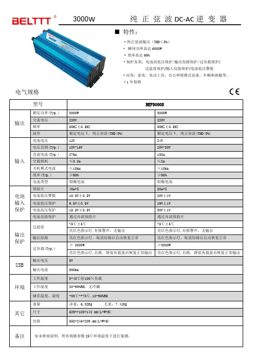
3000W 纯正弦波DC-AC逆变器■特性:●纯正弦波输出(THD<3%)●瞬间功率高达6000W●效率高达90%●保护各类:电池高低压保护/输出短路保护/过负载保护/过温度保护/输入反接保护/电池低压警报●应用:家电,电动工具,办公和便携式设备,车辆和游艇等。
●1年保修电气规格型号BEP3000S输出额定功率(Typ.) 3000W 3000W交流电压220V 220V频率50HZ±0.5HZ50HZ±0.5HZ波形额定电压下, 纯正弦波(THD<3%) 额定电压下, 纯正弦波(THD<3%)输入电池电压12V 24V电压范围(Typ.) 10V-15V 20V-30V 直流电流(Typ.) 276A 138A空载损耗≤3.8A ≤2A关机模式电流≤10mA ≤10mA 效率(Typ.) ≥90% ≥90% 电池类型铅酸电池铅酸电池电池输入保护保险片40A*8 20A*8电池低压警报10.5V±0.5V20V±1V电池低压保护9.5V±0.5V19V±1V电池高压保护15.5V±0.5V30V±1V电池反接保护通过内部保险片通过内部保险片输出保护过温度75℃±5℃75℃±5℃亮红色指示灯,有报警声,无输出亮红色指示灯,有报警声,无输出输出短路亮红色指示灯,取消短路后自动恢复正常亮红色指示灯,取消短路后自动恢复正常过负载(Typ.)≥ 3000W ≥3000W亮红色指示灯,自锁, 降低负载重启恢复正常输出亮红色指示灯,自锁, 降低负载重启恢复正常输出USB 输出电压5V输出电流500mA环境工作温度0-40℃@100%负载工作湿度20-90%RH,无冷藏储存温度、湿度-30℃-+70℃,10-95%RH其它重量净重:6.02Kg 毛重:7.41Kg 尺寸529**180*142 mm(L*W*H)包装558*246*209 mm(L*W*H)备注如未特别说明,所有规格参数25℃环境温度下进行量测。
IGBT驱动板TX-DA962A系列产品手册 说明书
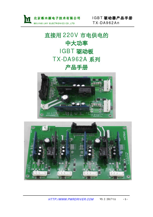
直接用220V市电供电的中大功率IGBT驱动板TX-DA962A系列产品手册目录一、概述 (4)二、结构框图 (4)三、电气参数 (4)3.1 极限参数 (4)3.2 驱动特性 (4)3.3 工作条件 (5)3.4 短路保护性能 (5)3.5 对输入电源要求 (5)四、输出波形 (6)4.1 软关断曲线 (6)4.2 说明 (6)五、尺寸结构 (6)5.1 外形尺寸示意图 (6)5.2 一单元主要元器件位置示意图 (7)5.3 接插件引脚说明 (7)5.3.1 输入电源插座Jp (7)5.3.2 输入信号插座Js (7)5.3.3 驱动输出插座Jo (7)六、应用电路说明 (7)6.1 驱动电源 (7)6.2 驱动板低压信号侧 (8)6.2.1 使能信号ENA (8)6.2.2 输入信号Vs (8)6.2.3 输出报警信号 (8)6.3 驱动器高压侧输出的连接 (8)6.3.1 驱动输出功率的计算 (8)6.3.2 IGBT的连接 (9)6.3.3 栅极电阻 (9)6.3.4 驱动2只并联的IGBT (9)6.4 保护参数的设置 (9)6.4.1 保护阈值设定Vn (9)6.4.2 盲区时间设定Tblind (9)6.4.3 软关断时间设定Tsoft (9)6.4.4 故障后再启动时间设定Trst (10)6.5 驱动输出波形的测试方法 (10)6.6 加装死区模块的说明 (10)七、相关产品信息 (10)7.1 TX-PA202 AC-DC模块电源 (10)7.2 TX-QP102(死区控制芯片) (11)7.3 TX-DA102D系列大功率 IGBT驱动板 (11)八、常见问题 (11)九、其它说明: (11)TX-DA962An 系列IGBT 驱动板一、概述• 自带AC/DC 辅助电源,直接从交流市电获取能量,有利于提高用户电源系统的效率。
• 也可用135-350V 的直流电源供电。
• DA962A 2、4为2、4单元驱动板,每路输出6A 电流,可驱动300A/1700V 以下的IGBT 。
- 1、下载文档前请自行甄别文档内容的完整性,平台不提供额外的编辑、内容补充、找答案等附加服务。
- 2、"仅部分预览"的文档,不可在线预览部分如存在完整性等问题,可反馈申请退款(可完整预览的文档不适用该条件!)。
- 3、如文档侵犯您的权益,请联系客服反馈,我们会尽快为您处理(人工客服工作时间:9:00-18:30)。
3.2.2
板上P8、P9接口为交流输出接口。高频模式时,经板上(L3、C13)LC滤波后直接提供220V纯正弦波输出。工频模式时,板上LC滤波电路(L1、C13)可以省去,滤波电感L1用粗铜丝短路,滤波电容C13不焊,输出SPWM波形,经外挂工频变压器和滤波电容后输出220V正弦波。可参考章节“4.3工频模式”。
驱动电源提供:需在板上的驱动电源接口(P5)另接一组+12V的驱动电源单独为驱动电路供电。
功率电源总线上的峰值电流约为:
ITOP= 1.414 * W / VAC= 1.414 * 1000VA / 220V≈6.5 A
板上的保险丝可选择10A - 20A的保险丝。
采样电阻:
RS= VSH/ ITOP= 0.5V / 6.5A≈0.08Ω
工频模式时,驱动电源接口(P5)可以不接,使用功率电源经板上降压电路降压后为驱动电路供电,根据输入的功率电源电压不同,配置跳线;若不使用板上降压电路,也可在驱动电源接口(P5)外接+12V的电源为驱动电路供电。具体配置见表3-1.
工作
模式
驱动电
源模式
风扇电
源模式
功率电源
(P3、P4)
驱动电源接口(P5)
EGP1000W逆变器功率板上由一个EGS001正弦波逆变器驱动板的专用接口、8个功率管两两并联组成的全桥功率单元、LC滤波单元、低压电源管理单元、电压电流反馈单元及温度检测单元。板上可安装散热片和风扇,并可通过EGS001上的风扇控制功能根据温度打开或关闭散热风扇。
2.
EG
图2-1. EGP1000W逆变器功率板电路原理图
高频模式时,板上已集成完整的电压反馈电路,能够自动实现稳压功能,且输出的交流电压可以通过调压电位器(R5)调节。工频电压反馈接口(P6、P7)不接,且用于工频电压反馈的整流桥芯片(U3可以省去,反馈电路上的4.7uF的电容不接。电压反馈部分原理图如图4-1所示:
图4-1高频模式反馈电路原理图
4.3
工频模式时,功率电源接口(P3、P4)只需输入低压直流电源即可,功率电源可由电池组或其他低压电源提供。同样,EGP1000W逆变器功率板输出的交流电压有效值和功率电源输入的直流电压关系仍需遵循:
3.2.3
板上P6、P7接口为工频电压反馈接口,仅在工频模式时使用。具体使用方法请参考章节“4.3工频模式”中的反馈说明。
3.3
EGP1000W逆变器功率板上有三个电源配置跳线:JP1、JP2、JP3。用以配置驱动电源及风扇电源。
高频模式时,需在驱动电源接口(P5)外接+12V的电源为驱动电路供电,风扇电源(P1)也需外接,且高频模式时JP2、JP3必须断开!
VAC< VDC/1.414
此时,板上的交流输出接口(P8、P9)需要接工频变压器的低压线圈输入端口,变压器高压线圈输出端口并一个2.2uF的CBB滤波电容。使用工频变压器时,板上的LC滤波器件(L1、C13)可以省去,滤波电感(L1)用粗铜丝短路,滤波电容(C13)不焊。输出及反馈电路如同4-2所示。
驱动电源(P5)主要为SPWM控制电路和功率管驱动电路供电,输入电压为+12V。工作在高频模式时,由于功率电源电压通常在330V以上,所以必须使用另外一组+12V的直流电源单独为驱动电路供电。工作在工频模式时,功率电源电压通常不大于60V,可使用功率电源通过板上降压电路为驱动电路供电,也可外接一组+12V的直流电源单独为驱动电路供电。
5.
EGP1000W
.
图4-1. EGP1000W逆变器功率板规格尺寸
风扇电源接口(P1)
降压器件U1
跳线
JP1
跳线
JP2
跳线
JP3
高频
模式
从P5口输入
从P1口输入
330V-450V
接+12V
外接
不焊
断开
断开
断开
工频
模式
从P5口输入
从P1口输入
12V-75V
接+12V
外接
不焊
断开
断开
断开
板上
降压
从
P1口
输入
12V-15V
不接
外接
不焊
断开
断开
短接
15V-25V
不接
外接
L7812
EGP1000W逆变器功率板用户手册
版本更新:V1.0:正式发行初版 (2011-05-04)。
1.
EGP1000W逆变器功率板是一款配套EG8010SPWM芯片和EGS001正弦波逆变器驱动板的专用功率底板,适用于3KVA以下的逆变单元。EGP1000W逆变器功率板具有两种工作模式:前级经高频变压器DC-DC升压后输入高压直流电至板上功率电源接口直接逆变输出模式(高频模式);直接输入低压直流电至板上功率电源接口逆变输出低压交流后经工频变压器升压输出高压交流(工频模式)。用户可根据需求选择工作模式及功率器件,并通过调压电位器调节交流输出电压。
4.
4.1
EGP1000W逆变器功率板共有两种工作模式:前级经高频变压器DC-DC升压后输入高压直流电至板上功率电源接口直接逆变输出模式(高频模式);直接输入低压直流电至板上功率电源接口逆变输出低压交流后经工频变压器升压输出高压交流(工频模式)。两种工作模式所用功率器件不同,用户可根据系统需求选型。工作在高频模式时,直流电压高,相同功率下电流小;工频模式时,直流电压低,相同功率下电流大。
若系统不需要隔离,则直接将工频变压器输出端口接到板上的工频反馈输入端,经过板上整流桥整流后由分压电阻分压到EGS001驱动板的VFB。另外工频反馈需要在EGS001的VFB脚与地之间加一个16V/4.7uF的电解电容(C12),工频模式电压反馈电路如图4-2所示。
图4-2工频模式反馈电路原理图(不隔离)
4.2
高频模式时,功率电源接口(P3、P4)需输入高压直流电源,功率电源电压需大于逆变单元交流输出的峰值,如需要有效值220V交流输出时,功率电源电压至少要大于311V。即:
VDC>VAC*1.414
一般需要在重载下稳定运行时,需要留有一定的余量,在220V交流输出时,建议功率电源电压为330V-450V。另外,高频模式下需在驱动电源接口(P5)上外接一组+12V的驱动电源,供驱动电路使用。
3.
3.1
图3-1. EGP1000W逆变器功率板
3.2
3.2.1
EGP1000W逆变器功率板共有三个电源接口:功率电源接口(P3、P4)、驱动电源接口(P5)及风扇电源接口(P1)。
图3-2. EGP1000W逆变器功率底板电源管理部分原理图
功率电源(P3、P4)主要为逆变全桥供电,为逆变输出提供电能。工作在高频模式时,功率电源为一组高压直流电源,若要逆变输出交流220V,则输入的直流功率电压须在330V ~ 450V之间,高压直流电源可采用高频变压器DC-DC升压得到。工作在工频模式时,功率电源为一组低压直流电源,通常电压不大于60V,可采用电池组或其他直流电源供电。
工频变压器低压线圈输入电压:
VACL(max) = VDC/ 1.414 = 48V / 1.414≈34 V
n (min) = VACH/ VACL(max)= 220 V / 34V = 6.5
即工频变压器低压线圈输入的交流电压有效值将小于34V,也就是说高压线圈与低压线圈的匝数比必须大于6.5。重载时建议留一定的余量,匝数比不宜太小。此时可以选用24V - 220V或30V - 220V的工频变压器。
采样电阻可使用功率电阻,如使用0.2Ω/2W的功率电阻,则使用3-4根功率电阻并联。
应用举例2:
48V DC -- 220V AC,使用工频模式加工频变压器逆变输出220V交流。
驱动电源提供:板上的驱动电源接口(P5)可以不接,驱动电源使用EG1181降压型开关电源模块,输入电压(+25V ~ +70V)、输出+12V/100mA。
当选择24V - 220V的工频变压器时,功率电源总线上的峰值电流约为:
ITOP= 1.414 * W / VACL= 1.414 * 1000VA / 24V≈60A
板上的保险丝可选择(80A-100A)的保险丝。
采样电阻:
RS= VSH/ ITOP= 0.5V / 60A≈0.008Ω
采样电阻须使用康铜丝,如使用20mΩ的康铜丝,则使用3-4条康铜丝并联。
断开
短接
断开
25V-75V
不接
外接
EG1181
断开
短接
断开
共用
功率
电源
12V-15V
不接
不接
不焊
短接
短接
短接
15V-25V
不接
不接
L7812
短接
短接
断开
25V-75V不接不接EG181短接短接
断开
表3-1工作模式与电源配置表格
板上功率电源总线上有三个滤波电解电容(C1、C2、C3)及两个去耦电容(C14、C15)。电容的耐压值需根据功率电源电压选择。如工作在高频模式,功率电源总线电压为(330V~400V),则选择耐压为450V。若工作在工频模式,功率电源总线电压为48V,则选择电容耐压应为63V。电解电容容量根据实际系统功率选择,一般高频模式应大于47uF,工频模式应大于470uF。去耦电容一般选择0.1uF的CBB电容,耐压必须大于功率电源总线电压。若电容耐压小于功率电源总线电压,则可能造成电容爆炸危险!
输入的功率电源电压VDC需大于交流输出峰值312V,建议留有余量,特别是重载时,功率电源电压要高于交流输出峰值电压,电压范围应在330V ~ 450V。功率电源电源电压也不宜过高,过高将导致MOSFET选型困难,并且会增加高压电源滤波电容成本。330V ~ 450V的功率电源可使用高频变压器DC-DC升压得到。