SG001 正弦波逆变器驱动板用户手册
逆变器用户使用手册
资料范本本资料为word版本,可以直接编辑和打印,感谢您的下载逆变器用户使用手册地点:__________________时间:__________________说明:本资料适用于约定双方经过谈判,协商而共同承认,共同遵守的责任与义务,仅供参考,文档可直接下载或修改,不需要的部分可直接删除,使用时请详细阅读内容GDLYEC-PV-3~270/500光伏并网逆变器用户使用手册版本2.0国电龙源电气有限公司目录TOC \o "1-3" \h \z \u HYPERLINK \l "_Toc327278738" 1关于本手册 PAGEREF _Toc327278738 \h 3HYPERLINK \l "_Toc327278739" 1.1 前言 PAGEREF_Toc327278739 \h 4HYPERLINK \l "_Toc327278740" 1.2 内容简介 PAGEREF_Toc327278740 \h 4HYPERLINK \l "_Toc327278741" 1.3 面向读者 PAGEREF_Toc327278741 \h 4HYPERLINK \l "_Toc327278742" 1.4 手册使用 PAGEREF_Toc327278742 \h 4HYPERLINK \l "_Toc327278743" 2 安全须知 PAGEREF_Toc327278743 \h 5HYPERLINK \l "_Toc327278744" 2.1 警示符号说明 PAGEREF_Toc327278744 \h 6HYPERLINK \l "_Toc327278745" 2.2 安全提示 PAGEREF_Toc327278745 \h 7HYPERLINK \l "_Toc327278746" 2.3 操作中的注意事项 PAGEREF _Toc327278746 \h 9HYPERLINK \l "_Toc327278747" 3 产品简介 PAGEREF_Toc327278747 \h 10HYPERLINK \l "_Toc327278748" 3.1 光伏并网系统 PAGEREF_Toc327278748 \h 11HYPERLINK \l "_Toc327278749" 3.2 产品特点 PAGEREF_Toc327278749 \h 11HYPERLINK \l "_Toc327278750" 3.3 电气原理 PAGEREF_Toc327278750 \h 12HYPERLINK \l "_Toc327278751" 3.4 产品外观 PAGEREF_Toc327278751 \h 14HYPERLINK \l "_Toc327278752" 4 产品功能与LCD操作指南PAGEREF _Toc327278752 \h 17HYPERLINK \l "_Toc327278753" 4.1 GDLYEC-PV-3~270/500主要功能 PAGEREF _Toc327278753 \h 18HYPERLINK \l "_Toc327278754" 4.1.1 并网发电 PAGEREF_Toc327278754 \h 18HYPERLINK \l "_Toc327278755" 4.1.2 MPPT功能 PAGEREF_Toc327278755 \h 18HYPERLINK \l "_Toc327278756" 4.1.3低电压穿越功能 PAGEREF _Toc327278756 \h 18HYPERLINK \l "_Toc327278757" 4.1.4 保护功能 PAGEREF_Toc327278757 \h 19HYPERLINK \l "_Toc327278758" 4.1.5 远程控制功能 PAGEREF _Toc327278758 \h 20HYPERLINK \l "_Toc327278759" 4.1.6自动开关机功能 PAGEREF _Toc327278759 \h 20HYPERLINK \l "_Toc327278760" 4.2 GDLYEC-PV-3~270/500运行模式 PAGEREF _Toc327278760 \h 20HYPERLINK \l "_Toc327278761" 4.3 GDLYEC-PV-3~270/500 LCD操作指南 PAGEREF _Toc327278761 \h 22HYPERLINK \l "_Toc327278762" 4.3.1 LCD主界面 PAGEREF_Toc327278762 \h 22HYPERLINK \l "_Toc327278763" 4.3.2 LCD控制指令发送 PAGEREF _Toc327278763 \h 24HYPERLINK \l "_Toc327278764" 5 产品安装 PAGEREF_Toc327278764 \h 30HYPERLINK \l "_Toc327278765" 5.1 注意事项 PAGEREF_Toc327278765 \h 31HYPERLINK \l "_Toc327278766" 5.2 机械尺寸 PAGEREF_Toc327278766 \h 31HYPERLINK \l "_Toc327278767" 5.3 放置与移动 PAGEREF_Toc327278767 \h 31HYPERLINK \l "_Toc327278768" 5.4 直流输入线缆连接 PAGEREF _Toc327278768 \h 32HYPERLINK \l "_Toc327278769" 5.4.1 直流输入电气参数规格PAGEREF _Toc327278769 \h 32HYPERLINK \l "_Toc327278770" 5.4.2 直流输入线缆要求 PAGEREF _Toc327278770 \h 33HYPERLINK \l "_Toc327278771" 5.4.3 线缆连接 PAGEREF_Toc327278771 \h 33HYPERLINK \l "_Toc327278772" 5.5 交流输出线缆连接 PAGEREF _Toc327278772 \h 36HYPERLINK \l "_Toc327278773" 5.5.1 交流输出电气规格 PAGEREF _Toc327278773 \h 36HYPERLINK \l "_Toc327278774" 5.5.2 交流输出线缆要求 PAGEREF _Toc327278774 \h 36HYPERLINK \l "_Toc327278775" 5.5.3 线缆连接 PAGEREF_Toc327278775 \h 36HYPERLINK \l "_Toc327278776" 5.6 系统地线连接 PAGEREF_Toc327278776 \h 38HYPERLINK \l "_Toc327278777" 5.6.1 地线线缆要求 PAGEREF _Toc327278777 \h 38HYPERLINK \l "_Toc327278778" 5.7 远程监控通信线连接 PAGEREF _Toc327278778 \h 38HYPERLINK \l "_Toc327278779" 6 产品运行指南 PAGEREF _Toc327278779 \h 40HYPERLINK \l "_Toc327278780" 6.1 启动 PAGEREF_Toc327278780 \h 41HYPERLINK \l "_Toc327278781" 6.2 关机 PAGEREF_Toc327278781 \h 42HYPERLINK \l "_Toc327278782" 7 电气特性 PAGEREF_Toc327278782 \h 431关于本手册关于本章本章介绍了本手册的主要内容、面向的读者、手册使用须知以及手册所使用的符号定义,帮助用户更好的阅读本手册内容。
IPower-Plus系列高频纯正波逆变器用户手册说明书
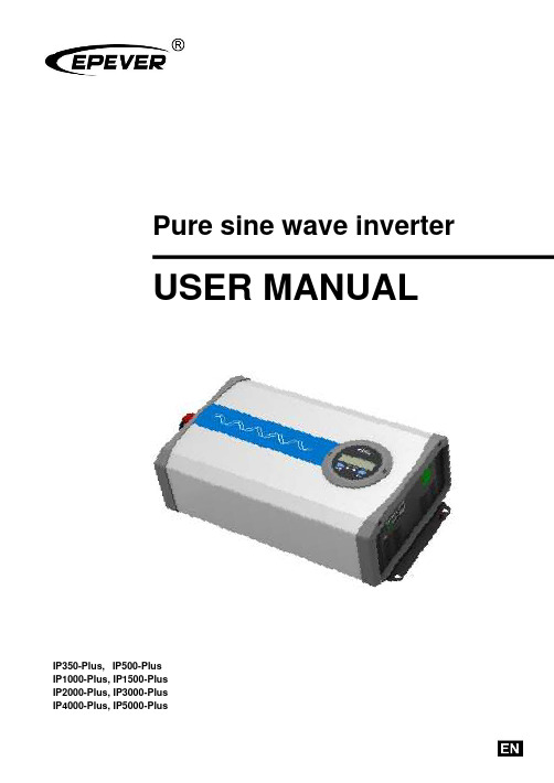
Pure sine wave inverterUSER MANUALIP350-Plus,IP500-PlusIP1000-Plus, IP1500-PlusIP2000-Plus, IP3000-PlusIP4000-Plus, IP5000-PlusContentsImportant safety instructions 11 Overview 52 Appearance 73 Naming rule 114 Connection diagram 135 Remote meter 155.1 Appearance 155.2 Buttons 155.3 LCD interface 165.3.1 Real-time interface 165.3.2 Parameters setting 165.3.3 Power Saving Mode 165.3.4 Parameters user define 185.4 Error code 196 Installation 206.1 Attentions 206.2 Wire size and circuit breaker 206.3 Mounting 236.4 Rotate the LCD 287 Protections 298 Troubleshooting 339 Maintenance 3410 Specifications 35 Appendix 1 Disclaimers 44Important safety instructionsPlease reserve this manual for future review.This manual contains all safety, installation, and operation instructions for the IPower-Plus series high-frequency pure sine wave inverter ("inverter" referred to in this manual).1. Explanation of symbolsPlease read related literature accompanying the following symbols to efficiently use the product and ensure personal and property safety.The entire system should be installed by professional and technical personnel.2. Requirements for professional and technical personnel•Professionally trained;•Familiar with related safety specifications for the electrical system;•Read this manual carefully and master related safety cautions.3. Professional and technical personnel is allowed to do•Install the inverter to a specified location.•Conduct trial operations for the inverter.•Operate and maintain the inverter.4. Safety cautions before installation5. Safety cautions for mechanical installation6. Safety cautions for electrical connection7. Safety cautions for controller operation8. Dangerous operations which would cause electric arc, fire or explosion•Touch the wire end that hasn't been insulation treated and maybe electriferous.•Touch the wiring copper row, terminals, or internal modules of the inverter that may be electriferous. •The connection of the power cable is loose.•Screw or other spare parts inadvertently falls into the inverter.•Improper operations by untrained non-professional or technical personnel.9. Safety cautions for stopping the inverter•After the inverter stop running for five minutes, the internal conductive modules could be touched. •The inverter is allowed to restart after removing the faults, which affects safety performance. •There are no serviceable parts inside. If any maintenance service is required, please contact our service personnel.10. Safety cautions for inverter maintenance•It is recommended to check the inverter with testing equipment to ensure there is no voltage and current.•When conducting electrical connection and maintenance, post a temporary warning sign or put up barriers to prevent unrelated personnel from entering the electrical connection or maintenance area. •An improper operation of the inverter may cause personal injury or equipment damage.•Please wear an anti-static wrist strap to prevent static damage or avoid unnecessary contact with the circuit board.1 OverviewIPower-Plus is a new generation of pure sine wave inverter compatible with the lithium battery system. This new inverter adopts surge current suppression technology to effectively prevent the surge current from damaging the lithium battery cells and BMS (Battery Management System). Also, adopting the voltage and current double closed-loop control algorithm brings the inverter a faster response and better resistance to the load impact. The inverter selects key components with a high power density and long lifespan to provide a stable and reliable power guarantee. The optional communication solutions allow users to monitor the real-time status or change the parameters wherever.The inverter can be widely used in DC to AC areas, such as solar AC power system, vehicle system, RV power supply, security monitoring system, emergency lighting system, field power system, household power system, etc. With an excellent EMC (Electro Magnetic Compatibility) characteristic, the inverter is also suitable for occasions with high power quality requirements.Features:•Completely electrically isolated design for input and output•Full digital double closed-loop control•Excellent EMC characteristic, widely applied to higher quality power system•Advanced SPWM technology and pure sine wave output.•Input surge current suppression technology, applying to the lithium battery system•Outstanding load resistance to impact, applying to the air conditioners, washing machines, refrigerators, etc.•High power density and high-quality components to ensure the reliability•Output power factor up to 1•Low loss of zero loads and standby. Low THD (Total Harmonic Distortion). High conversion efficiency•Extensive protections: input reverse polarity/under voltage/over voltage, output overload/short circuit/overheating•Air cooling is controlled by temperature and load•Rotatable LCD meter to simplify the system wiring①•Friendly LCD meter to simply monitor and parameter configure①•Remote control by the phone Apps and PC software •Configurable output voltage, output frequency and baud rate②•Enable power saving mode(PSE) conveniently②•Charging mobile phones, DC fans, and other electrical equipment by the USB port•Support a variety of options by connecting with the RS485 com. port④•External switch contact design to allow remote control•EN/IEC62109, EN61000-6-1/3, RoHS, ETL and FCC approved①There is no LCD meter for the IP350-Plus series.②Configure the parameters via the local LCD meter (no including the IP350-Plus series),remote LCD meter, phone Apps, or PC software.③This function is unavailable for inverters with 48V input voltage.④There is no communication isolation design for inverters with 12V/24 input voltage. Thisfunction(communication isolation design) is just for inverters with 48V input voltage.2 Appearance∙IP350-xx-Plus✓Appearance with decorative cover is suitable for AC output of T-terminal / C-Chinese dual socket / N-North America✓Appearance without decorative cover is suitable for AC output of A-Australia / E-European / F-French / UK-United Kingdom∙IP500-xx-Plus✓Appearance with decorative cover is suitable for AC output of T-terminal / C-Chinese dual socket / N-North AmericaAppearance without decorative cover is suitable for AC output of A-Australia / E-European / F-French / UK-United Kingdom∙IP1000-xx-Plus∙IP1500-xx/IP2000-2x/IP2000-4x/IP3000-42-Plus∙IP2000-1x-Plus∙IP3000-1x-Plus∙IP3000-2x-Plus∙IP3000-41/IP4000-4x/IP5000-4x-Plus①Cooling fan∙Conditions to start the cooling fan:∙Conditions to stop the cooling fan:② The AC output port varies with different products. Please refer to chapter 3 Naming rule for thespecific supported types.③USB output port is not available for inverters with 48V input voltage.3 Naming ruleExplanations for the AC output port:★ GFCI outlets need to be tested after power-on to ensure proper operation.PreparationConnect a circuit breaker and an AC load (it is recommended to use a night light to observe the status conveniently) to the GFCI outlet. Turn on the inverter after confirming the wiring.Testing1) If the red LED is ON solid, it indicates that the GFCI outlet is damaged; please replace a new one. 2) If the LED is green ON after it flashes in red three times, connect the circuit breaker, and the night light will be turned on. Then, press the "TEST" button to observe the testing status:① The "TEST" button always pops up, and the night light keeps ON solid. It indicates that the GFCIwiring is an error; please correct the wrong wiring.② The "TEST" button goes down, while the "RESET" button pops up. The LED and the night light areturned off, indicating the GFCI outlet is normal (Note: Press the "RESET" button again to recover the load output).4 Connection diagramIP350-xx-Plus (take the “Appearance with decorative cover” as an example)IP500-xx-Plus(take the “Appearance with decorative cover” as an example)IP1000-xx/IP1500-xx/IP2000-2x/IP2000-4x/IP3000-42-PlusIP2000-1x-PlusIP3000-1x-PlusIP3000-2x/IP3000-41/IP4000-4x/IP5000-4x-Plus5 Remote meter5.1 AppearanceThe LCD display can be viewed clearly when the angle between the end-user's horizontal sight and the LCD screen is within 90°. If the angle exceeds 90°, the LCD display cannot be viewed clearly.5.2 Buttons+5.3 LCD interface5.3.1 Real-time interfaceClick orto browse the real-time interface.5.3.2 Parameters settingOperation:Step1: In the real-time interface, pressfor 2s to enter the parameter setting interface.Step2: Click or to select the parameter to be configured.Step3: Press for 2s to enter the configuration interface of the specified parameter.Step4: Click or to configure the parameter value.Step5: Press for 2s to confirm the configuration.Step6: Click + to exit the current interface.5.3.3 Power Saving ModeUsers can enable the power saving mode and set the PSI/PSO value by the/button (TheBattery voltage Load voltage Load currentLoad frequencyLoad powerminimum power step is 1VA).When the actual load power is lower than the PSI (the power to enter the power saving mode), the system will automatically switch to the power saving mode, and then the device output is turned on for 1s and turned off for 5s.When the actual load power exceeds the PSO (the power to exit the power saving mode), the inverter will automatically exit the power saving mode and resume work.1) Enable power saving mode (PSE)Step1: In the real-time interface of the remote meter, press and hold the button to enter the parameters setting interface.Step2: Click the or button to select the PSE parameter.Step3: Press and hold the button until the PSE parameter (OFF default) flashes.Step4: Click the or button to set the PSE status.•Select ON to enable the power saving mode.•Select OFF to disable the power saving mode.Step5: Press and hold the button to confirm.2)Set the power to exit the power saving mode (PSO)Step1: In the parameters setting interface, click the or button to select the PSO parameter.Step2: Press and hold the button until the PSO value flashes.Step3: Click the or button to set the PSO parameter.•Click the button to decrease the PSO value by 1.•Click the button to increase the PSO value by 1.•Press and hold the button to increase the PSO value by 10. After ten adding, the PSOvalue will increase by 100 each time. When the button is released, press and hold itagain to repeat the above operation (Note: The setting parameter cannot exceeds the userdefine, or it will back to the initial value to start the loop).Step4: Press and hold the button to confirm.3)Set the power to enter the power saving mode (PSI)Step1: In the parameters setting interface, click the orbutton to select the PSI parameter.Step2: Press and hold the button until the PSI value flashes. Step3: Click theorbutton to set the PSI parameter.• Click the button to decrease the PSI value by 1. • Click thebutton to increase the PSI value by 1.• Press and hold thebutton to increase the PSI value by 10. After ten adding, the PSIvalue will increase by 100 each time. When thebutton is released, press and hold itagain to repeat the above operation (Note: The setting parameter cannot exceeds the user define, or it will back to the initial value to start the loop).Step4: Press and hold thebutton to confirm.5.3.4 Parameters user define① After configuring the parameters marked with ①, the inverter will restart automatically. It willresume work according to the new parameter value.② Due to the length limit of the LCD displayed data, when the baud rate is set to 115200, the valuedisplayed on the LCD is 1152.③ For the parameter user defines, please refer to the input voltage rules in chapter 7 Protections.Otherwise, the parameter setting will not succeed.5.4 Error code6 Installation6.1 Attentions∙Read all the installation instructions carefully in the manual before installation.∙Be very careful when installing the batteries. When installing the open-type lead-acid battery, please wear eye protection and rinse with clean water in time for battery acid contact.∙Keep the battery away from any metal objects, which may cause a short circuit of the battery.∙Loose power connections and corroded wires may result in high heat that can melt wire insulation, burn surrounding materials, or even cause a fire. Ensure tight connections and secure cables with clamps to prevent them from swaying while moving the inverter.∙The DC input voltage must strictly be following the parameter table. Too high or too low DC input voltage will affect the inverter's normal operation and damage it. The surge voltage shall be less than 20V@12V system, less than 40V@24V system, and less than 80V@48V.∙Select the connection cables according to the current density of 3.5A/mm2 or less.∙Avoid direct sunlight and rain infiltration when installing it outdoor.∙After turn off the power switch, do not open or touch the internal component immediately. Related operations are performed after 10 minutes.∙Do not install the inverter in a harsh environment such as humid, salt spray, corrosion, greasy, flammable, explosive, or dust accumulation.∙The AC output is of high voltage, do not touch the wiring connection to avoid electric shock.∙To prevent injury, do not touch the fan while it is working.6.2 Wire size and circuit breakerThe wiring and installation methods must conform to the national and local electrical code requirements. Wire, terminals, and circuit breaker selection for battery★ According to the recommended battery wire size, 2 battery wires, connected in parallel, are necessary for IP1500-11-Plus, IP1500-12-Plus, IP2000-11-Plus, IP2000-12-Plus, IP3000-21-Plus, IP3000-22-Plus, and IP5000-42-Plus. 4battery wires, connected in parallel, are necessary forWire and circuit breaker selection for AC output6.3 MountingInstallation procedures:Step1: Professional personnel reads this manual carefully.Step 2: Determine the installation location and heat-dissipation spaceTo ensure natural thermal convection, you should install the inverter in a place with sufficient airflow and a minimum clearance of 150mm from the inverter's upper and lower edges.IP350-xx-Plus (take the “Appearance with decorative cover” as an example)IP500-xx-Plus (take the “Appearance with decorative cover” as an example)IP1000-xx/IP1500-xx/IP2000-2x/IP2000-4x/IP3000-42-PlusIP2000-1x-PlusIP3000-1x-PlusIP3000-2x/IP3000-41/IP4000-4x/IP5000-4x-PlusStep3: WiringWiring sequence (The following wiring sequence is illustrated in the appearance "IP2000-2x-Plus",wiring positions of other inverters. Please refer to chapter 2 Appearancefor reference.) 1. Ground connectionThe wire size for the ground connection must be thicker or equal to that for the AC output. Refer to chapter 6.2 Wire size and circuit breaker for detailed wire size.2. Battery connection3. AC loads connection1) Definition of the AC output portIt varies with different product models; please refer to the actual product. The following takes the AC terminal as an example.✦It is recommended to use a multi-stranded wire with a wire diameter of not more than 6mm2.✦Add solder to the connection point when selecting the multi-stranded wire and directly insert it into the corresponding port.✦Stop the inverter before removing the wiring. Then, insert a sharp tool into the small hole (on the top of the port) and pull out the wiring forcefully.2) Connect the AC load4. Optional accessories connection1) RS485 communication portRJ45 Pin Definition:2) Connect optional accessories5. USB port connection (USB port is not available for inverters with 48V input voltage.)Step 4:Power on the inverter⑴Connect the breaker at the inverter input terminal or the fuse at the battery end.⑵Turn on the inverter switch; the power indicator will be lighted on, indicating a normal AC output.⑶Turn on the AC loads one by one and check the inverter's running status and the loads.⑷If the fault indicator flashes red and the buzzer alarms after powering the inverter, pleaseimmediately turn off the load and the inverter. Clear the faults according to chapter 8 Troubleshooting.6.4 Rotate the LCD⑴Remove the screws of the LCD unit with a screwdriver, and rotate it 180°.⑵Secure the screws of the LCD unit to the inverter.7 Protections1) Input reverse polarity protectionWhen the DC input terminal's polarity is reversed, the indicator will not light up after power on. The buzzer will not sound, and the inverter will not work. The inverter will start to work normally after correcting the error wiring.2) Input voltage protection•The following rules must be followed when modifying the battery's input voltage parameters:A. Over voltage limiting voltage (16.2/32.2/64.4V) ≥Over voltage disconnect voltage ≥Overvoltage reconnect voltage +1V.B. Over voltage reconnect voltage ≥ Low voltage reconnect voltage.C. Low voltage reconnect voltage ≥ Low voltage disconnect voltage +1V.D. Low voltage disconnect voltage ≥ Low voltage limiting voltage (10.5/21/42V).•Detail status is shown as the following when the input voltage protection occurs.Buzzer beeps.3) Overload protectionThe red indicator slowly flashes..The red indicator slowly flashes..The red indicator slowly flashes.The red indicator slowly flashes.★ When the overload protection happens on IP2000-11-Plus, IP3000-21-Plus or IP3000-22-Plus, the AC output is shut down directly and cannot be recovered automatically..The red indicator slowly flashes..The red indicator slowly flashes.. The red indicator slowly flashes.The red indicator slowly flashes..4) Output short circuit protection5) Inverter over temperature protection8 Troubleshooting9 MaintenanceThe following inspections and maintenance tasks are recommended at least two times per year for good performance.•Make sure no block on airflow around the inverter. Clear up any dirt and fragments on the heat sink. •Check all the naked wires to ensure insulation is not damaged by sun exposure, frictional wear, dryness, insects or rats, etc.•Verify the indicator display is consistent with the actual operation.•Confirm that terminals have no corrosion, insulation damage, high temperature, burnt/discolored sign, and tighten terminal screws to the suggested torque.•Clear up dirt, nesting insects, and corrosion in time.•Check and confirm that the lightning arrester is in good condition. Replace a new one in time to avoid damaging the inverter and other equipment.10 Specifications35①It is measured in the condition of continuous output power and rated input voltage.②It means the max. output efficiency when the inverter is connected with different loads under the rated input voltage.36①It is measured in the condition of continuous output power and rated input voltage.②It means the max. output efficiency when the inverter is connected with different loads under the rated input voltage.37①It is measured in the condition of continuous output power and rated input voltage.②It means the max. output efficiency when the inverter is connected with different loads under the rated input voltage.①It is measured in the condition of continuous output power and rated input voltage.②It means the max. output efficiency when the inverter is connected with different loads under the rated input voltage. 220/230/240VAC output①It is measured in the condition of continuous output power and rated input voltage.②It means the max. output efficiency when the inverter is connected with different loads under the rated input voltage.①It is measured in the condition of continuous output power and rated input voltage.②It means the max. output efficiency when the inverter is connected with different loads under the rated input voltage.①It is measured in the condition of continuous output power and rated input voltage.②It means the max. output efficiency when the inverter is connected with different loads under the rated input voltage.①It is measured in the condition of continuous output power and rated input voltage.②It means the max. output efficiency when the inverter is connected with different loads under the rated input voltage.Appendix 1 DisclaimersThe warranty does not apply to the following conditions:•Damage is caused by improper use or an inappropriate environment (humid, salt spray, corrosion, greasy, flammable, explosive, dust accumulative, or other severe environments).•The actual current/voltage/power exceeds the limit value of the inverter.•Damage caused by working temperature exceeds the rated range.•Arc, fire, explosion, and other accidents are caused by failure to follow the inverter stickers or manual instructions.•Disassemble and repair the inverter without authorization.•Damage caused by force majeure.•Damage occurred during transportation or handling.•Before using precise instruments, such as a medical instrument, end-users must read the manual carefully and ensure the inverter's output power/output voltage is suitable. We are not responsible for the instrument damage caused by improper use.HUIZHOU EPEVER TECHNOLOGY CO., LTD. Tel: +86-752-3889706E-mail:***************。
SG1K5TL光伏并网逆变器中文使用手册(说明书)

SG使用说明书1-en

Three-phase Dry-type TransformerOperator’s ManualI. Designation of the model numberSG—400KVA 380/1140VInput/output voltage ratio: 380/1140VRated kilovolt ampere:400KVAII. StructureThe transformer consists of a laminated winding iron core, which is made of the premium silicone sheet. The rated input of the transformer is 380V in three phases with the rated output 1140V, with the mode of connection being △/Y O.N is the central line in the way of connection Y O.III. Environmental requirements for the application of the product3.1A m b ie n t t e mp e ra t u re:+40℃(u p p e r l im it) t o-5℃(lo we r l im it)(i n d o o rs);3.2 A l t i t u d e:n o t t o b e m o re t h a n1000m;3.3Re la t i ve h u m id it y:d a i l y a ve ra ge≤95%a n d m o n t h l y a ve ra g e≤90%;3.4E a rt h q u a k e in t e n s it y ≤8d e g re e s;3.5I n a p la ce wit h n e i t h e r ri sk o f f ir e o r e xp lo s io n n o r st ro n g vi b r a t io n.3.6W it h n o d e t r im e n t a l f u m e o r st e a m a n d n o se ri o u s m o ist u re o r wa t e rd r ip p in g;3.7 W it h o u t e xce s si ve co r ro s i ve d u st,st e a m o r s a l t y f o g;VI. Main technical parameters of the transformerF o r t h e d e ta il s,re f e r t o“Re p o rt o n t h e I n s p e ct io n o f t h e P ro d u c t”V. Examination of the transformer before putting into the use5.1A f t e r t h e lo n g d i sta n ce t ra n sp o rta t io n o f t h e t r a n sf o rm e r,e xa m in a t io n i s t o b e m a d e t o se e if t h e iso la t io n b e t we e n t h e i ro n co re a n d t h e c la m ps a n d yo ke b o l t i s in go o d o rd e r,a n y lo o se n ing o f th ef a st e n e r s,t h e d ista n ce o f is o la t io n b e t we e n t h e d iff e re n t pa rt s inc o m p l ia n ce wi t h t h e re q u i re m e n t s a nd a n y d a m a ge of t h e le a d s.5.2B e f o re t h e t ra n sf o rm e r is p u t in t o o p e ra t io n,it m u st b e ch e c ke d f ora l l t h e d a ta t ob e i n co m p l ia n ce wi t h t h e re qu i re m e n ts.VI. Operation of the transformer6.1 Preparatory works before the operation of the transformerB e f o re t h e t ra n sf or m e r i s p u t in t o o p e ra t io n,t h e pa ra m e t e r s sh o wn i n t h e n a m e p la t e s h o u ld b e ch e c ke d t o se e if t h e vo l ta ge in d ica t e d o n t h e n a m e p la t e i s in co m p l ia n ce wi t h t h e l in e vo lta g e.T h e g ro u n d in g d e vi ce o f t h e t ra n sf o rm e r is t o b e in sp e c t e d f o r b e in g in go o d o rd e r a n d i so la t io n o f t h e t ra n sf o rm e r f o r b e in g i n c o n f o rm i t y.T h e t ra n sf o rm e r is n o t t o b e p u t in t o o p e ra t io n u n t il e ve r yt h in g is in c o m p lia n ce wi t h t h e r e qu i re m e n ts.6.2Cr it e r ia f o r t h e o p e ra t io n①P e rm i ss ib le t e m p e ra t u re r is e:D u r in g t h e o p e r a t io n o f t h e t ra n sf o rm e r,it sh o u ld n o t e xce e d t h e t e m p e ra t u re(C l a s s F)p e rm it t e df o r t h e e le ct r ic in s u la t i ng m a t e r ia l u n d e r th e n o rm a l c o n d it io n s.②Pe rm issib le loa d: W hen t he t ran sf o rme r is u nd er loa d, it will be mo re hea ted if the lo ad is highe r wit h th e temp e rat u re rise be in g h igher d ue to the he at ing cau sed b y t he lo ss of cop pe r and iron. Thu s,it is re qu ired not to e xcee d th e ra ted va lu e spe cif ied in t he name plate du ring t he ope rat io n of t h e t ran sf orm e r.③Pe rm issib le va ria t ion of th e vo lta ge: Du rin g the o pe ra tion t he vo lta ge a pp lied to the t ra nsf o rme r ma y e qua l to o r less th an the nom ina l vo lta ge of the t ra nsf o rm e r. B ecau se of the supe r-sat u ra t ion afte r t he iron co re of the t ra nsf o rm er is ma gn et ize d, e ven if a lo we r o ve rrat in g vo ltage is app lie d t o th e t ran sf orm e r, it will cau se t he ma gn et ic indu ct ion to in crea se in a la rge ma gn it ude u ne ve nly, wh ich is espe cia lly dan ge rou s to t he t ransf o rme r wit h a h igh vo lta ge. The ref ore, t he volta ge ap plied to the t ran sf orm e r e xt e rn ally sha ll n o rma lly n ot e xceed t he ra ted va lue an d it isre qu ired th e se con da ry cu rren t of th e t ran sf orm e r n o t o b e mo re t han the ra ted va lue.④Pe rm issib le value of the d ie lect ric re sistan ce: No rma lly the me ga-me te r ra te d at1000-2500 vo lta ge is used to mea su re t he va lue of t he d ielect ric resista nce. The ba sic me tho d u sed to me asure t he iso lat ion con dit ion of the tra nsf o rme r is t o compa re t he value of the d ie lect ric re sistan ce mea su re d in the o pe ra t ion wit h the o riginal data det e rmined b ef ore t he o pe rat ion.In th e measu reme nt, un de r the co nd it ion of ide nt ica l e n viro nme nta l hum idit y, if th e value of t he d ie le ct ric re sistance re duced to 50% of t he in it ia l va lu e o r le ss, it is to b e d eemed as ina pp ro p ri ate.VII. Maintenance, examination and defective analysis of the transformer7.1 E xam ina t ion of t he t ran sf o rme r①Time of t he exa m ina t ion: Du t y pe rson ne l sho u ld be a va ilablef re qu ent ly in t he su b stat ion wit h t he t ran sf orm e r to be e xam in ed a t least o nce a da y.②Cont ent of t he exa m ina t ion:E xt e rna l e xam ina tion: It is t o be e xam ine d if the no ise ind ica t in g the a co ust ic n atu re of the t ran sf orm at io n is to o h igh an d an y ne w tone o ccu rred; if t he re is an y abn o rma lit y in t he cab le an d b us; if th e re is a ny t empe ratu re rise in th e t ran sf o rme r.7.2 Trou bleshoo t in g of the t ra nsf o rme r①Dete rio rat io n of t he iso la t ion:Du rin g the ope rat ion of the t ran sf orm e r, t he re will usua lly be the ph enome non of d ete rio rat io n of the iso lat ion.The mo st f undame nta l f eat u re of the de te rio ra t ion of the iso lat ion is t he d ecre ase of t he die le ct ric re sista nce, cau sin g t he in crea se of the lea ka ge cu rrent in th e o pe ra t ion an d se riou s he at in g an d in crea se of the tem pe ra tu re rise, lea d in g t o the f ur t he r a gin g of the iso lat ion.If it is to cont inue, t he re will be ve ry se riou s afterm ath. Onecau se f or t he de terio ra t ion of the iso la t ion is t he iso la t ion be in g we tt ed.A not he r ca use is th e iso lat ion be in g a ge d.②The temp e rat ure rise is to o h igh.The cau se s f o r th e tempe ratu reb ein g to o h igh a re:a Th e cu rren t is too la rge wit h t he loa d be in g t oo h igh, e xceed in g the lim it p e rmissib le f o r the t ran sf o rme r: Fo r the t ran sf o rme r wit h the mode of con nect ion be in g Y/Y0-12,it will be o ve r hea ted i f t he loa d is n ot in e qu ilib rium in t he t h ree p ha se s.The circu it of th e t ra nsf o rme r ma y be b roke n.If the circu it e xt e rna l to an y one p hase is b roke n in the △con nect ion, th e re will b e circu la t in g cu rren t th rou gh the in te rn al win din g, cau sin g t he lo ca l o ve rlo ad and loo se nin g of th e clamp in g scre w of the t ran sf orm e r (it is a def e ct ive u su ally o ccu rrin g due to the vib rat io n of the t ran sf orm e r).B Poo r ve nt ila t io n: d ust a ccumu la ted on the su rf ace of the t ran sf orm at io n wit h the a ir cha nne l b lo cked, rising of t he am b ient t empe ratu re, et c.C In te rn a l dama ges of t he t ra nsf o rme r, su ch a s the d ama ge of the co ila nd sh o rt circu it.③Abn o rma l sound s:Du rin g t he op e rat io n of the t ra nsf o rme r,the con t inuo us a nd un if o rm no ise will b e h ea rd, wit h the soun d f rom the d iff e ren t t ype s of t ran sf orm e r be in g d iff erent.The t ran sf o rme r is b igge r, t he so und la rge r. In some t ran sf o rmers, th e iron co re is not lam ina ted in a cro ss wa y bu t p ressed t ight ly wit h th e bo lts after lam in ate d nea t ly in to a b lo ck. Th us, the sou nd will be esp ec ia lly la rge d urin g th e op e rat ion. Ho we ve r,th e re is n o cha n ge in th is kind of soun ds each t ime wh en th e y a re hea rd.An d,it will no t aff ect th e no rma l op e ration.In ca se an y a bno rma l sou nd is f o und, e xam ina tion sh ou ld be m ad e acco rd in g t o the n atu re of the sou nd. If the so und b ecome s la rger in the o pe ra t ion, it is to e xam in e if the vo lta ge app lie d e xt e rna lly is too h ighe r an d if the iron core is t oo loo se. If it is too loo se,it must be clam ped t ight ly.If an y “squ ea k” n oise is hea rd f rom the t ra nsf o rme r,it ind ica ted th ere is f la sho ve r. It m ust b e e xam ine d t o see if th e sha rp se ct ion of th e metal pa rts in t he t ran sf o rm er t o b e a bat ed.If the re is an y “crackin g” n oise hea rd f rom the t ran sf o rme r, ind icat ing t he ph enome non of b rea k do wn, wh ich ma y o ccu r bet w ee n the co il o r iron co re an d t he clamp in g pa rt.7.3 Mai nte na nc e of the tra nsform era. Th e du st an d co ntam ina nts a re to be rem o ved f rom the t ran sf o rme rp e riod ica lly.b.En su re tha t th e t ran sf orme r is locat ed in a d ry and we ll ven t ilatedp la ce.c.The t ra n sf o rmer is to b e m ainta ine d re gu la rly. Th e f asten e rs in th et ran sf orm e r a re to be clam ped t ight ly d u rin g th e p o wer f a ilu re.VIII. Packing list。
正弦波逆变电源用户手册(完整)Word版

用户手册正弦波逆变电源(220VDC 0.5KVA~3 KVA)合肥尚源电气科技有限公司目录第一章序言 (1)1.1注意事项 (1)1.2产品执行标准 (2)1.3开箱、存放和搬运 (2)1.3.1开箱 (2)1.3.2 存放 (3)1.3.3搬运 (3)第二章产品简介 (4)2.1 主要技术指标 (4)2.2 工作环境 (5)2.3原理框图 (5)2.4 运行方式 (5)2.4.1 交直流互备运行模式 (5)2.4.2 在线运行模式 (6)2.4.3 主备运行模式 (6)第三章逆变电源的保护功能 (7)3.1 保护类别与动作状态 (8)3.2 过、欠压保护与返回参数 (8)第四章安装运行 (9)4.1 安装准备 (9)4.1.1 负载配置指导 (9)4.1.2 主回路推荐配线 (9)4.2 安装 (10)4.2.1 卧式逆变电源外形及安装尺寸图 (10)4.2.2后面板接线端子定义 (10)4.2.3后面板通讯及报警端子定义 (11)4.2.4线图 (12)4.3 运行 (12)4.3.1 面板及菜单说明 (12)4.3.2 开机 (13)4.3.3 各键功能 (13)4.3.4 菜单介绍 (13)4.3.5 监控通讯 (15)4.3.6 注意事项 (16)第五章显示异常信息及处理方法 (18)5.1 常见故障现象和处理方法 (18)5.2 过载或短路保护的恢复 (18)5.3 更换风扇 (19)第六章维护保养与维修服务 (20)6.1 维护保养 (20)第一章序言SYN系列逆变电源是采用DSP控制的新一代产品。
在原有产品的基础上,新型逆变电源增加了液晶显示、标准RS-232/485通讯接口、在线灵活设定旁路优先或逆变优先工作模式、上位机遥控、遥信和遥测等功能。
采用三菱公司最新IPM模块和进口高效率变压器,整机体积、重量进一步减小。
在有直流屏的发电厂、电力系统和通信机房等场所,采用逆变电源与采用常规不间断电源(UPS)相比,前者有以下优点:▲避免蓄电池的重复投资,减少系统的维护,降低系统运行成本;▲由于直流屏通常采用阀控式密封电池,电池的浮充寿命可长达15年,因此采用直流动力加逆变电源,其供电可靠性和寿命大大提高;▲由于直流电池屏容量均较大,因此采用逆变电源供电时,在市电断电后可提供较长的交流供电时间。
TPower系列纯正弦波逆变器用户手册说明书

Pure Sine Wave InverterUser ManualTP10K/TP10KBContentsImportant Safety Instructions (1)1. Product Overview (5)1.1 Information & Features (5)1.2 Structure (6)1.3 Name definition (9)1.4 Connection schematic diagram (9)1.5 Electrical schematic diagram (10)2. Installation (11)2.1 Warning (11)2.2 Wire & breaker selection (11)2.3 Instructions (12)2.4 Output voltage/frequency grade switch (17)3. Interface (18)3.1 Indicator (18)3.2 Buzzer (19)3.3 Buttons (19)3.3 LCD Display (19)3.4 Icon (20)3.5 Operation (20)4. Protection (22)5. Troubleshooting (25)6. Maintenance (27)7. Specifications (28)AnnexⅠ Disclaimer (32)AnnexⅡ Mechanical Dimension Diagram (33)Important Safety InstructionsPlease reserve this manual for future review.This manual contains all the instructions about safety, installation, and operation for TPower series pure sine wave inverter (hereinafter referred to as the inverter).Explanation of symbolsTo enable the user to use the product efficiently, as well as to ensure personal and property safety, this manual provides related information and emphasize the following symbols.Please read the related words carefully when you encounter the following symbols in the manual.TIP:Indicates any practical advice for reference.IMPORTANT:Indicates a critical tip during the operation, if ignored, may cause the device to run in error.CAUTION:Indicates potential hazards, if not avoided, may cause the device damaged.WARNING:Indicates the danger of electric shock, if not avoided, would cause casualties.WARNING HOT SURFACE:Indicates the risk of high temperature, if not avoided, would cause scalds.Read the user manual carefully before any operation.Symbols of inverterWARNING: The entire system should be installed by professional and technical personnel.2. Requirements for professional and technical personnel:•Professionally trained;•Familiar with related safety specification for the electrical system;•Read this manual carefully, and master related safety cautions.3. Professional and technical personnel is allowed to do:•Install the inverter to the specified location;•Conduct trial operations for the inverter;•Operate and maintain the inverter.4. Safety cautions before installation:IMPORTANT: When receiving the inverter, please firstly check if there is any damage occurred in transportation, if find any problem, please contact the transportation company or our company in time.CAUTION: When place or move the inverter, must follow the instructions in the manual.CAUTION: When install the inverter, must evaluate whether the operation area exists any arc danger.WARNING: Do not place the inverter in places where children can touch.WARNING: The inverter is off-grid type, and it is strictly prohibited to be connected to the grid; otherwise the inverter would be damaged.WARNING: The inverter is only allowed for stand-alone operation, and it is prohibited to connect multiple units’ output in p arallel or in series; otherwise the inverter would be damaged.5. Safety cautions for mechanical installation:WARNING: Before installation, must make sure the inverter has no electrical connection.WARNING: Ensure the heat dissipation space for the inverter installation, and do not install the inverter in humid, greasy, flammable, explosive, dust accumulative or other severe environments.6. Safety cautions for electrical connection:CAUTION: Check if all the wiring connections are tight, to avoid the danger of heat accumulation due to a loose connection.WARNING: Both utility input and AC output are of high voltage, do not touch the wiring connection to avoid electric shock.7. Safety cautions for inverter operation:WARNING HOT SURFACE: When the inverter is working, its heat sink and casing will generate a lot of heat, the temperature would be very high, please do not touch it.CAUTION: When the inverter is working, please do not open the inverter cabinet to operate.8. The dangerous operations which would cause electric arc, fire or explosion: •Hot plug the high voltage fuse on the inverter DC side.•Touch the wire end which hasn’t been insulation treated and maybe electriferous.•Touch the wiring copper row, terminals or internal devices which may be electriferous.•Power cable connection is loose.•Screw or other spare parts inadvertently falls into the inverter.•Incorrect operation by untrained non-professional or technical personnel.WARNING: Once an accident occurs, must be handled by professional and technical personnel. Any incorrect operation would cause a more severe accident.9. Safety cautions for stopping the inverter:•Firstly turn off the breakers on the utility input side and AC output side, then turn off the DC switch;•After the inverter stop working for five minutes, the internal conductive devices could be touched;•The inverter can be restarted after removing the faults which may affect its safety performance;•No maintenance parts in the inverter, if any maintenance service is required, please contact our after-sales service personnel.10. Safety cautions for inverter maintenance:•Testing equipment is recommended to check the inverter, to make sure there is no voltage or current;•When conducting electrical connection and maintenance work, must post temporary warning sign or put up barriers, to prevent unrelated personnel from entering the electrical connection or maintenance area;•Improper maintenance operation to the inverter may cause personal injury or equipment damage;•To prevent electrostatic damage, recommend to ware antistatic wrist strap or avoid unnecessary contact with the circuit board.CAUTION: The safety mark, warning label and nameplate on the inverter should be clearly visible, not removed or covered.1.Product Overview1.1Information & FeaturesTPower series is designed aspure sine wave power frequency inverter, whichconverts 110/220VDC to220/230VAC.Thisdevice consists of a DC-AC inverting module and AC-AC bypass module in parallel, also featuredwithhigh reliability, high efficiency, concise appearance, full protection, easy installation and operationfunctions.DC-AC inverting module is anintelligent and full digital designed component with advanced SPWM technology. The module is designed with the pure sine wave output toconvert 110/220VDC to220/230VAC for multiple types of AC loads, such as home appliances, electric tools, industrial devices, audio equipment and solar photovoltaic system.AC-AC bypass module used advanced control algorithm to ensure the stability of output voltage and achieve the fast switching feature. Also the high reliability and high-performance semiconductor inside the module reduce the size and prolong the service life.The 4.2 inches segment type of LCD displays the system operation data and statesin real time.The case in sheet-metal design is featured with high intensity and shielding electromagnetic interference. Also, the universal rotary caster is optional for the system, which contains lifting support feet to fix or move the inverter at anytime and improve product mobility and flexibility.Features:•Advanced SPWM technology and pure sine wave output•Fully digitalized voltage and current double closed-loop control•Low output harmonic distortion(THD≤3%)•Mode selection of bypass priority and inverter priority•Output voltage 220/230VAC and frequency 50/60Hz selectable•Real-time power queryand output power statistics function•Automatic protection featuresof the short circuit, overheating and overload.• 4.2 inches LCD display the system operation data and state dynamically with friendly AI interface•Multiple LED indicators show the operating status of the system in real-time •Designed with soft boot control to avoid the battery be damaged by high current impact when turning on the system•AC OUT button controls the AC output individually•Smart fan control reduces energy consumption and noise•Use popular semiconductor modules with high reliability and low power consumption•Designed with remote switch & RS485 communication interface to achieve the features of remote monitoring and hardware Stop&Start, also the Wi-Fi and Bluetooth communication modules are selectable•Universal rotary caster is optional for free movement and fixation.•Modular design, easy maintenance and repair1.2 Structure(1) FOOT MASTER caster(Optional accessory)Rotate clockwise to raise the supporting feet, then tomove the inverter.Rotate counterclockwise to lower the supporting feet,then to fix the inverter.⑵Terminals and breakers★Interface connection method :(3)DC fan and AC fanDC fan 2 pieces:When the radiator temperature rises to 45℃ above, the DC fans will start; when the radiator temperature declines to 35℃ below, the DC fans will stop .IMPORTANT: DC fans have the self-checking function when the inverter is powered on, the DC fans would run for three seconds automatically.AC fan 3 pieces:Inverter priority:When the internal temperature rises to 35℃ above, and with inverter output, the AC fans will start.When internal temperature declines to 30℃ below, or with no inverter output, the AC fans will stop.1.3Name definition1.4Connection schematic diagramWARNING: The AC equipment must be determined according to the output power of the inverter. Do not connect the load in excess of the inverter’s maximum input power, otherwise, the inverter may be damaged.2. Installation2.1 Warning•Please read the manual carefully to get familiar with the installation steps before installation.•Be very careful when installing the batteries, especially flooded lead-acid battery.Please wear eye protection, and have fresh water available to rinse if any contact with battery acid.•Keep the battery away from any metal objects, which may cause a short circuit of the battery.•Loose connections and corroded wires may result in high heat that can melt wire insulation, burn surrounding materials, or even cause a fire. Ensure tight connections and use cable clamps to secure cables and prevent them from swaying in motion.•Select the system connection cables according to the current density no higher than 5A/mm2.(In accordance with the National Electrical Code Article 690, NFPA70).•For outdoor installation, keep out of the direct sunshine and rain infiltration.•High voltage still exists inside the inverter after turning off the switch, do not open or touch the internal devices, wait five minutes before conducting related operations.•Please do not install the inverter in humid, greasy, flammable, explosive, dust accumulative or other severe environments.•Prohibit reverse connection at the battery input end; otherwise it will easily damage the equipment or cause unpredictable danger.•Both utility input and AC output are of high voltage;please do not touch the wiring connection.• When the fan is working, please do not touch it to avoid injury.2.2 Wire& breaker selectionWiring and installation mode should comply with national and local electrical code requirements.••TP30KBIMPORTANT: The wire size is for reference only, use thicker wires to lower the voltage drop and improve the system performance when the distance between utility and inverter or between inverter and batter is far.IMPORTANT: The above wire size and circuit breaker size are for recommendation only, please choose suitable wire and circuit breaker according to the practical situation.2.3InstructionsInstallation steps:Step1:Professional personnel read this manual carefully.Step2:Determine the installation location and heat dissipation space.Move the equipment: as the equipment is relatively large, it is recommended to use forklift or crane; if the ground is flat, it can be moved by wheels.Place to the location: As the equipment is heavy, it is recommended to be placed on flat ground, with 300mm space reserved all around, to ensure heat dissipation.Fix the equipment: If choose the optional caster, rotate counterclockwise to fix and rotate clockwise to move.WARNING: Risk of explosion!Never install the inverter with flooded batteries in a sealed enclosure! Do not install the device in a confined area where battery gas can accumulate.Step3:Take down the junction box cover plate with special tools.Step4:WiringWiring order:❶Ground——❷Battery——❸Utility——❹AC loadsWARNING: Never connect the utility to the inverter output; otherwise the inverter may be damaged.•GroundingThe voltage of the whole system exceeds the safety voltage level. Thus reliable grounding is needed. The grounding wire shall be the thicker wire(no less than 35mm2), and shall be as short as possible. The grounding point shall be as close as possible to the inverter.CAUTION: When wiring, follow the order ❶❷❸❹ to connect the cables to the equipment, then follow the order ❶❷❸❹ to connect ground, battery, utility and load.WARNING: Make sure all the wiring connections are reliable, otherwise massive heat would accumulate at the connection points to damage the terminals, or even cause a fire.WARNING: Danger, high voltage! Utility input, AC output and DC input will produce high voltage, do not close the breakers during wiring, and make sure the correct polarity of each component.Step5:Connect accessories•Mobile APP(For Android only)Download software:—EPEVER(TP)Communication cable: M12-6-male pin + crystal head-1000mm-v1.0Modules: eBox-WIFI-01 and eBox-BLE-01•PC SoftwareDownload software:—Inverter Monitor(TP)Communication cable: 1.M12-6-male pin + crystal head-1000mm-v1.02.RJ45 Coupler3. CC-USB-RS485-0.3mm2-3m-V1.1Step6:Double check the reliability of wiring connections.Step7:Put on the cover plate.Indicator:Inverter indicator on solidLCD:Step8:Close the bypass circuit breakerThe indicator:utility indicator on solidLCD:Step9:Close the load circuit breakerLCD:Step10:Inverter outputMethod 1: Press the “AC output” button for 3 seconds, the inverter would start the output.Method 2: Connect the remote switch, short-circuit the cable 1(red) and cable 2(white) of the remote switch and RS485 communication interface, the inverter would start the output.Indicator:Inverter indicator slowly flashing and load indicator on solid.LCD:Step11:Turn on the loadLED indicators: Inverter and load indicators are slowly flashing.CAUTION: In case the power is supplied to the different AC loads, it is suggested to turn on the loads with larger surge current first, till the load working well, then turn on the loads with smaller surge current. Especially for inductive loads, should be turned on one by one. Do not turn on the loads at the same time, so as not to cause excessive impact to the inverter, to shorten its life span.CAUTION: In case the inverter is not in regular operation, or LCD or indicator displays abnormal, refer to Section 5 to clear the fault or contact the after-sale service personnel of our company.Step12:Power off the equipmentOpen the AC load circuit breaker—long press “AC output” button to turn off the inverter output—open the bypass circuit breaker—open the battery circuit breaker.WARNING: As electricity exists in the capacitance, the LCD screen would be off after 30 seconds; wait 5 minutes before opening the equipment to repair.WARNING: After the inverter is disconnected from utility and battery bank, need to wait 5 minutes before touching the internal conductive devices.WARNING: As the inverter has soft stat design and only takes effect when the first time it starts, do not frequently switch the input circuit breaker when the inverter is incompletely powered off, otherwise the input battery would undergo high current impact. That is, the input circuit breaker can be closed again after the LCD screen is off.2.4Output voltage/frequency grade switchWhen the dial switch 1 is placed to the ON side, the outputfrequency is 60Hz, otherwise it is 50Hz,When the dial switch 2 is placed to the ON side, the outputvoltage is 230VAC, otherwise it is 220VAC.Operating steps:Open the cover plate on the inverter right side, find the dial switches on the control board which is located on the top left corner, see above picture. Set the outputvoltage/frequency according to demand, then restart the inverter to take effect.IMPORTANT: The factory default output voltage is 220VAC, the output frequency is 50Hz.IMPORTANT: The accessories can refer to the Packing list.3. Interface3.1Indicator3.2 Buzzer3.3 Buttons3.3LCDDisplay3.4 IconIcon Icon3.5 Operation1) Turn on the load:Operation:P ress the “AC output” button for 3seconds, load indicator changes from off to solid on.•Switch from inverter mode to bypass modeOperation:P ress “inverter/bypass” button for 3seconds, bypass indicator changes from off to solid on, inverter indicator changes from on solid to off.3)Clear electricity modeOperation:P ress“inverter/bypass” and “browse” button for 3seconds together to clear the accumulated consumed electricity.•Clear faultOperation:Under failure state, short press any button, the buzzer would stop sounding, but the failure code would still be displayed.IMPORTANT: In case of a non-recoverable failure state, if confirmed the fault is cleared, long press “browser” and “AC output” buttons together to clear the fault, the inverter would recover the output.Press the “Browse + AC output” buttons to clear the faults, the inverter recover output.6.MaintenanceThe following inspections and maintenance tasks are recommended at least two times per year for the best performance.•Make sure no block on air-flow around the inverter. Clear up any dirt and fragments on the radiator.•Check all the naked wires to make sure insulation is not damaged for serious solarization. Frictional wear, dryness, insects or rats, etc. Repair or replacesome wires if necessary.•Check and confirm that indicator and display is consistent with required. Pay attention to any troubleshooting or error indication .Take corrective action ifnecessary.•Confirm that all the terminals have no corrosion, insulation damaged, high temperature or burnt/discolored sign, tighten terminal screws to the suggested torque.•Check for dirt, nesting insects and corrosion. If so, clear up in time.•Check and confirm that lightning arrester is in good condition. Replace a new one in time to avoid damaging the inverter/charger and even other equipment.WARNING:Risk of electric shock!Risk of electric shock! Before the above operations, make sure that all the power is turned off, and the electricity in the capacitances is completely discharged, then follow the corresponding inspections and operations.★Instruction for inverter derating1. Temperature derating:When the temperature is over 45℃(113℉), the output power shouldbe reduced by 1KW (Kilowatts) for each 1℃ (Celsius) increase•TP10K,TP10KB•TP20K,TP20KB•TP30K,TP30KB302.Altitude derating:When the altitude is over 1500m, the output power should be reduced by 1KW (Kilowatts) for each 500m (Meter) increase•TP10K,TP10KB•TP20K,TP20KB•TP30K,TP30KB31Mechanical ParametersAnnexⅠDisclaimerThis warranty does not apply under the following conditions:•Damage from improper use or use in an unsuitable environment.•Load or utility current, voltage or power exceeds the rated value of the inverter. •Damage caused by the ambient temperature exceeds the limit working environment temperature.•The accident caused by disobeying the marks or manuals of the inverter, such as electric arc, fire and explosion.•User disassembly or attempted to repair the inverter without permission. •Damage caused by force majeure.•Damage caused during transportation orloading/unloading.32AnnexⅡ Mechanical Dimension Diagram 1.TP10K,TP10KB332.TP20K/TP20KB343.TP30K/TP30KBAny changes without prior notice! Version number: V1.135HUIZHOU EPEVER TECHNOLOGY CO., LTD. Beijing Tel: +86-10-82894896/82894112 Huizhou Tel: +86-752-3889706E-mail:******************Website: 。
人民电器 RDBP纯正弦波逆变器 使用说明书

BP纯正弦波逆变器注意:a.安装本机器需由专业人员操作安装,机器内部有高压,非专业人员不得打开机器。
b.安装本机器需干燥通风机器环境,进风口避免堵塞,进风口离墙距离保持20cm以上。
c.机器远离高温、潮湿、易燃、易爆、腐蚀的环境。
机器清洁用干布擦拭,避免进水。
步骤一:连接电源。
连接导线前请先将逆变器开关处于OFF状态。
必须使用蓄电池、太阳能发电系统、直流稳压电源等,连接电源前确认机器的输入标称直流电压是否与电源直流电压相符合,避免过高电压输入机器。
红接线柱连接蓄电池正极,黑接线柱连接蓄电池负极(参照8.9.10接线示意图)。
请正确连接到蓄电池,避免正负接反,否则有损坏逆变器的风险。
连接导线避免过小过长,请使用厂家分配的标准导线,否则有电流过大热量聚集造成燃烧的危险。
步骤二:连接负载。
接好电源后,打开开关,检查逆变器的工作状态,有条件的使用万用表检测交流输出端电压。
检测正常后关机,再连接负载。
必须保证负载不存在超过逆变器额定功率和短路的问题,连接非线性负载时(感性/容性,比如电机、电磁炉等)要计算好峰值功率不得超过逆变器的峰值输出功率,否则有启动负载失败和损坏逆变器的危险。
步骤三:开机运行。
再次确认连接无误后,开机运行。
以上请仔细阅读正确安装,如有不明白之处请致电本公司售后服务热线咨询。
不按照本说明书方法操作安装,可能会造成人身伤害或者机器及设备损坏工作原理说明:一、常规逆变器。
内部带逆变模块,是把直流电(比如:蓄电池DC12V)转换成纯正弦波交流电(比如:AC220V50HZ),供电给设备负载(比如:白炽灯、电脑等)使用。
常规逆变器面板指示图a. 小功率输出输入说明1.红+正极输入;2.黑-负极输入;3.风扇;4.AC输出,负载插座;5.故障指示灯;6.工作指示灯;7.开关;B;9.接地端;b.大功率输出输入说明1.AC输出,负载插座;2.故障指示灯;3.工作指示灯;4.开关;B;6.250A接线排;7.红+正极输入;8.风扇; 9.黑-负极输入;二、带旁路功能逆变器。
屹晶微电子 EGP1000W 逆变器功率板 说明书
3.2.2 交流输出接口(P8、P9)
板上 P8、P9 接口为交流输出接口。高频模式时,经板上(L3、C13)LC 滤波后直接提供 220V 纯正弦波 输出。工频模式时,板上 LC 滤波电路(L1、C13)可以省去,滤波电感 L1 用粗铜丝短路,滤波电容 C13 不 焊,输出 SPWM 波形,经外挂工频变压器和滤波电容后输出 220V 正弦波。可参考章节“4.3 工频模式”。
GND
U2 7805
C7
C6 Cap
2
EGS001 2
*
EG8010
EGS001
FANCTR 17 TFB 16 VFB 15 +5V 14 GND 13
+12V 12 GND 11 2HO 10 VS2 9 2LO 8 GND 7 VS2 6 VS1 5 GND 4 1LO 3 GND 2
IFB 1
高频模式时,交流输出端需接 LC 滤波,将调制波滤除,需在板上(C13)位置焊接一个 2.2uF 的 CBB 电容,(L1)位置焊接一个 3.3mH 的电感(L1)。电容的耐压及电感的电流能力根据实际需要选择。注意, 逆变器为交流输出,输出 LC 滤波电容(C13)不可使用电解电容,一般选择 CBB 电容,且耐压需大于交流 输出峰值电压。
工频模式时,驱动电源接口(P5)可以不接,使用功率电源经板上降压电路降压后为驱动电路供电, 根据输入的功率电源电压不同,配置跳线;若不使用板上降压电路,也可在驱动电源接口(P5)外接+12V 的电源为驱动电路供电。具体配置见表 3‐1.
- 1、下载文档前请自行甄别文档内容的完整性,平台不提供额外的编辑、内容补充、找答案等附加服务。
- 2、"仅部分预览"的文档,不可在线预览部分如存在完整性等问题,可反馈申请退款(可完整预览的文档不适用该条件!)。
- 3、如文档侵犯您的权益,请联系客服反馈,我们会尽快为您处理(人工客服工作时间:9:00-18:30)。
N 正弦220V输出
P3
R24 康铜丝 0.1Ω
图 2‐1. EGS001 纯正弦波逆变器驱动板电路原理图
旺旺 :qq453046836 电话:15825241006 QQ:453046836 答案666
1/4
/ 电子发烧友 电子技术论坛
ELECTRONIC GIANT
/ 电子发烧友 电子技术论坛
旺旺 :qq453046836 电话:15825241006 QQ:453046836 答案666
EGS001 用户手册
纯正弦波逆变器驱动板 EG8010 芯片测试板
3/4
/ 电子发烧友 电子技术论坛
EGS001 逆变器驱动板用户手册
5. 基本测试
EG8010 逆变器专用芯片测试板
EGS001 小板测试图
17. FANCTR 16. TFB 15. VFB 14. +5V 13. GND 12. +12V 11. GND 10. 2HO 9. VS2 8. 2LO 7. GND 6. 1HO 5. VS1 4. GND 3. 1LO 2. GND 1. IFB
1. 描述
EGS001 是一款专门用于单相纯正弦波逆变器的驱动板。采用单相纯正弦波逆变器专用芯片 EG8010 为控 制芯片,驱动芯片采用 IR2110S。驱动板上集成了电压、电流、温度保护功能,LED 告警显示功能及风扇控 制功能,并可通过跳线设置 50/60Hz 输出,软启动功能及死区大小。
EG8010 是一款数字化的、功能很完善的自带死区控制的纯正弦波逆变发生器芯片,应用于 DC-DC-AC 两 级功率变换架构或 DC-AC 单级工频变压器升压变换架构,外接 12MHz 晶体振荡器,能实现高精度、失真和 谐波都很小的纯正弦波 50Hz 或 60Hz 逆变器专用芯片。该芯片采用 CMOS 工艺,内部集成 SPWM 正弦发生器、 死区时间控制电路、幅度因子乘法器、软启动电路、保护电路、RS232 串行通讯接口和 12832 串行液晶驱动 模块等功能。
EGS001 逆变器驱动板用户手册
EG8010 逆变器专用芯片测试板
3. 针脚及跳线
3.1 EGS001 正视图
17. FANCTR 16. TFB 15. VFB 14. +5V 13. GND 12. +12V 11. GND 10. 2HO 9. VS2 8. 2LO 7. GND 6. 1HO 5. VS1 4. GND 3. 1LO 2. GND 1. IFB
C12 10uF/16V
R3
100Ω R7 10K R2 100Ω +5V
C18 0.1uF
C17 10uF/16V
C16 C21 C15 0.1uF 1000P 0.1uF
R5 10K
+0.65V
R6 C20 1.5K 0.01uF
+5V +12V +400V
FANCTR 17 TFB 16 VFB 15 +5V 14 GND 13 +12V 12 GND 11 2HO 10 VS2 9 2LO 8
旺旺 :qq453046836 电话:15825241006 QQ:453046836 答案666
2/4
/ 电子发烧友 电子技术论坛
EGS001 逆变器驱动板用户手册
EG8010 逆变器专用芯片测试板
在 TEST3 和 TEST4 接输出 RC 滤波,则可观察到正弦波形 5) 由于 VFB 引脚接地,3 秒后将进入欠压保护状态,TEST1~TEST4 全部输出低,LED 闪烁四次,灭 2 秒,
然后循环,此时重新上电,可重新观察 3 秒钟波形。
TEST3
5.1k 0.1uF
接示波器
TEST4
5.1k 0.1uF
1
FRQSEL0
JP5 当 JP5 短路时,选择 50Hz 输出
JP2 当 JP2 短路时,使能 3 秒软启动功能
2
SST
JP6 当 JP6 短路时,关闭软启动功能
JP3 当 JP7 和 JP8 同时短路时:死区时间为 300ns
3
DT0
JP7 当 JP3 和 JP8 同时短路时:死区时间为 500ns
3.2 针脚描述
针脚序号
1 2 3 4 5 6 7 8 9 10 11 12 13 14 15
针脚名称
IFB GND 1LO GND VS1 1HO GND 2LO VS2 2HO GND +12V GND +5V VFB
图 3‐1. EGS001 驱动板针脚定义
I/O
I GND
O GND
O O GND O O O GND +12V GND +5V I
1 DT1 2 DT0 3 GND 4 RXD 5 TXD 6 SPWMEN 7 FANCTR 8 LEDOUT
死区选择
9 10 11 12 13 14 15 16
C1 22P C7 22P
PWMTYP Y1 OSC1 12M OSC2
GND
VFB IFB TFB FRQADJ/VFB2
U2 EG8010
JP4 当 JP4 和 JP7 同时短路时:死区时间为 1.0us
4
DT1
JP8 当 JP3 和 JP4 同时短路时:死区时间为 1.5us
出厂时驱动板跳线默认设置为 JP5、JP2、JP7、JP8 短路,对应功能为 50Hz、3S 软启动、死区时间 300nS, 用户可根据自己需求更改。
注意:同一功能跳线不能同时短接!!如 JP1 不能和 JP5 同时短接。
REV 1.2 2010.11.09
/ 电子发烧友 电子技术论坛
EGS001 逆变器驱动板用户手册
EG8010 逆变器专用芯片测试板
EGS001 正弦波逆变器驱动板用户手册 V1.2
版本更新: V1.1:针脚定义中,将1HO、1LO和VS1的定义更改为右桥臂,将2HO、2LO和VS2的定义更改为左桥臂。 V1.2:更新原理图中短路保护电路。
D4 IN4148
R11 4.7Ω
R13 10K
V1 IRF840
D5 IN4148
R12 4.7Ω
R14 10K
V2 IRF840
L1
D6 IN4148
R15 4.7Ω
R17 10K
V3 IRF840
D7 IN4148
R16 4.7Ω
R18 10K
V4 IRF840
P2
L 正弦220V输出
C22
2.2uF
16
TFB
I 温度反馈输入端,引脚输入电压大于 4.3V 时过热保护
外接风扇控制,当 TFB 引脚检测到温度高于 45℃时,输出高电平“1”使风扇运
17
FANCTR
O
行,运行后温度低于 40℃时,输出低电平“0”使风扇停止工作
3.3 跳线设置
序号
跳线名称择 60Hz 输出
NC GND GND +5V GND +12V GND TEST4 GND TEST3 GND TEST2 GND GND TEST1 GND GND
图 5‐1. EGS001 驱动板接线图
EGS001 小板测试说明
1) 测试时将 IFB、VS1、VS2、VFB、TFB 针脚接地 2) +12V 针脚接 DC 12V (电压 12 ~ 15V 之间均可) 3) +5V 针脚接 DC 5V 4) 用示波器接 TEST1~TEST4 观察波形,TEST1、TEST2 输出基频方波,TEST3、TEST4 输出 SPWM 波形,可
接示波器
图 5‐2. EGS001 SPWM 输出测试滤波电路
旺旺 :qq453046836 电话:15825241006 QQ:453046836 答案666
4/4
描述
输出电流反馈输入端,引脚输入电压大于 0.5V 时过流保护 接地端 右桥臂下管驱动门极输出 接地端 右桥臂上下功率 MOS 管中心点输出 右桥臂上管驱动门极输出 接地端 左桥臂下管驱动门极输出 左桥臂上下功率 MOS 管中心点输出 左桥臂上管驱动门极输出 接地端 +12V 电源电压输入,输入电压范围: 10V~15V 接地端 +5V 电源电压输入 输出电压反馈输入端,具体功能及电路请参照 EG8010 芯片手册
U1 IR2110S
HO 8 VB 7 VS 6 NC 5 NC 4 VCC 3 COM 2 LO 1
9 NC 10 NC 11 VDD 12 HIN 13 SD 14 LIN 15 VSS 16 NC
U3 IR2110S
HO 8 VB 7 VS 6 NC 5 NC 4 VCC 3 COM 2 LO 1
GND 7 1HO 6 VS1 5 GND 4 1LO 3 GND 2 IFB 1
P1
F1
散热风扇 大于45°开启风扇 小于40°关闭风扇
R25
Q1
2.2K
8050
RT1
NTC/10K
温度传感器
C24
R22
0.01uF
10K
C23 R21 0.1uF 10K
R19
200K R23 10K 正弦波输出电压调整
4. 规格尺寸
EGS001 规格尺寸
61±0.3
1.9±0.1
EGS001
EG8010 + R2110S SPWM DRIVER BOARD V1.0
32±0.3 6.0±0.2
2.54
5.1±0.1
单位:mm
图 4‐1. EGS001 驱动板规格尺寸
旺旺 :qq453046836 电话:15825241006 QQ:453046836 答案666