康明斯发电机操作说明书(维护手册)
康明斯使用手册

康明斯康明斯发动机使用维护概要发动机使用维护概要使用说明发动机的操作者在发动机的使用过程中必须承担维护和保养好发动机的责任,以使康明斯柴油机为您提供最好的服务。
概述概述::以下以下适用于所有用途的发动机适用于所有用途的发动机----新发动机起动前的说明1.加注燃油系统A.向燃油滤清器中加注清洁的柴油,柴油规格应符合国家标准。
B .检查进油管路的密封性。
C .检查并加注燃油箱。
2. 加注润滑系统A. 从增压器上卸下机油进油管,用50~60毫升干净润滑油润滑增压器轴承,再装回机油进油管。
B .向曲轴箱中加注机油至油尺上的低(L )和高位(H )之间。
机油盘或发动机必须使用原配的机油尺。
3. 检查空气管路连接检查通往空气压缩机和空气设备(如装有)以及进排气系统密封性,所有的卡箍、接头都要紧固。
4. 检查并加注冷却液A .卸下散热器或热交换器盖,检查发动机冷却液液位。
如需要予以添加。
B .检视冷却液的渗漏清况;打开DCA 水清器的截流阀(从OFF 位置转向ON 位置)---新发动机的走合康明斯发动机在出厂发运前已在测功器上进行了试运转,因而可以直接投入使用。
但如果操作者在最初的100 工作小时内按下列条件操作,则可获得最长的使用寿命。
1.尽可能长时间地让发动机在3/4油门负荷范围以下工作。
2.避免发动机长时间怠速运转或在最大马力下工作超过5分钟。
3.养成操作时密切注视发动机仪表的习惯,如果机油温度达到121℃或冷却液温度超过88℃时应关小油门。
4.在走合期间内,每10小时检查一次机油油面。
维护和保养要求进气系统——必须确保进气系统清洁干净——检查进气系统是否有漏气的可能性——定期检查管路和卡箍有无损坏和松动——根据环境灰尘污染状况和进气阻力指示器的指示保养空气滤芯,检查空气滤芯橡胶密封圈和滤纸,保证其处于最佳状态——如果使用压缩空气清扫空气滤芯,必须由内向外吹扫,压缩空气压力不要超过500KPa,以免损坏滤芯,滤清器清洁次数超过5次必须予以更换。
aloft康明斯发电机组操作、维护指导书
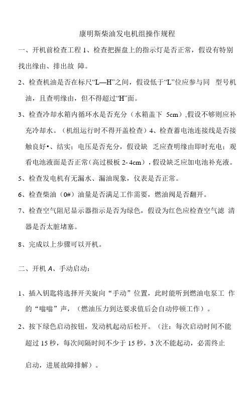
康明斯柴油发电机组操作规程一、开机前检查工程1、检查把握盘上的指示灯是否正常,假设有特别找出缘由、排出故障。
2、检查机油是否在标尺“L—H”之间,假设低于“L”位应参与同型号机油,且查明缘由,但不得超过“H”面。
3、检查冷却水箱内循环水是否充分(水箱盖下5cm),假设不够则应补充冷却水。
(机组运行时不得开盖检查)4、检查蓄电池连接线是否接触良好•、结实;电压是否充分,假设缺乏应查明缘由即时充电;观看电池液面是否正常(高过极板2- 4cm),假设缺乏应加电池补充液。
5、检查发电机有无漏水、漏油现象,仪表是否正常。
6、检查柴油(0#)油量是否满足工作需要,燃油阀是否翻开。
7、检查空气阻尼显示器指示是否为绿色,假设为红色应检查空气滤清器是否太脏堵塞。
8、完成以上步骤可以开机。
二、开机A、手动启动:1、插入钥匙将选择开关旋向“手动”位置,此时能听到燃油电泵工作的“嗡嗡”声,(燃油压力到达要求值后会自动停顿工作)。
2、按下绿色启动按钮,发动机起动后松开。
(注:每次启动时间不能超过15秒,每次间隔时间不少于15秒,3次不能起动,必需终止启动,进展故障排解)。
3、故障排解后再次启动前要进展故障复位操作,将选择开关旋到“停机” 位置,按下“故障复位”按钮,此时油压表、水温表应有指示。
4、重复启动步骤。
B、自动启动:1、插入钥匙将选择开关旋向“自动”位置,此时能听到燃油电泵工作的“嗡嗡”声,(燃油压力到达要求值后会自动停顿工作)。
2、将配电室“1B”柜中的发电机进线柜上的选择开关旋到“自动” 位置。
3、当市电停电时,发电机自动启动运行。
C、运行中留意事项:1、发电机组运转声音是否正常。
2、观看把握板上仪表参数是否在以下范围:电压表400V±5%;频率表50±0.5Hz;机油压力2vPS7bar,水温表74°C~97°C;充电电压28V 左右。
3、观看日用油箱的柴油存量是否充分。
柴油发电机安全操作规程(康明斯)
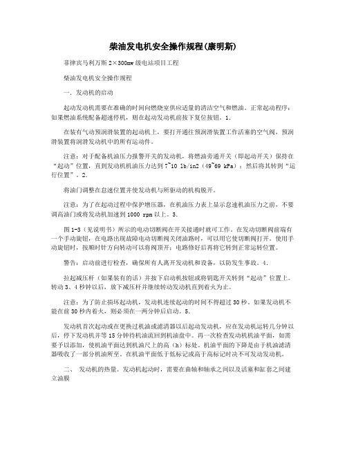
柴油发电机安全操作规程(康明斯)菲律宾马利万斯2×300mw级电站项目工程柴油发电机安全操作规程一.发动机的启动起动发动机需要在准确的时间向燃烧室供应适量的清洁空气和燃油。
正常起动程序:如果燃油系统配备超速停机,则在起动发动机前按下复位按钮。
1.在装有气动预润滑装置的起动机上,要打开通往预润滑装置工作活塞的空气阀,预润滑装置将润滑发动机中的所有运动件。
注意:对于配备机油压力报警开关的发动机,将燃油旁通开关(即起动开关)保持在“起动”位置,直到发动机机油压力达到7~10 lb/in2(49~69 kPa);然后将其转到“运行位置”。
2.将油门调整在怠速位置并使发动机与所驱动的机构脱开。
注意:为了在起动过程中保护增压器,在机油压力表上显示怠速机油压力之前,不要调高油门或将发动机加速到1000 rpm以上。
3.图1-3(见说明书)所示的电动切断阀在开关接通时就可工作。
在发动切断阀前端有一个手动旋钮,在电路出现故障电动切断阀关闭油路时,可以用它使切断阀打开。
使用手动旋钮时,按顺时针方向转动可以将阀顶开;电路修好后再将它转到正常运转位置。
警告:启动前进行检查,确保所有人离开发动机和设备,以防发生事故。
4.拉起减压杆(如果装有的话)并按下启动机按钮或将钥匙开关转到“起动”位置上。
转动3、4秒钟以后,放下减压杆并继续转动发动机直到着火为止。
注意:为了防止损坏起动机,发动机连续起动的时间不得超过30秒。
如果发动机不能在前30秒内着火,则必须在一两分钟后启动。
5.发动机首次起动或在更换过机油或滤清器以后起动发动机,应在发动机运转几分钟以后,停下发动机并等15分钟待机油流回到机油盘中。
再一次检查发动机机油平面,如需要予以添加,使机油平面达到机油尺上的高(h)标处。
机油平面的下降是由于机油滤清器吸收了一部分机油所至。
在机油平面低于低标记或高于高标记时决不可发动发动机。
二、发动机的热量。
发动机起动时,需要在曲轴和轴承之间以及活塞和缸套之间建立油膜一段时间。
康明斯发电机操作手册中文
操作手册发电机组型号GGHG, GGHH配备PowerCommand® Control控制器PCC 2100英文版公告号:928-0144B 03-2004中文版公告号: 928-0144B-CH2005年8月中国北京翻译目录章节 标题页码 重要安全注意事项 (iii)1引言..............................................................................................................1-1概述...........................................................................................................................1-1如何获得服务.............................................................................................................1-1 2技术规格.......................................................................................................2-1 3控制功能.......................................................................................................3-1概述...........................................................................................................................3-1起动前检查................................................................................................................3-1控制面板电源开/关模式.............................................................................................3-2前面板........................................................................................................................3-4起动...........................................................................................................................3-6停机...........................................................................................................................3-7菜单显示和按键.......................................................................................................3-11主菜单......................................................................................................................3-13调整默认设置...........................................................................................................3-15系统消息..................................................................................................................3-15控制器设置菜单.......................................................................................................3-16发动机菜单..............................................................................................................3-18发电机菜单..............................................................................................................3-20调整菜单..................................................................................................................3-22故障菜单..................................................................................................................3-24系统菜单..................................................................................................................3-26历史菜单..................................................................................................................3-28关于菜单..................................................................................................................3-30电源切换菜单...........................................................................................................3-32警告此产品发动机所排出的废气含有加州政府认为可导致癌症、先天缺陷或其他生殖损害的化学物质。
康明斯发电机操作手册中文

操作手册发电机组型号GGHG, GGHH配备PowerCommand® Control控制器PCC 2100英文版公告号:928-0144B 03-2004中文版公告号: 928-0144B-CH2005年8月中国北京翻译目录章节 标题页码 重要安全注意事项 (iii)1引言..............................................................................................................1-1概述...........................................................................................................................1-1如何获得服务.............................................................................................................1-1 2技术规格.......................................................................................................2-1 3控制功能.......................................................................................................3-1概述...........................................................................................................................3-1起动前检查................................................................................................................3-1控制面板电源开/关模式.............................................................................................3-2前面板........................................................................................................................3-4起动...........................................................................................................................3-6停机...........................................................................................................................3-7菜单显示和按键.......................................................................................................3-11主菜单......................................................................................................................3-13调整默认设置...........................................................................................................3-15系统消息..................................................................................................................3-15控制器设置菜单.......................................................................................................3-16发动机菜单..............................................................................................................3-18发电机菜单..............................................................................................................3-20调整菜单..................................................................................................................3-22故障菜单..................................................................................................................3-24系统菜单..................................................................................................................3-26历史菜单..................................................................................................................3-28关于菜单..................................................................................................................3-30电源切换菜单...........................................................................................................3-32警告此产品发动机所排出的废气含有加州政府认为可导致癌症、先天缺陷或其他生殖损害的化学物质。
康明斯发电机技术AGN 030 – 服务和维护说明书
Application Guidance Notes: Technical Information from Cummins Generator Technologies AGN 030 – Service and MaintenanceDESCRIPTIONSuitable service and maintenance are vital to the reliable operation of the alternator and the safety of anyone coming into contact with the alternator. The alternator should be inspected between scheduled maintenance, in line with inspection procedures and schedules provided by the manufacturer to identify any potential failure modes, signs of misuse or excessive wear and tear.An alternator specific Owner’s Manual (also known as Installation, Service and Maintenance Manual) is supplied with every alternator. The manuals are also published on the website. Each manual includes a Section on Service and Maintenance.The service activities are intended to maximise the life of the alternator but shall not vary, extend or change the terms of the manufacturer’s standard warranty or the customer’s obligation in that warranty.Each service interval is a guide only, developed on the basis that the alternator was installed and is operated in accordance with the manufacturer’s guidelines. If the alternator is located and/or operated in adverse or unusual environmental conditions, the service intervals may need to be more frequent. The alternator should be continually monitored between services to identify any potential failure modes, signs of misuse or excessive wear and tear. Recommended Service ScheduleThe recommended service schedule published in the manual shows the recommended service activities in table rows, grouped by alternator subsystem. Columns of the table show the typesof service activity, whether the alternator must be running, and the service levels. Service frequency is given in running hours or interval time, whichever is sooner. A cross (X) in the cells where a row intersects the column shows a service activity type and when it is required. An asterisk (*) shows a service activity done only when necessary.Service level documents referred to in the recommended service schedules can be purchased directly from Cummins Generator Technologies Customer Service Department, by telephone on +44 1780 484732 or by email: **************************************************. STAMFORD AlternatorsThe recommended service schedule for STAMFORD alternators can be found in Section 7 of the manual, with the following breakdown of sub-sections:Recommended Service ScheduleBearingsControlsCooling SystemCouplingRectifier SystemTemperature SensorsWindings.AvK AlternatorsThe recommended service schedule for AvK alternators can be found in Section 10 of the manual, with the following breakdown of sub-sections:Preventive ServicingSafety PrecautionsRecommended Service ScheduleServicing – General StructureVibrationServicing the Bearings and the Lubrication SystemGenerators with Bearing InsulationService WindingsServicing the Generators CoolerRepairs, Dismantling and Reassembly.Importance of Alternator MaintenanceThe maintenance programme is developed to meet the needs of different alternator designs. There are three types of maintenance strategies;∙Reactive maintenanceo Failure or abnormal operation.∙Preventive time based maintenanceo Time based maintenance.o Based on manufacturer’s experience.Predictive / condition based maintenanceo Maintenance based on actual measurements.A regular preventive maintenance schedule will ensure peak performance, maximize alternator life, maximized reliability and minimize breakdowns.INSTALLATION CONSIDERATIONSThe alternator must be installed in an accessible location with easy access to the main terminal box, bearing cap, air filter, louvers (inlet and outlet) and NDE/DE end brackets. The mentioned access points provide easy access to internal alternator components as shown in Figure 1. This will allow the execution of periodic inspections, local maintenance and removal of the alternator for external services.Figure 1: Internal alternator components that require periodic maintenance. Alternators LiftingDifferent alternator designs must be lifted by hooks or shackles attached to the lifting points (lugs or eyes). Chains of sufficient length, and a spreader bar if necessary must be used when lifting the alternators so as not to damage the terminal box, alternator parts and prevent the rotor from failing out on 1 bearing alternators as shown in Figure 2. When lifting entire Generating Set, the installation engineer must use specially designed Generating Set lifting points, and not alternator lifting lugs.Figure 2: Showing an example of the right and wrong alternator lifting methods. Mechanical CouplingInstallation engineers should follow the alternator manufacturer’s integration instructions provided in the Owner’s Manual. When coupling, the engineer should not attempt to rotate the alternator rotor by levering against the vanes of the cooling fan as shown in Figure 3 as the fan is not designed to withstand such forces and will be damaged. The holes of the coupling discs should be aligned with the flywheel holes by cranking the engine. Additional forces should not be put on the bearings while assembling the coupling half as it will damage the bearings.Figure 3: Alternator cooling fan vanes.SafetyIt is important to follow the alternator manufacturer’s general and local health and safety instructions. Incorrect installation, service or replacement of parts can result in severe equipment damage and personal injury. Only qualified individuals should perform electrical and mechanical component installations. Safety information signs are provided on the equipment to indicate hazards and emphasize instructions.Figure 4: Examples of the safety signs provided on an alternator. Environmental ConditionsAlternators installed in Generating Sets that are sited in arduous ambient environmental conditions may be susceptible to breakdown at their location site, if appropriate service and maintenance is not carried out. Ensuring reliable satisfactory service though, starts with careful consideration being given to the design of the ventilation systems that will be shared by both alternator and engine. Simplifying the considerations to just deciding to have a relatively simple canopy with large openings for the benefit of the engine and then considering the alternator satisfied by the fitting of low cost air filters will result in operating problems.Decisions at the Generating Set design stage about the Canopy design and airflow control must include discussions with the alternator manufacturer to ensure that the appropriate optional extra air-filter / louver kit is nominated or the IP rating of the alternator is increased and that a bespoke maintenance regime is implemented for the complete Generating Set.Refer to AGN072 – Environmental Conditions, for guidance on appropriate installation from the alternator manufacturer’s viewpoint.Alternators in Coastal LocationsFor example; an RTG Crane application is a quite unique situation. For reasons of making the alternator output characteristics suitable to power the Crane’s drive motor, combined with the duty cycle of the variable crane motor load, the alternator is usually operating with quite low winding temperatures. Whilst this low temperature situation would normally be considered to be beneficial, it does introduce a problem when the operating environment is a salt laden with a high humidity. The accepted winding temperature at which moisture is driven from the windings is some 95o C and experience is showing that RTG applications do not achieve this. So we have a winding contaminated by a salt laden atmosphere, combined with the dust and pollutants around a working dockside, plus RIC engined port vehicles adding exhaust by-products to this winding contamination problem. Add to this the humidity and moisture associated with local weather conditions, forming surface moisture on the alternator’s outhang, a winding that is not getting hot enough to drive the moisture off and we have created a winding insulation system with much reduced ‘barrier’ capabilities.The above considers the contaminants that weaken the winding insulation system. The following explains the additional electrical stresses associated with the Variable Speed Drive units used to power the various crane movements.These VSD’s are Non Linear Loads [NLL], with quite high levels of harmonic distortion. The resulting harmonic voltage distortion results in transient voltage conditions that may well be twice the peak value that the alternator would experience under normal linear load conditions.These high transient voltage spikes stress the electrical insulation system, with which a clean uncontaminated winding insulation system can cope. But a contaminated winding will find such transient voltage spikes difficult to contain, followed inevitable by the breakdown of the insulation barrier and winding short circuit.The decision to have the new alternator fitted with IP44 inlet louvers will ensure that whilst the alternator is running, the inlet cooling air is being filtered and moisture droplets are being removed by the Premaberg filter system.However the IP44 filter assembly is not really addressing all the problems of the location being in a coastal, salt laden atmosphere. The problem with salt is that it will form a moisture absorbing film of contamination on the alternator’s winding. When the alternator is working and the windings are hot, the moisture is driven off the windings surface and the insulation resistance - IR - will be high enough to ensure that no insulation breakdown or surface tracking occurs. However; as soon as the Generating Set is stopped, the alternator’s local environment becomes extremely humid, it is at this point the hygroscopic layer of salt that has formed on the windings will absorb moisture and this will result in the windings IR value being reduced to a low level and so, an inability to insulate/isolate phase to phase and phase to earth. Therefore, when the Generating Set is next started and the alternator excites to the normal working voltage - electrical pressure - there is a real risk that an insulation failure will occur as a result of insulation breakdown initiated by surface tracking.The ideal solution is to filter the salt from Generating Set cooling air. But the practicalities must include control of the humidity level of the alternator’s environment and this involves far more than the fitting of an alternator anti-condensation heater.The most successful schemes involve a fan heater bl owing several kW’s of hot air around the Generating Set ‘chamber’ to keep the humidity RH% as low as possible. Obviously, this needs an electrical power supply when the Generating Set is not running and so may well not be an easy option.There may be a way of running-on the Generating Set after its programmed service duty. This would be in a way devised to keep hot dry air circulating whilst the whole Generating Set area temperature is gradually reduced to stop the sudden increase in RH% that occurs around Generating S ets when they are stopped and left trapped in their ‘sweat box’ canopies.It could be that Generating Set’s are operating in parallel, or a Generating Set is operating in parallel with a mains supply. This then suggests an option to introduce some Generating Set environment control, because it would seem that there is always an electrical supply available. We cannot rule out that the stresses associated with miss-paralleling, or the instability of the local mains supply e.g.; micro-interruptions, will damage insulation systems and promote failures. But if the site history is one of winding failures occurring at the point/moment of starting the Generating Set ready to put the unit back into service then, from experience, we would consider saline contamination is the prime culprit.MAINTENANCE OF THE WINDING INSULATION SYSTEMThe only way to check on the condition of the winding insulation system, is by introducing a regular procedure to check the stator winding Insulation Resistance (IR) value and although not normal practice for a low voltage scheme, the Polarisation Index [PI] should be measured too, if the alternator is installed in any challenging environment. This check of IR and PI need only be carried out to the stator winding. The spinning of the rotor and the fact that it operates at low voltages means that it is not, as much, at risk.Refer to AGN015 – Testing Winding Insulation Systems for details of IR and PI testing.At the first sign that the IR and PI are low, the alternator stator winding must be cleaned.T he exciter field is another ‘at risk’ component and the fact that it operates with dc. means that it has a high risk factor due to its operation with fixed polarisation. If the exciter field insulation fails it will also take out the AVR.Cleaning windingsIf cleaning of the windings becomes necessary, then the preferred method is to completely strip the alternator to enable a thorough inspection and then a washing process, which will result in dirt removal by encouraging a washing-out of dirt by an action that will not result in the dirt being forced further into the winding assembly. The washing medium should be clean hot water applied from a directional nozzle at a pressure not exceeding 3bar.At no point should the winding insulation be subjected to a jet of water pressure that is deforming the insulation materials.For extremely oily contaminants, an alternative method is to use a hot pressure wash - not exceeding 3bar – with an added solvent based biodegradable cleaner of neutral pH. Note: ‘Autosmart’ and Aquawash’ are trade names of such biodegradable cleaners.Water-based Alkaline Detergents should not be used for cleaning as they contain ‘wetting agents’ that leave contaminants - in the form of salts - on the winding surfaces. These contaminants are hygroscopic and therefore readily absorb moisture, which will lower the insulation resistance and promote surface tracking.Caution: Inappropriate or badly executed cleaning methods will leave contamination embedded in the winding crevices and this local contamination will promote degradation of the insulation system.After the cleaning process, the windings must be slowly[over several hours] heated to at least 100degC in a thorough drying out procedure of perhaps twelve to twenty four hours. The insulation resistance [IR], phase to phase, and phase to earth, must be measured during this process.Refer to the alternator’s Owner’s Manual (Installation, Service & Maintenance Manual) for the drying out procedures and the IR test procedure, including the values, in Mega-Ohms, that thewinding must achieve before the winding IR can be said to be high enough for the wound assembly to be considered a serviceable unit.Once the windings have been cleaned and the insulation resistance improved to what is considered to be a satisfactory level, the clean and dry windings should be treated with an appropriate ‘over-coating’ electrical anti-tracking resin / varnish. This treatment will offer protection from further immediate in-service recontamination of the winding surface. The chosen anti-tracking material should be of the same insulation thermal rating as the alternator’s insulation system - Class ‘F’ or Class ‘H’.Checks must also be made to ensure that the electrical anti-tracking resin / varnish will adhere to the windings original impregnation materials.Application Guidance Notes are for information purposes only. Cummins Generator Technologies reserves the right to change the contents of Application Guidance Notes without notice and shall not be held responsible for any subsequent claims in relation to the content.。
康明斯发动机操作及维护保养要点
工程机械频道1、冷却系统新机启动前要加注冷却液。
加注时,应打开发动机上部冷却系统的放气阀门,缓慢地将冷却液从散热水箱的加水口加入到发动机中,直至没有气泡再从放气阀门中排出为止。
冷却液应加注至散热水箱加水口颈部下方,不宜过满。
加注完毕后,将放气阀门关闭,并将水滤器安装座上的截门打开,以便dca4添加剂能够混合进入冷却系统中。
冷却系统所用冷却液主要应由纯净水、防冻液及dca4添加剂3种成分构成,每升冷却液含50%的纯净水、50%的防冻液和0.5单位的dca4添加剂。
配好的冷却液一年四季均可使用,并且可以连续使用两年。
纯净水由于经过净化,因而可避免形成水垢。
防冻液系指工业用的乙烯乙二醇或丙烯乙二醇,可以降低水的冰点及提高水的沸点。
防冻液的浓度应为40%。
68%,浓度过高或过低均会影响冷却液的防冻能力。
在大多数气候条件下,推荐使用的防冻液浓度为50%,此时冷却液的冰点可达—33cc。
dca4添加剂可在水系统内表面形成一层保护膜,以防止缸套和机体产生穴蚀及阻止沉淀物堆积。
康明斯c系列以上的发动机都安有水滤器,水滤器除了有过滤介质外,内部还含有dca4添加剂。
dca4添加剂的浓度一般要求保持为每升水中含有0.32~0.79单位,可以通过dca4检测包来检测。
2、润滑系统新机启动前应通过加油口加注机油。
加注时发动机应置于水平位置并注意观察油位的变化。
加完油要等一会儿再看油标尺上的油位,即等机油都流入油底壳后所看到的油位才是正确值。
每个机油滤清器处都应加满清洁机油,然后才能装在发动机上。
选择机油时,一要选择合适的机油粘度,二要符合美国石油协会(ah)阶性能等级。
康明斯发动机要求使用多级粘度的机油,因为多级粘度机油适合的工作温度范围较广且消耗率比单级粘度机油约低30%。
机油的性能等级代表了机油添加剂的水平,对于重载荷的发动机,起保护作用的主要是机油中的添加剂,由于添加剂随着时间的延续会逐渐消耗,只有选用足够等级的机油,才能保证发动机在整个换油周期内都能得到可*的保护。
康明斯发电机操作说明书(维护手册)

康明斯电力系统服务手册柴油发电机组(DF系列/PCC并联控制系统)中文版公告号:EA-MS-5700(英文版公告号:900-0519 7-97)目录章节名称页次安全守则 (iii)1 序言关于本手册....................................................................................................1-1测试设备........................................................................................................1-1如何得到服务.................................................................................................1-1系统概述........................................................................................................1-2发电机组控制功能..........................................................................................1-22 控制操作概述...............................................................................................................2-1安全考虑........................................................................................................2-1操作顺序........................................................................................................2-2PCC接电/备用模式.......................................................................................2-2前端面板........................................................................................................2-4功能显示和按键.............................................................................................2-6主功能...........................................................................................................2-6发动机功能....................................................................................................2-8发电机功能..................................................................................................2-103 电路板和模块概述...............................................................................................................3-1数字电路板(A32).......................................................................................3-3发动机界面电路板(A31)............................................................................3-4模拟电路板(A33).......................................................................................3-6数字显示电路板(A35)................................................................................3-7用户界面电路板(A34)................................................................................3-8电压/电流互感器(PT/CT)电路板(A36).................................................3-10母排电压互感器电路板(A39)...................................................................3-11发电机组通信模块(A39)..........................................................................3-12调压器输出模块(A37)..............................................................................3-17调速器输出模块(A38)..............................................................................3-18最快达标侦测传感器....................................................................................3-194 故障排除概述...............................................................................................................4-1安全考虑........................................................................................................4-1状态指示灯....................................................................................................4-2控制系统复位.................................................................................................4-2报警和报警停机代码......................................................................................4-3PCC机油压力报警和报警停机设定..............................................................4-13故障排除步骤...............................................................................................4-14PCC保险丝.................................................................................................4-54负载分配控制故障排除步骤..........................................................................4-55ⅰ5 控制盘维修及其标定概述..............................................................................................................5-1电路板拆卸/更换............................................................................................5-1初次起动功能设定.........................................................................................5-4调整功能.......................................................................................................5-6设定和标定功能.............................................................................................5-8标定程序.....................................................................................................5-24附件箱控制部件...........................................................................................5-27发动机传感器..............................................................................................5-40发动机转速传感器(MPU)安装.................................................................5-44电流互感器(CT)安装...............................................................................5-45 6 发电机维修发电机测试....................................................................................................6-1绝缘阻抗和极化指数测试...............................................................................6-2绕组干燥步骤................................................................................................6-4发电机/PCC控制盘隔离型母排设定..............................................................6-4励磁机定子....................................................................................................6-5励磁机整流电路板(旋转整流器总成)..........................................................6-6励磁机转子....................................................................................................6-7主转子(发电机磁场)..................................................................................6-8主定子...........................................................................................................6-9测试永久励磁发电机(PMG)......................................................................6-11发电机分解..................................................................................................6-12发电机重新装配...........................................................................................6-21 7 日用油箱燃油输送泵及其控制器操作..............................................................................................................7-2导线连接.......................................................................................................7-4燃油输送泵马达连接......................................................................................7-6测试浮子开关总成.........................................................................................7-78 系统初次起动概述..............................................................................................................8-1起动步骤.......................................................................................................8-1设备应用审查................................................................................................8-2各发电机组起动.............................................................................................8-2系统手动操作................................................................................................8-4系统自动操作................................................................................................8-7黑起动(Black Start)测试............................................................................8-8测试报告和验收.............................................................................................8-8现场电力系统应用审查(柴油机/600 VAC及以下)..........................................................................8-9 9 电路图概述..............................................................................................................9-1ⅱ安全守则操作发电机组之前,需先认真阅读操作手册,以熟悉你的设备,只有正确地操作和维护设备,才能保证安全、有效地运行,许多事故发生的原因是没有遵循基本规则和安全守则造成的。
- 1、下载文档前请自行甄别文档内容的完整性,平台不提供额外的编辑、内容补充、找答案等附加服务。
- 2、"仅部分预览"的文档,不可在线预览部分如存在完整性等问题,可反馈申请退款(可完整预览的文档不适用该条件!)。
- 3、如文档侵犯您的权益,请联系客服反馈,我们会尽快为您处理(人工客服工作时间:9:00-18:30)。
康明斯电力系统服务手册柴油发电机组(DF系列/PCC并联控制系统)中文版公告号:EA-MS-5700(英文版公告号:900-0519 7-97)目录章节名称页次安全守则 (iii)1 序言关于本手册....................................................................................................1-1测试设备........................................................................................................1-1如何得到服务.................................................................................................1-1系统概述........................................................................................................1-2发电机组控制功能..........................................................................................1-22 控制操作概述...............................................................................................................2-1安全考虑........................................................................................................2-1操作顺序........................................................................................................2-2PCC接电/备用模式.......................................................................................2-2前端面板........................................................................................................2-4功能显示和按键.............................................................................................2-6主功能...........................................................................................................2-6发动机功能....................................................................................................2-8发电机功能..................................................................................................2-103 电路板和模块概述...............................................................................................................3-1数字电路板(A32).......................................................................................3-3发动机界面电路板(A31)............................................................................3-4模拟电路板(A33).......................................................................................3-6数字显示电路板(A35)................................................................................3-7用户界面电路板(A34)................................................................................3-8电压/电流互感器(PT/CT)电路板(A36).................................................3-10母排电压互感器电路板(A39)...................................................................3-11发电机组通信模块(A39)..........................................................................3-12调压器输出模块(A37)..............................................................................3-17调速器输出模块(A38)..............................................................................3-18最快达标侦测传感器....................................................................................3-194 故障排除概述...............................................................................................................4-1安全考虑........................................................................................................4-1状态指示灯....................................................................................................4-2控制系统复位.................................................................................................4-2报警和报警停机代码......................................................................................4-3PCC机油压力报警和报警停机设定..............................................................4-13故障排除步骤...............................................................................................4-14PCC保险丝.................................................................................................4-54负载分配控制故障排除步骤..........................................................................4-55ⅰ5 控制盘维修及其标定概述..............................................................................................................5-1电路板拆卸/更换............................................................................................5-1初次起动功能设定.........................................................................................5-4调整功能.......................................................................................................5-6设定和标定功能.............................................................................................5-8标定程序.....................................................................................................5-24附件箱控制部件...........................................................................................5-27发动机传感器..............................................................................................5-40发动机转速传感器(MPU)安装.................................................................5-44电流互感器(CT)安装...............................................................................5-45 6 发电机维修发电机测试....................................................................................................6-1绝缘阻抗和极化指数测试...............................................................................6-2绕组干燥步骤................................................................................................6-4发电机/PCC控制盘隔离型母排设定..............................................................6-4励磁机定子....................................................................................................6-5励磁机整流电路板(旋转整流器总成)..........................................................6-6励磁机转子....................................................................................................6-7主转子(发电机磁场)..................................................................................6-8主定子...........................................................................................................6-9测试永久励磁发电机(PMG)......................................................................6-11发电机分解..................................................................................................6-12发电机重新装配...........................................................................................6-21 7 日用油箱燃油输送泵及其控制器操作..............................................................................................................7-2导线连接.......................................................................................................7-4燃油输送泵马达连接......................................................................................7-6测试浮子开关总成.........................................................................................7-78 系统初次起动概述..............................................................................................................8-1起动步骤.......................................................................................................8-1设备应用审查................................................................................................8-2各发电机组起动.............................................................................................8-2系统手动操作................................................................................................8-4系统自动操作................................................................................................8-7黑起动(Black Start)测试............................................................................8-8测试报告和验收.............................................................................................8-8现场电力系统应用审查(柴油机/600 VAC及以下)..........................................................................8-9 9 电路图概述..............................................................................................................9-1ⅱ安全守则操作发电机组之前,需先认真阅读操作手册,以熟悉你的设备,只有正确地操作和维护设备,才能保证安全、有效地运行,许多事故发生的原因是没有遵循基本规则和安全守则造成的。