科研实验室电池测试系统BT-2018A精致四量程款
恩智浦半导体BATT-18EMBERATOR 18芯电池组模拟器用户手册说明书
UM11817Introduction to 18-cell slider battery pack emulatorRev. 1 — 17 February 2023User manualIntroduction to 18-cell slider battery pack emulatorIntroduction to 18-cell slider battery pack emulator 1 IntroductionThe BATT-18EMULATOR board can emulate a multi-cell battery pack that can be easily hooked-up to the evaluation boards for MC33774 18-cell battery cell controllers (BCCs):•RD33774ADSTEVB - distributed board with single MC33774•RD33774CNT3EVB - centralized board with three MC33774The user can connect the BATT-18EMULATOR board for a quick evaluation of NXP BCC ICs, or to help the users in their software development. These boards basically provide a very intuitive way:•To change the voltage across any of the 18 cells of an emulated battery pack•To change the voltage across some analog inputs of the BCC IC that are typically used as temperature sensorsFigure 1. BATT-18EMULATOR2 Getting started2.1 Kit contents/packing listThe kit contents include:•BATT-18EMULATOR, 18-cell slider battery pack emulator•25 W AC-DC adapter with +5 VDC/5 A single output - DC plug type P1J (2.1 × 5.5 × 11 mm), tuning fork type, center positive•Adapter cable DC plug 2.1 × 5.5 × 11 mm to 2.5 × 5.5 × 9.5 mmIntroduction to 18-cell slider battery pack emulator 3 Getting to know the hardware3.1 Board features•18 slider potentiometers to adjust the cells voltage between 1.2 V and 3.3 V. The maximum total voltage has been limited to 60 V.•Three cells voltage can be inverted to apply voltages from −1.2 V to −3.3 V•Maximum current capability per channel: 200 mA•Three connectors for MC33774 evaluation boards connections•Temperature sensor output voltage can vary from 0 V to +4.95 V to simulate negative temperature coefficient (NTC) sensor3.2 Board functionsThe board has been designed and optimized for the operating conditions described in Table 1 and Table 2. Usage of the board beyond these conditions can lead to malfunction and damage.Table 1. Limiting valuesIn accordance with the Absolute Maximum Rating System (IEC 60134).[1]The maximum input supply current depends on the setup: number of boards connected, cells voltage, activated cell balancing channels; seeSection 3.3.3.[1]With jumpers setting, it is possible to get negative voltages from −3.3 V to −1.2 V for cells 13, 8 and 4; see Section 3.3.4.Introduction to 18-cell slider battery pack emulator 3.3 Board functional descriptionFigure 2. BATT-18EMULATOR board elements3.3.1 DescriptionEach cell emulation is made of a 5 V to 5 V unregulated isolated DC-DC converter and an adjustable regulator. The regulator output voltage is set thanks to a voltage slider. Minimum voltage is 1.2 V and maximum is set to 3.3 V.3.3.2 Connection and configurationThe emulator board requires a 5 V DC power supply with 5 A current capability. The power supply is connected to the board via J3 a Ø2.5 mm jack connector or using the 2 mm bananas J2(+) and J1(−). The center pinis connected to the positive voltage and the ring terminal to the ground. The input of the board is 5 A fuse protected. An LED allows the user to check that the board is powered up. If the voltage is present on the jack connector but the LED is off, then check the fuse F1.Up to three evaluation boards RD33774ADSTEVB or one RD33774CNT3EVB can be connected using connectors J4, J5, and J6 with no specific order.3.3.3 Current consumptionThe slider pack should be supplied with a +5 V AC-DC adapter or with a lab supply. The required supply current depends on several parameters described below.With no board connected, the default supply current on the 5 V primary is around 500 mA [19 × 28 mA (DC-DC typ supply current)].One RD33774ADSTEVB board, communicating, no balancing activated, consumes around 10.5 mA. Then the total supply current required on the 5 V primary is around 700 mA [500 mA + (19 × 10.5 mA)].If three boards are connected, then the supply current is 500 mA + (3 × 19 × 10.5 mA) = 1 A.If cell balancing is activated, the primary current depends on the cell voltage, the balancing resistance, and the number of balancing metal-oxide-semiconductor field-effect transistor (MOSFET) activated.Introduction to 18-cell slider battery pack emulator On RD33774ADSTEVB, the balancing resistance is 22 Ω per cell balancing channel. With V cell = 3.3 V, the peak balancing current is 150 mA peak, 75 mA average assuming a 50 % duty cycle. If N cell balancing MOSFETs are activated, then N × 75 mA are added to the primary current needed. If one board is connected and all18 cell balancing MOSFETs are activated, then the total current is 700 mA + 18 × 75 mA = 2 A. Each individual channel (200 mA of current capability) has to provide 10.5 mA + 75 mA averaged or 10.5 mA + 150 mA peak. Note: The current is limited to 180 mA per channel. If several boards are connected, it is recommended toavoid to activate same cell balancing channels at the same time on all the boards.3.3.4 Cell polarity selectionThree pairs of jumpers allow the polarity to be reversed for cell polarities for cell4 (C5M − C4M), cell8(C9M − C8M) and cell13 (C14M − C13M) therefore providing voltages between −1.2 V and −3.3 V; see Table 3.Note: Jumper selections should be done prior to supplying the BATT-18EMULATOR. Adjacent cell voltages are impacted when changing the polarities.3.3.5 External voltage injectionThe three jumpers can also be used as injection points to inject voltages above slider ranges: −1.2 V < V inj <+1.2 V or 3.3 V < V inj, typically to evaluate MC33774 cell terminal measurements at very low voltage (busbars) or a high-voltage cell.As example, to inject a voltage between C5M and C4M, remove jumper J8, keep jumper J7 1-2, and connect a floating supply between J8-2 and J7-1 or 2. Do not exceed maximum ratings and keep cell voltage in the range −5 V to +5 V.3.3.6 Temperature sensor simulationA separate slider allows the variation of the voltage across the temperature sensors.The temperature sensor output voltage can vary from 0 V to +4.95 V. It can mimic the temperaturevariation from −48 °C to +200 °C of a 10 kΩ NTC sensor. This output voltage is connected to four different general‑purpose input/output (GPIO) on the MC33774 (GPIO 1, 2, 7, 8) configured as ratiometric inputs with10 kΩ pull‑up resistors to VAUX (3.3 V typ.).3.4 MC33774 board connectionsThree 32 pins connectors (JAE Electronics MX34032NF2) J4, J5, J6 are connected in parallel as perthe following schematic Figure 3. Up to three boards (for example, RD33774ADSTEVB) or one boardRD33774CNT3EVB can be connected on any of these connectors.Introduction to 18-cell slider battery pack emulator Slider cell 0 is setting the voltage between C0M (cell0M) and C1M (cell0P), slider cell 1 is setting the voltage between C1M (cell1M) and C2M (cell1P), and so on, slider cell 17 is setting the voltage between C17M(cell17M) and C17P (cell17P).C17P-PWR and GND (pin 21) are used to supply the RD33774ADSTEVB and are separated from C17P andC0M respectively to avoid any voltage drop due to the current consumption of the evaluation boards.The slide temperature sensor is connected on pin 17 to pin 20 (NTC1, 2, 7 and 8 for RD33774DSTEVB).Figure 4. BATT-18EMULATOR connected to three RD33774DSTEVBIntroduction to 18-cell slider battery pack emulator 4 SchematicFigure 5. SchemaIntroduction to 18-cell slider battery pack emulator 5 Legal information5.1 DefinitionsDraft — A draft status on a document indicates that the content is still under internal review and subject to formal approval, which may resultin modifications or additions. NXP Semiconductors does not give any representations or warranties as to the accuracy or completeness of information included in a draft version of a document and shall have no liability for the consequences of use of such information.5.2 DisclaimersLimited warranty and liability — Information in this document is believed to be accurate and reliable. However, NXP Semiconductors does not give any representations or warranties, expressed or implied, as to the accuracy or completeness of such information and shall have no liability for the consequences of use of such information. NXP Semiconductors takes no responsibility for the content in this document if provided by an information source outside of NXP Semiconductors.In no event shall NXP Semiconductors be liable for any indirect, incidental, punitive, special or consequential damages (including - without limitation -lost profits, lost savings, business interruption, costs related to the removal or replacement of any products or rework charges) whether or not such damages are based on tort (including negligence), warranty, breach of contract or any other legal theory.Notwithstanding any damages that customer might incur for any reason whatsoever, NXP Semiconductors’ aggregate and cumulative liability towards customer for the products described herein shall be limited in accordance with the Terms and conditions of commercial sale of NXP Semiconductors.Right to make changes — NXP Semiconductors reserves the right to make changes to information published in this document, including without limitation specifications and product descriptions, at any time and without notice. This document supersedes and replaces all information supplied prior to the publication hereof.Applications — Applications that are described herein for any of these products are for illustrative purposes only. NXP Semiconductors makes no representation or warranty that such applications will be suitable for the specified use without further testing or modification.Customers are responsible for the design and operation of their applications and products using NXP Semiconductors products, and NXP Semiconductors accepts no liability for any assistance with applications or customer product design. It is customer’s sole responsibility to determine whether the NXP Semiconductors product is suitable and fit for the customer’s applications and products planned, as well as for the planned application and use of customer’s third party customer(s). Customers should provide appropriate design and operating safeguards to minimize the risks associated with their applications and products.NXP Semiconductors does not accept any liability related to any default, damage, costs or problem which is based on any weakness or defaultin the customer’s applications or products, or the application or use by customer’s third party customer(s). Customer is responsible for doing all necessary testing for the customer’s applications and products using NXP Semiconductors products in order to avoid a default of the applicationsand the products or of the application or use by customer’s third party customer(s). NXP does not accept any liability in this respect.Terms and conditions of commercial sale — NXP Semiconductors products are sold subject to the general terms and conditions of commercial sale, as published at /profile/terms, unless otherwise agreed in a valid written individual agreement. In case an individual agreement is concluded only the terms and conditions of the respective agreement shall apply. NXP Semiconductors hereby expressly objects to applying the customer’s general terms and conditions with regard to the purchase of NXP Semiconductors products by customer.Suitability for use in automotive applications — This NXP product has been qualified for use in automotive applications. If this product is usedby customer in the development of, or for incorporation into, products or services (a) used in safety critical applications or (b) in which failure could lead to death, personal injury, or severe physical or environmental damage (such products and services hereinafter referred to as “Critical Applications”), then customer makes the ultimate design decisions regarding its products and is solely responsible for compliance with all legal, regulatory, safety, and security related requirements concerning its products, regardless ofany information or support that may be provided by NXP. As such, customer assumes all risk related to use of any products in Critical Applications and NXP and its suppliers shall not be liable for any such use by customer. Accordingly, customer will indemnify and hold NXP harmless from any claims, liabilities, damages and associated costs and expenses (including attorneys’ fees) that NXP may incur related to customer’s incorporation of any product in a Critical Application.Export control — This document as well as the item(s) described herein may be subject to export control regulations. Export might require a prior authorization from competent authorities.Evaluation products — This product is provided on an “as is” and “with all faults” basis for evaluation purposes only. NXP Semiconductors, its affiliates and their suppliers expressly disclaim all warranties, whether express, implied or statutory, including but not limited to the implied warranties of non-infringement, merchantability and fitness for a particular purpose. The entire risk as to the quality, or arising out of the use or performance, of this product remains with customer.In no event shall NXP Semiconductors, its affiliates or their suppliersbe liable to customer for any special, indirect, consequential, punitiveor incidental damages (including without limitation damages for loss of business, business interruption, loss of use, loss of data or information, and the like) arising out the use of or inability to use the product, whether or not based on tort (including negligence), strict liability, breach of contract, breach of warranty or any other theory, even if advised of the possibility of such damages.Notwithstanding any damages that customer might incur for any reason whatsoever (including without limitation, all damages referenced above and all direct or general damages), the entire liability of NXP Semiconductors,its affiliates and their suppliers and customer’s exclusive remedy for all of the foregoing shall be limited to actual damages incurred by customer based on reasonable reliance up to the greater of the amount actually paid by customer for the product or five dollars (US$5.00). The foregoing limitations, exclusions and disclaimers shall apply to the maximum extent permitted by applicable law, even if any remedy fails of its essential purpose.Translations — A non-English (translated) version of a document, including the legal information in that document, is for reference only. The English version shall prevail in case of any discrepancy between the translated and English versions.Security — Customer understands that all NXP products may be subject to unidentified vulnerabilities or may support established security standards or specifications with known limitations. Customer is responsible for the design and operation of its applications and products throughout their lifecyclesto reduce the effect of these vulnerabilities on customer’s applicationsand products. Customer’s responsibility also extends to other open and/or proprietary technologies supported by NXP products for use in customer’s applications. NXP accepts no liability for any vulnerability. Customer should regularly check security updates from NXP and follow up appropriately. Customer shall select products with security features that best meet rules, regulations, and standards of the intended application and make the ultimate design decisions regarding its products and is solely responsiblefor compliance with all legal, regulatory, and security related requirements concerning its products, regardless of any information or support that may be provided by NXP.NXP has a Product Security Incident Response Team (PSIRT) (reachableat *************) that manages the investigation, reporting, and solution release to security vulnerabilities of NXP products.Introduction to 18-cell slider battery pack emulatorNXP — wordmark and logo are trademarks of NXP B.V.5.3 TrademarksNotice: All referenced brands, product names, service names, andtrademarks are the property of their respective owners.Introduction to 18-cell slider battery pack emulatorTablesTab. 1.Limiting values (4)Tab. 2.Electrical characteristics (4)Tab. 3.Cell voltage polarity selection (6)FiguresFig. 1.BATT-18EMULATOR (3)Fig. 2.BATT-18EMULATOR board elements (5)Fig. 3.Cell connector schematic ..................................7Fig. 4.BATT-18EMULATOR connected to threeRD33774DSTEVB (7)Fig. 5.Schema (8)UM11817All information provided in this document is subject to legal disclaimers.© 2023 NXP B.V. All rights reserved. User manual Rev. 1 — 17 February 202311 / 12Introduction to 18-cell slider battery pack emulatorContents1Introduction (3)2Getting started (3)2.1Kit contents/packing list (3)3Getting to know the hardware (4)3.1Board features (4)3.2Board functions (4)3.3Board functional description (5)3.3.1Description (5)3.3.2Connection and configuration (5)3.3.3Current consumption (5)3.3.4Cell polarity selection (6)3.3.5External voltage injection (6)3.3.6Temperature sensor simulation (6)3.4MC33774 board connections (6)4Schematic (8)5Legal information (9)Please be aware that important notices concerning this document and the product(s)described herein, have been included in section 'Legal information'.© 2023 NXP B.V.All rights reserved.For more information, please visit: Date of release: 17 February 2023。
星恒电池智能测试设备说明书
星恒电池智能测试设备说明书摘要:1.星恒电池智能测试设备说明书概述2.设备主要功能和特点3.设备操作步骤4.设备维护与安全注意事项5.设备常见问题解答正文:一、星恒电池智能测试设备说明书概述星恒电池智能测试设备是一款专业用于检测电池性能的设备,凭借其出色的功能和便捷的操作,成为电池研发、生产和维修领域的理想选择。
本说明书旨在帮助用户更好地了解和操作该设备,确保其发挥最佳性能。
二、设备主要功能和特点1.高精度检测:星恒电池智能测试设备具备高精度的电压、电流检测功能,能够准确测量电池的各项性能参数。
2.多功能测试:设备支持多种电池类型测试,包括锂离子电池、镍氢电池、镍镉电池等,满足不同用户需求。
3.自动化操作:设备具备自动化测试功能,用户只需设置参数,设备即可自动完成测试过程。
4.数据存储与分析:设备能够将测试数据存储在系统中,用户可通过系统进行数据分析和比较,便于优化产品性能。
三、设备操作步骤1.开机准备:确保设备连接到电源,并打开电源开关。
2.参数设置:根据需要测试的电池类型和性能参数,设置相应的测试参数。
3.放置电池:将待测电池放入设备测试槽中,并确保接触良好。
4.开始测试:点击开始测试按钮,设备将自动进行测试。
5.结束测试:测试完成后,设备将自动停止并弹出测试结果。
四、设备维护与安全注意事项1.定期检查设备连接线,确保连接良好,避免因接触不良导致的设备故障。
2.设备工作过程中,请勿触摸测试槽,以免触电。
3.设备非专业人员不得拆卸,如需维修请联系售后服务。
4.请勿在设备附近放置易燃易爆物品,确保设备工作环境安全。
五、设备常见问题解答1.问:灯不亮,无法开机:请检查电源线是否连接好,电源开关是否打开。
2.问:测试数据不准确:请检查测试参数设置是否正确,确保电池接触良好。
3.问:设备无法自动停止:请检查设备连接线是否松动,或联系售后服务。
通过以上详细介绍,相信您已对星恒电池智能测试设备有了充分的了解。
BT-100电池加载测试器说明书

00-99-000437/0804
WARNING: Handling the cord on this product or cords associated with accessories sold with this product, will expose you to lead, a chemical known to the State of California to cause cancer and birth defects or other reproductive harm. Wash hands after handling.
Weak or Bad, But Needle Remains Steady (Yellow or Red)
Battery capacity is not satisfactory. Battery may be either defective or not fully charged. Check specific gravity to determine which condition exists. If charging does not bring specific gravity to full charge level, battery should be replaced.
This limited warranty is void if the product is misused, subjected to careless handling, or repaired by anyone other than the manufacturer or its authorized representative.
科研实验室电池测试系统BT-2018A精致四量程款

科研实验室电池测试系统BT-2018A精致四量程款
科研实验室电池测试系统
BT-2018A(精致四量程款)
一、技术参数5V100mA四量程
适用于:大专院校、科研机构、电池材料生产及电池生产企业对扣式电池、模拟电池、半电池、三电极电池、超级电容器等相关电化学方面的研究测试。
测试项目:充放电详细数据、循环寿命、充放电曲线、充放电效率、比容量、比能量、直流电阻、漏电(自放电)电流等项目。
BT-2018A(精致四量程款)
三、LANB TS电池测试系统专用软件
LANB TS电池测试系统控制软件和数据分析软件借鉴了国外同类产品的优点,结合国内用户
的使用习惯,我们做了全新的开发。
软件采用.NET架构,WIN10风格、平面化设计、运算速度更流畅,数据处理更强大,而且编程方案可编辑等特点。
软件启动画面
LANB TS电池测试系统监控界面
测试方案编辑界面
数据分析软件界面。
LAND电池测试系统说明书LAND蓝电系列电池测试系统用户使用指南
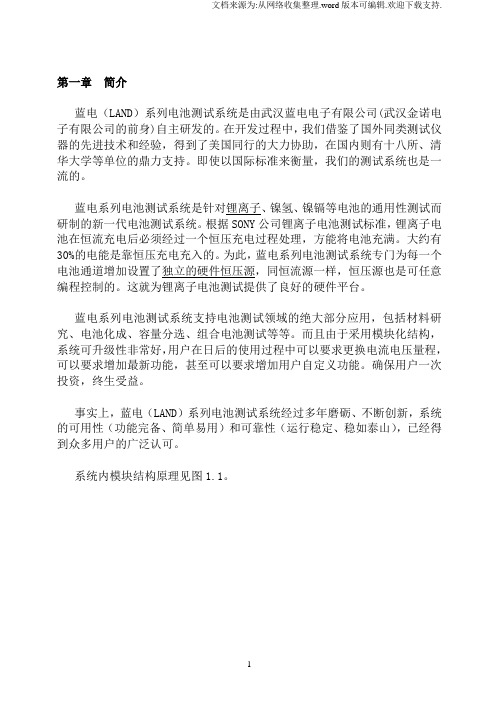
第一章简介蓝电(LAND)系列电池测试系统是由武汉蓝电电子有限公司(武汉金诺电子有限公司的前身)自主研发的。
在开发过程中,我们借鉴了国外同类测试仪器的先进技术和经验,得到了美国同行的大力协助,在国内则有十八所、清华大学等单位的鼎力支持。
即使以国际标准来衡量,我们的测试系统也是一流的。
蓝电系列电池测试系统是针对锂离子、镍氢、镍镉等电池的通用性测试而研制的新一代电池测试系统。
根据SONY公司锂离子电池测试标准,锂离子电池在恒流充电后必须经过一个恒压充电过程处理,方能将电池充满。
大约有30%的电能是靠恒压充电充入的。
为此,蓝电系列电池测试系统专门为每一个电池通道增加设置了独立的硬件恒压源,同恒流源一样,恒压源也是可任意编程控制的。
这就为锂离子电池测试提供了良好的硬件平台。
蓝电系列电池测试系统支持电池测试领域的绝大部分应用,包括材料研究、电池化成、容量分选、组合电池测试等等。
而且由于采用模块化结构,系统可升级性非常好,用户在日后的使用过程中可以要求更换电流电压量程,可以要求增加最新功能,甚至可以要求增加用户自定义功能。
确保用户一次投资,终生受益。
事实上,蓝电(LAND)系列电池测试系统经过多年磨砺、不断创新,系统的可用性(功能完备、简单易用)和可靠性(运行稳定、稳如泰山),已经得到众多用户的广泛认可。
系统内模块结构原理见图1.1。
(图1.1)第二章性能概述[注]以下标注*的条目,为非标准配置,或者需要增配必要的硬件。
一、每个模块提供1 -- 8个独立可编程通道通常功率情况下,每个模块提供8个独立可编程通道。
在大功率(如超大电流)情况下,每个模块可提供相对较少的编程通道(1 – 8个)。
模块内自带电源以及完整控制电路等,单个模块可独立工作。
多个模块通过自带串口串联可以组成一个机柜,电池夹具可以以抽屉方式组合在机柜中。
每台计算机允许挂接8-16个机柜(1024-2048通道),以适应大规模的应用。
对于每个独立通道,允许任意编程设定为恒电流充放电、恒电压充电以及恒功率放电*、恒阻放电、静置等工作模式;允许每个通道设定不同工作模式,通道之间完全独立,互不影响。
日置推出电池测试仪BT3562、BT3563

日置 推 出 电 池 测 试 仪 B 3 6 、 B 3 6 T 52 T 53
预定于 2 1 0 0年 1 1月全 新 上 市 的 日置 BT系 列 完善 了之 前 日置 电池 测 试仪 产 品线 单 一 ,选 择 面较 少 的局面 ,与之 前广 受好 评 的 电池测 试仪 3 6 一 起针 对产 线 的不 同需 求给 客 户更 多 的选 择 ,将 高 效率 51 测试 贯 穿于 大批 量 电池产 线 ,下 面就 让我 们 一起 来看 一下 这 两款产 品的特 点和 功 能吧 。
低 阻抗 31 0 mn~ 1 00 ,7 量程 .0 0 3 0 .n 档 参数
3 n (最 大 显 示 3. 0m n ,分 辨 率 m 1 00 01 n ,测试 电流l O . O mA)~3 O量程 ( k. 最 大显 示3 0 .f ,分辨率 10 1 0O t 0 mn ,测试 电流
以 自己选 择一 个 内置机 械 衰 减 器选 件 或 电子衰 减 器选 件 。内置 电子 衰 减器 的 动 态 范 围是 1 B,内置 5d
机械 衰 减器 的动 态范 围是 2 B。 5d
R MZ 系 列 包 括 3个 型 号 : &s S 7 5 &S S R MZ 5(0GHz 一 7 z, &SS 9 6 5 GH ) R MZ 0( 0GHz一
B 3563 I
Bl 3562
适 用 于大 批 量检 查 高压 电池 组和 单 个 电池单
兀 。
适 用于 大批 量 检 查 6 V 以下 的 电池 ቤተ መጻሕፍቲ ባይዱ和 单个 0 电池单 元 。
锂电所用到的测试仪器
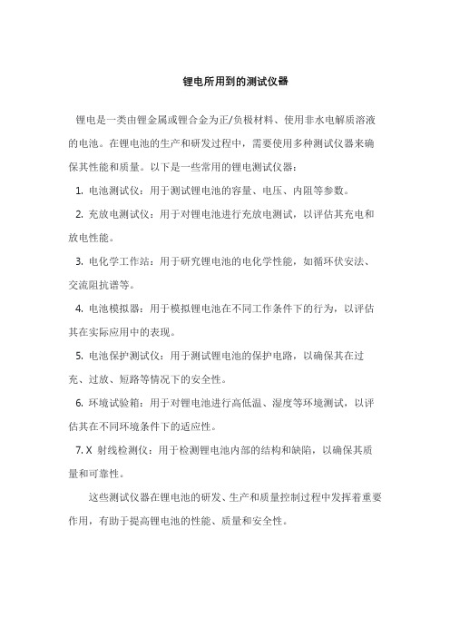
锂电所用到的测试仪器
锂电是一类由锂金属或锂合金为正/负极材料、使用非水电解质溶液的电池。
在锂电池的生产和研发过程中,需要使用多种测试仪器来确保其性能和质量。
以下是一些常用的锂电测试仪器:
1. 电池测试仪:用于测试锂电池的容量、电压、内阻等参数。
2. 充放电测试仪:用于对锂电池进行充放电测试,以评估其充电和放电性能。
3. 电化学工作站:用于研究锂电池的电化学性能,如循环伏安法、交流阻抗谱等。
4. 电池模拟器:用于模拟锂电池在不同工作条件下的行为,以评估其在实际应用中的表现。
5. 电池保护测试仪:用于测试锂电池的保护电路,以确保其在过充、过放、短路等情况下的安全性。
6. 环境试验箱:用于对锂电池进行高低温、湿度等环境测试,以评估其在不同环境条件下的适应性。
7. X 射线检测仪:用于检测锂电池内部的结构和缺陷,以确保其质量和可靠性。
这些测试仪器在锂电池的研发、生产和质量控制过程中发挥着重要作用,有助于提高锂电池的性能、质量和安全性。
电池巡检仪 电池检测仪BAT系列2.3

JP3电池接线端 JP4温度测量 JP5电流测量
电池接线顺序
备用
12 34 工作
主要功能与特性
* 24节电池电压全隔离检测,保证测量稳定;
* 配合本公司高精度电流传感器与温度传感器,可测量电池组充放电电
应用示意图
BT1BT1+ BT2+ BT3+ BT4+ BT5+ BT6+ BT7+ BT8+ BT9+ BT10+ BT11+ BT12+ BT13+ BT14+ BT15+ BT16+ BT17+ BT18+ BT19 2 1
00/2010
更多技术支持请登录本公司网站或致电公司服务热线!!!
流与两路电池环境温度;
* 2V、6V、12V电池自动分档测量,全范围量程精度保证优于0.2级;
* 模块化设计、扩展方便,可配置1~16个电池采集模块,实现1~384节电池的电压采集;
* 可监测两组独立的电池,参数独立设置;
* 电池电压采集速度快,单体采集速度达ms级,与放电模块配合可扩展内阻测试功能;
* RS485通讯接口,标准 MODBUS通讯规约;
* 安规和EMC符合CE认证
* 针对UPS系统、含逆变环节及干扰因素较多的系统作全隔离检测设计,检测
接线示意图
数据长期稳定可靠,在大量客户现场应用良好!
性能指标
功能项目参数
供电范围 功耗
- 1、下载文档前请自行甄别文档内容的完整性,平台不提供额外的编辑、内容补充、找答案等附加服务。
- 2、"仅部分预览"的文档,不可在线预览部分如存在完整性等问题,可反馈申请退款(可完整预览的文档不适用该条件!)。
- 3、如文档侵犯您的权益,请联系客服反馈,我们会尽快为您处理(人工客服工作时间:9:00-18:30)。
科研实验室电池测试系统
BT-2018A(精致四量程款)
一、技术参数5V100mA四量程
适用于:大专院校、科研机构、电池材料生产及电池生产企业对扣式电池、模拟电池、半电池、三电极电池、超级电容器等相关电化学方面的研究测试。
测试项目:充放电详细数据、循环寿命、充放电曲线、充放电效率、比容量、比能量、直流电阻、漏电(自放电)电流等项目。
二、产品外观及组合效果图
BT-2018A(精致四量程款)
三、LANB TS电池测试系统专用软件
LANB TS电池测试系统控制软件和数据分析软件借鉴了国外同类产品的优点,结合国内用户的使用习惯,我们做了全新的开发。
软件采用.NET架构,WIN10风格、平面化设计、运算速度更流畅,数据处理更强大,而且编程方案可编辑等特点。
软件启动画面
LANB TS电池测试系统监控界面
测试方案编辑界面
数据分析软件界面。