远程IO模块的使用
EPSON机器人远程io说明
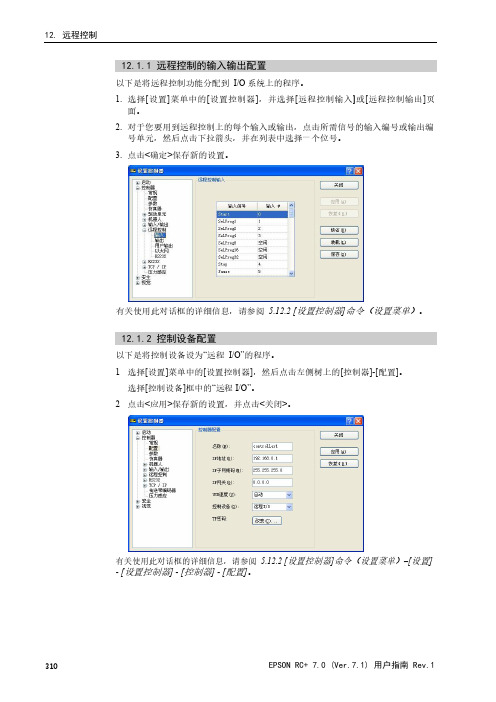
12.1.1远程控制的输入输出配置以下是将远程控制功能分配到I/O系统上的程序。
1.选择[设置]菜单中的[设置控制器],并选择[远程控制输入]或[远程控制输出]页面。
2.对于您要用到远程控制上的每个输入或输出,点击所需信号的输入编号或输出编号单元,然后点击下拉箭头,并在列表中选择一个位号。
3.点击<确定>保存新的设置。
有关使用此对话框的详细信息,请参阅 5.12.2[设置控制器]命令(设置菜单)。
12.1.2控制设备配置以下是将控制设备设为“远程I/O”的程序。
1.选择[设置]菜单中的[设置控制器],然后点击左侧树上的[控制器]-[配置]。
选择[控制设备]框中的“远程I/O”。
2.点击<应用>保存新的设置,并点击<关闭>。
有关使用此对话框的详细信息,请参阅 5.12.2[设置控制器]命令(设置菜单)–[设置] -[设置控制器]-[控制器]-[配置]。
■远程状态输出(如MotorOn,Home等)会在Teach模式ON时运行,即使在切断启用开关(控钮开关)时也是如此。
因此,不要使用远程状态输出来驱动任何设备,因其会造成动作或任何其他安全隐患。
12.1.3自动模式下使用远程控制使用远程控制以自动循环运行1.主机设备(如PLC)应在发出远程命令之前等待打开AutoMode或Ready远程输出。
2.现在,将接受远程输入命令。
从EPSON RC+7.0操作窗口中监控远程操作1.将EPSON RC+7.0启动模式设置为自动。
有关详情,请参阅4.2.3启动模式。
2.还应配置PC以自动登录到Windows中并在Windows启动过程中启动EPSONRC+7.0。
请参阅4.2.7自动启动。
12.1.4示教模式下使用远程控制在示教模式下使用远程控制时,不可以使用远程输入命令。
远程状态输出仍然会运行。
您可以使用TeachMode远程输出来监控示教模式状态。
12.1.5调试远程控制您可以使用远程控制从EPSON RC+7.0开发环境中调试程序。
R5-NE1远程I O通信模块规格书说明书

远程 I/O R5 系列通信模块机型: R5-NE1① ①在下列代码中选择。
(例如: R5-NE1/Q)・特殊规格 (例如: /C01)①附加代码◆特殊规格未填写:无特殊规格/Q:特殊规格(请从特殊规格之项另行选择)/C01: 硅涂层/C02: 聚氨酯涂层/C03: 橡胶涂层 IP地址可用组态软件进行设定。
可在本公司的网站上下载组态软件。
将本产品连接到电脑时,需要专用的连接电缆线。
所需专 用电缆线的型号请参照本公司网站的下载网站或组态软件 的使用说明书。
注)此软件的运作状况是在日文版与英文版OS上确认的。
・Ethernet: RJ-45接口・内部通信总线: 连接到底座 (机型: R5-BS) 上・内部电源: 由底座 (机型: R5-BS) 提供隔离: Ethernet-内部通信总线・内部电源间RUN显示灯: 红/绿2色LED通信正常时亮绿色灯;接收数据时亮红色灯(用DIP开关进行切换)ERR显示灯: 红/绿2色LED通信异常时绿色灯亮灯/闪烁;发送数据时,亮红色灯(用DIP开关进行切换)数据占有区设定: 用侧面的DIP开关设定占有区1或占有区2传输类型: 10BASE-T/100BASE-TX传输速度: 10/100Mbps (备有Auto Negotiation功能)通信协议: Modbus/TCP数据: RTU (二进制)通信链接数: 2个通信电缆线:・10BASE-T (STP电缆线Category 5)・100BASE-TX (STP电缆线Category 5e)最长节段: 100mIP地址: 可用组态软件 (机型: R5CON) 进行变更(初始值: 192.168.0.1)端口编号: 502Ethernet显示灯: LINK、DPLX、LINK10、LINK100、COL使用湿度范围: 30~90%RH (无冷凝)使用大气条件: 无腐蚀性气体和严重尘埃安装: 安装在底座 (机型: R5-BS) 上重量: 约100g隔离强度: Ethernet-内部通信总线・内部电源间1500V AC 1分钟电磁兼容指令(EMC指令) EMI EN 61000-6-4 EMS EN 61000-6-2RoHS指令注) 作为符合EU指令的产品使用时,要与Ver.2.00以上的电源模块 (机型: R5-PS) 一起使用。
模块控制器系列的远程I O数字模块说明书

GENERAL DESCRIPTIONThe Model CSDIO series modules are digital I/O modules designed for useSERIES DIGITAL MODULECUS LISTEDU LIND. CONT. EQ.GENERAL SPECIFICATIONS1. POWER: Derived from system backplane. (CSDIO draws 170 mA max. loadon power input of MASTER). Modules may be hot-swapped (replaced while powered up).2. LEDs:STS - Status LED shows module condition.IN1-IN8 - LEDs are lit when associated input is active.OP1-OP6 - LEDs are lit when associated output is active.ALM - Alarm LED is lit when an internal alarm condition exists.3. MEMORY: Non-volatile memory retains all programmable parameters.MASTER also stores the parameters in order to reprogram modules that are replaced.4. INPUTS: DIP switch selectable for sink or sourceMaximum voltage: +30 VDC, reverse polarity protectedOff V oltage: < 1.2 V oltsOn V oltage: > 3.8 V oltsInput Impedance: Source Mode 10K ohms; Sink Mode 20K ohmsInput Frequency*:Filter switch on: 50 HzFilter switch off: 300 Hz* Actual useable frequency limited by communication to external device.5. OUTPUTS: Outputs available as FORM-A relay or Solid State NFET.Form A Relay Output:Type: N.O.The following pairs of relays share the common terminal: 1&2, 3&4, 5&6 Current Rating by pair: 3 Amps @ 30 VDC / 125 V AC resistive1/10 HP @ 125 V ACLife Expectancy: 200,000 cycles at maximum load rating. (Decreasing load, increasing cycle time, and use of surge suppression such as RC snubbers increases life expectancy.)Solid State Output:Type: Switched DC, N Channel open drain MOSFETContact Rating: 1 ADC maxVDS ON: < 0.2 V @ 1 AVDS MAX: 30 VDCOffstate Leakage Current: 0.5 A max6. LOGIC (BOOLEAN) MODE:Count Frequency: 200 Hz/input when input is directly connected (soft-wired) to the counter.Logic Propagation Delay: 400 msecs. max.Timer Accuracy: 0.2%7. ISOLATION LEVEL: 500 Vrms @ 50/60 Hz for 1 minute between thefollowing:InputsOutputsCS Master Power Supply Input8. COMMUNICATIONS: Provided by the CS Master 9. ENVIRONMENTAL CONDITIONS:Operating Temperature Range: 0 to +50 °CStorage Temperature Range: -40 to +85 °COperating and Storage Humidity: 85% max relative humidity, non-condensing, from 0 to +50 °CVibration According to IEC 68-2-6: Operational 10 to 150 Hz, 0.075 mm amplitude in X, Y, Z direction 1 g.Shock According to IEC 68-2-27: Operational 25 g’s (10 g’s relay), 11 msec in 3 directions.Altitude: Up to 2000 meters10. CERTIFICATIONS AND COMPLIANCES:SAFETYUL Listed, File # E302106, UL508, CSA C22.2 No. 14-M05LISTED by Und. Lab. Inc. to U.S. and Canadian safety standards IEC 61010-1, EN 61010-1: Safety requirements for electrical equipment for measurement, control, and laboratory use, Part 1.ELECTROMAGNETIC COMPATIBILITYEmissions and Immunity to EN 61326: 2006: Electrical Equipment for Measurement, Control and Laboratory use.Notes:1. Criterion A: Normal operation within specified limits.2. Criterion B: Temporary loss of performance from which the unit self-recovers.3. Power supplied from back plane via Master Module.11. CONSTRUCTION: Case body is burgundy high impact plastic. For indooruse only. Installation Category II, Pollution Degree 2.12. CONNECTIONS: Removable wire clamp screw terminal blocks.Wire Gage: 28-16 AWG terminal gage wireTorque: 1.96-2.23 inch/lbs (0.22-0.25 N-m)13. MOUNTING: Snaps on to standard DIN style top hat (T) profile mountingrails according to EN50022 -35 x 7.5 and -35 x 15.14. WEIGHT: 6.6 oz (187.1 g)Electrostatic discharge EN 61000-4-2Criterion B4 kV contact discharge8 kV air discharge Electromagnetic RF fields EN 61000-4-3Criterion A10 V/mFast transients (burst)EN 61000-4-4Criterion Bpower 2 kVI/O signal2 kV1 kVSurge EN 61000-4-5Criterion Bsignalpower1 kV1 kV L-L,2 kV L-GRF conducted interference EN 61000-4-6Criterion A3 V/rmsEmissions:Emissions EN 55011Class AI/O signal connectected to powerImmunity to Industrial Locations:EMC INSTALLATION GUIDELINESAlthough Red Lion Controls Products are designed with a high degree of immunity to Electromagnetic Interference (EMI), proper installation and wiring methods must be followed to ensure compatibility in each application. The type of the electrical noise, source or coupling method into a unit may be different for various installations. Cable length, routing, and shield termination are very important and can mean the difference between a successful or troublesome installation. Listed are some EMI guidelines for a successful installation in an industrial environment.1. A unit should be mounted in a metal enclosure, which is properly connectedto protective earth.a. The mounting clip that connects to the DIN rail should have the DIN railconnected to protective earth.2. Use shielded (screened) cables for all Signal and Control inputs. The shield(screen) pigtail connection should be made as short as possible. The connection point for the shield depends somewhat upon the application.Listed below are the recommended methods of connecting the shield, in order of their effectiveness.a. Connect the shield to earth ground (protective earth) at one end where theunit is mounted.b. Connect the shield to earth ground at both ends of the cable, usually whenthe noise source frequency is over 1 MHz.c. Connect the shield to common of the module and leave the other end of theshield unconnected and insulated from earth ground.3. Never run Signal or Control cables in the same conduit or raceway with ACpower lines, conductors, feeding motors, solenoids, SCR controls, and heaters, etc. The cables should be run through metal conduit that is properly grounded. This is especially useful in applications where cable runs are long and portable two-way radios are used in close proximity or if the installation is near a commercial radio transmitter. Also, Signal or Control cables within an enclosure should be routed as far away as possible from contactors, control relays, transformers, and other noisy components.4. Long cable runs are more susceptible to EMI pickup than short cable runs.Therefore, keep cable runs as short as possible.5. In extremely high EMI environments, the use of external EMI suppressiondevices such as Ferrite Suppression Cores for signal and control cables is effective. The following EMI suppression devices (or equivalent) are recommended:Fair-Rite part number 0443167251 (RLC part number FCOR0000)TDK part number ZCAT3035-1330ASteward part number 28B2029-0A06. To protect relay contacts that control inductive loads and to minimize radiatedand conducted noise (EMI), some type of contact protection network is normally installed across the load, the contacts or both. The most effective location is across the load.a. Using a snubber, which is a resistor-capacitor (RC) network or metal oxidevaristor (MOV) across an AC inductive load is very effective at reducing EMI and increasing relay contact life.b. If a DC inductive load (such as a DC relay coil) is controlled by a transistorswitch, care must be taken not to exceed the breakdown voltage of the transistor when the load is switched. One of the most effective ways is to place a diode across the inductive load. Most RLC products with solid state outputs have internal zener diode protection. However external diode protection at the load is always a good design practice to limit EMI.Although the use of a snubber or varistor could be used.RLC part numbers: Snubber SNUB0000Varistor ILS11500 or ILS23000Note: Reference manufacturer's instructions when installing any EMI suppression device.7. Also, care should be taken when connecting input and output devices to theinstrument. When a separate input and output common is provided, they should not be mixed. Therefore a sensor common should NOT be connected to an output common. This would cause EMI on the sensitive input common, which could effect the instrument’s operation.Visit RLC’s web site at for more information on EMI guidelines, Safety and CE issues as they relate to Red Lion Controls products.WIRINGWIRING CONNECTIONSAll conductors should meet voltage and current ratings for each terminal. Also, cabling should conform to appropriate standards of good installation, local codes and regulations. When wiring the module, use the numbers on the label to identify the position number with the proper function. Strip the wire, leaving approximately 1/4" (6 mm) of bare wire exposed. Insert the wire into the terminal, and tighten.HARDWARE INSTALLATIONATTACH MODULE TO BASESEPARATE BASE FROM MODULESolid State NFET VersionRelay Version Sourcing Input Sinking InputLEDSSTS – STATUS LEDThe Status LED is a dual color LED that provides information regarding the state of the module. This includes indication of the various stages of the start-up routine (power-up), as well as any errors that may occur.Startup RoutineError States ALM – ALARM LEDThe Alarm LED indicates the presence of a fault condition. FIRMWARE UPGRADEThe module’s firmware is stored in flash memory so that software/hardware conflicts are avoided, and so that software features may be added in the future.During a download, Crimson compares its own library of firmware files with those stored in the Master module. If they do not match, Crimson will download the necessary files. The Master then checks to make sure that the I/O modules contain the same firmware. If they contain a different revision, the Master will automatically copy those files into the module's flash memory. During this process, the module LEDs will flash rapidly, starting with the top row, and progressing through the remaining rows until the process is complete. CONFIGURATIONProgramming is done via Crimson, a Windows® compatible configuration interface. Please see the Crimson manual for more information.Red Lion Controls Headquarters20 Willow Springs Circle York PA 17406Red Lion ControlsChinaUnit 101, XinAn PlazaBuilding 13, No.99 Tianzhou RoadShangHai, P.R. China 200223 Red Lion ControlsEuropePrinterweg 10NL - 3821 AD AmersfoortRed Lion ControlsIndia54, Vishvas TenementGST Road, New Ranip, Ahmedabad-382480 Gujarat, India。
RP2D系列远程IO_中文说明书20120904

RP2D系列远程I/O 用户手册版本:2.3用户手册RP2D系列远程IO 修订历史日期版本2010.04.08 1.0版本发布2011.02.10 2.0版本发布2011.02.16 2.1版本发布2012.08.21 2.2 版本修改第4页相关标准2012.09.04 2.3 版本修改错别字- 1 -RP2系列远程IO 用户手册- 2 -安全注意事项使用本产品前,请仔细阅读本手册及本手册提到的相关资料,注意正确操作产品时的安全。
本手册中给出的说明均是关于本产品的。
警告 小心 避免风险操作 谨慎操作及安装•在开始安装和接线工作之前,一定要切断整个系统外部电源。
不完全切断系统的电源能导致电击并损坏产品。
•小心不要让任何异物(如金属碎箔和接线碎片)进入模块内部,这些异物可能导致火灾或故障。
•必须将连接模块的通讯电缆和电源电缆敷设在电缆槽中或者用夹子固定。
•在符合模块手册中规定的一般操作环境下使用。
在不符合本手册中规定的一般操作环境规格下使用时,可能会引起电击、火灾、故障,并会损坏产品,或使产品不能达到预期效果。
• 正确安装模块,如果模块安装得不正确,可能导致模块故障、失效或跌落。
• 在安装或拆卸模块之前,一定要断开外部电源,否则可能损坏产品。
• 不要直接触摸模块的导电部分和电子部件,可能会导致模块故障或失效。
• 在安装或拆卸模块之前,必须先切断外部电源。
否则可能导致模块受损或故障。
• 通电时不要触摸端子。
可能会导致模块损坏或故障。
• 在清洁模块或重新紧固端子螺钉和模块固定螺钉之前,必须先切断外部电源。
非专业人士勿操作用户手册RP2D系列远程IO`目录1.简介 ..................................................................................................................................- 4 -1.1. CANopen 远程IO概述.....................................................................................- 4 -1.2. 产品应符合的标准和规范 ..................................................................................- 4 -1.3. 产品类别区分 ......................................................................................................- 4 -1.4. Kinco RP2D系列远程IO产品列表..................................................................- 5 -2. 技术特点 ..........................................................................................................................- 6 -2.1. CANopen特点 ....................................................................................................- 6 -2.2. 通信和设备配置 ..................................................................................................- 6 -2.3. 电源, 环境条件和外壳 ......................................................................................- 6 -3.CAN总线模块连接设置.........................................................................................- 7 -3.1. 节点ID设置 ........................................................................................................- 7 -3.2. 波特率 ..................................................................................................................- 7 -3.3. 终端电阻 ..............................................................................................................- 8 -3.4. CAN总线连接 .......................................................................................................- 8 -3.5. 数据服务对象(SDO) ..........................................................................................- 9 -3.6. 过程数据对象(PDO) ........................................................................................ - 11 -3.7. NMT 模块控制 .................................................................................................- 12 -3.8. NMT节点保护 ..................................................................................................- 12 -3.9. Emergency - 紧急对象 .....................................................................................- 14 -4.LED指示灯说明....................................................................................................- 15 -5.数字IO模块 ..........................................................................................................- 18 -5.1. RP2D-1608C1, 16DI + 8DO DC 24V ................................................................- 18 -5.2. RP2D-0016C1, 16DO DC 24V ..........................................................................- 22 -6. 安装尺寸 ........................................................................................................................- 25 -- 3 -RP2系列远程IO 用户手册- 4 -1. 简介1.1. CANopen 远程 IO 概述远程I/O 是一种提供现场总线接口的I/O 系统,由各种扩展模块和各种总线接口模块组成。
DELTA RTU-DNET DeviceNet 远程 IO 通讯模块 应用技术手册

RTU-DNETDeviceNet 远程IO通讯模块应用技术手册DVP-0214110-02DeviceNet 远程IO 通讯模块 RTU-DNETDVP-PLC应用技术手册 i注意事项3 此应用技术手册提供功能规格、安装、基本操作与设定,以及有关于网络协议内容的介绍。
3 本机为开放型 (OPEN TYPE) 机壳,因此使用者使用本机时,必须将之安装于具防尘、防潮及免于电击/冲击意外之外壳配线箱内。
另必须具备保护措施 (如:特殊之工具或钥匙才可打开) ,防止非维护人员操作或意外冲击本体,造成危险及损坏,且请勿在上电时触摸任何端子。
3 请务必仔细阅读本使用手册,并依照本手册指示进行操作,以免造成产品受损,或导致人员受伤。
目录1 产品简介 (1)1.1产品特点..........................................................................................................................................................1 1.2功能规格..........................................................................................................................................................1 1.3支持的扩展模块 (2)1.4 支持的MODBUS 设备 (3)2 RTU-DNET 单元部件 (4)2.1外观尺寸..........................................................................................................................................................4 2.2各部介绍..........................................................................................................................................................4 2.3DeviceNet 通讯连接器....................................................................................................................................4 2.4RUN/STOP 开关..............................................................................................................................................5 2.5地址设定开关...................................................................................................................................................5 2.6RS485通讯端口..............................................................................................................................................5 2.7功能设定开关 (5)2.8 扩展IO 界面 (6)3 RTU-DNET 安装 (7)3.1 安装RTU-DNET 与Slim 扩展模块 (7)3.2 安装RTU-DNET 及其Slim 扩展模块于导轨 (7)3.3 连接DeviceNet 通讯连接器 (7)4 配置RTU-DNET (8)4.1 术语解释 (8)4.2 软件介绍 (9)4.2.1 RTU 配置主接口 (9)4.2.2 RTU 设定接口 (10)4.2.3 特殊模块配置接口 (11)4.2.4 网关设置界面 (12)4.3 DeviceNet IO 映像数据 (12)4.3.1 RTU-DNET 控制字和状态字 (12)4.3.2 IO 数据映像 (14)5 应用范例 (17)5.1 使用RTU-DNET 组成DeviceNet 网络 (17)5.2 使用DeviceNet 配置工具配置网络 (18)5.3 使用梯形图控制整个网络 (26)6 扩展波特率设置方法 (28)7 错误诊断及故障排除 (31)DeviceNet 远程IO 通讯模块 RTU-DNETDVP-PLC 应用技术手册ii 7.1 指示灯诊断 (31)7.2 状态字诊断 (32)7.3 软件诊断 (33)附录A RTU-DNET 支持的标准DeviceNet 对象 (34)附录B RTU-DNET 自定义的DeviceNet 对象 (38)DeviceNet 远程IO通讯模块 RTU-DNET1 产品简介1. 感谢您使用台达RTU-DNET模块。
昆山兴威联电气有限公司PNL16远程IO模块安装使用说明书

PNL16远程IO模块安装使用说明书手册简介本手册适用于昆山兴威联电气有限公司所生产的PNL16远程I0模块本手册主要介绍了PNL16远程I0模块的硬件特性、安装方法、主要功能及配置过程阅读对象本手册适合下列人员阅读电气工程师现场装配人员相关约定本手册采用了如下几种醒目标志来表示操作过程中应该注意的地方,这些标志的意义如下:该图标表示需引起重视的警告事项。
该图标表示提醒操作中应注意的事项,如果操作错误可能导致设备损坏等不良后果。
该图标表示对操作内容的描述进行必要的补充和说明。
版权声明昆山兴威联电气有限公司版权所有,并保留对本手册及本声明的最终解释权和修改权。
本手册的版权归昆山兴威联电气有限公司所有。
未得到昆山兴威联电气有限公司的书面许可,任何人不得以任何方式或形式对本手册内的任何部分进行复制、摘录、备份、修改、传播、翻译成其它语言、将其全部或部分用于商业用途。
免责声明本手册依据现有信息制作,其内容如有更改,恕不另行通知。
昆山兴威联电气有限公司在编写该手册的时候已尽最大努力保证其内容准确可靠,但昆山兴威联电气有限公司不对本手册中的遗漏、不准确或印刷错误导致的损失和损害承担责任。
商标声明为昆山兴威联电气有限公司注册商标。
本手册提及的所有商标,由各自所有人拥有。
发行版本:V2.0第一章:产品介绍1.1 产品简介PNL16系列远程IO模块是昆山兴威联电气有限公司自主研发符合Profinet V2.3通讯协议的16通道工业数字输入输出模块。
本系列产品采用M12 T Code编码连接器供电,与传统的7/8"连接器相比,不但可以提供更大的电流(12A),更是可以节约宝贵的现场安装空间。
1.2 外观及安装尺寸1.3 端口介绍1.3.1 网络及电源针脚定义C0/C2/C4/C6C1/C3/C5/C7脚位 ETH(以太网)PWR(电源)1TD+(黄,与RJ45 1脚连接) 24V( US+ ) 2 RD+(白,与RJ45 3脚连接) GND( UA- ) 3 TD-(橙,与RJ45 2脚连接) GND( US- ) 4RD-(蓝,与RJ45 6脚连接)24V( UA+ )1.3.2 I/O 信号A 编码母头针脚定义 PIN 位说明1 24V ( PN16DO未使用)2 PIN 2信号3 GND4 PIN 4信号5FEC0C2C4C61.4 指示灯说明1.4.1 以太网及电源指示灯1.4.2 I/O 信号指示灯指示灯 颜色 含义 状态 说明2 绿色 对应端口PIN 2信号 绿色 端口PIN 2有信号 熄灭 端口PIN 2无信号 4绿色对应端口PIN4信号绿色 端口PIN 4有信号 熄灭端口PIN 4无信号第二章:安装说明2.1 相关配件订购I/O 接口M12 A 编码公头螺钉接线圆形连接器 912701PWR INM12 T 编码公头螺钉接线圆形连接器 912744PWR OUTM12 T 编码母头螺钉接线圆形连接器 912932ETH 接口M12 D 编码公头螺钉接线圆形连接器 914521I/O 接口M12 Y 型分支器 941121PWR INM12 T 编码母头预制线缆屏蔽、固定安装:913344-902-xxxx 屏蔽、拖链抗扭:913344-901-xxxx 非屏蔽、固定安装:912344-960-xxxxPWRM12 T 编码公母对接预制线缆屏蔽、固定安装:943044-902-xxxx 屏蔽、拖链抗扭:943044-901-xxxx 非屏蔽、固定安装:942044-960-xxxxETHM12 D 编码公公对接预制线缆固定安装:944511-790-xxxx 拖链抗扭:944511-796-xxxxM12母端口保护盖996050标识片2 plates = 10 pieces999006更多配件请访问我们的网站 或者联系我们的业务人员2.2 连接说明2.2.1 设备接地为避免数据损坏或丢失,请确保设备接地良好2.2.2 网线屏蔽为避免网络数据损坏或者丢失,请使用专用的Profinet网线,并保证网线的屏蔽层接地良好。
WG1830使用手册(CANopen总线远程IO模块)

WG1830使用手册(CANopen总线远程IO模块)WG1830系列CANopen远程IO模块使用手册DOC. WG1830. 2012-8-13目录1 前言 (3)2 产品概述 (4)2.1 系统介绍 (4)2.2 产品各部介绍 (5)2.3 产品规格 (5)2.4 产品安装 (6)2.5 安装尺寸 (7)3 硬件设置 (8)3.1 电源接口 (8)3.2 CANopen接口 (8)3.2.1 CANopen接口特性 (8)3.2.2 网络原理 (9)3.2.3 线缆的选择 (9)3.2.4 布线注意事项 (10)3.2.5 接线方法 (11)3.3 CANopen地址设置开关 (11)3.4 CANopen通讯速率设置开关 (12)3.5 输入输出规格 (13)3.5.1 端子排列 (13)3.5.2 输入规格 (14)3.5.3 输出规格 (15)4 故障诊断 (18)5 CANopen功能 (20)5.1 通讯功能 (20)5.2 支持的服务 (20)5.3.1 PDO (实时数据交换服务) (20)5.3.2 SDO(参数读写服务) (22)5.3.3 NMT(网络管理服务) (23)6 CANopen 对象字典 (25)6.1 通讯对象 (25)6.2 厂商定义对象 (26)6.3 数字输入量对象 (28)6.3.1 输入量对象 (28)6.3.2 触发事件 (29)6.3.3 输入逻辑 (30)6.4 数字输出量对象 (32)6.4.1 输出量对象 (32)6.4.2 输出逻辑 (33)1前言感谢选用ENJOY提供的WG18XX系列工业现场总线远程IO模块,本系列模块具有多种现场总线通讯功能,内置数字量、模拟量,及一些特殊输入输出功能,如脉冲输入输出,温度检测等功能。
现场总线类型包括Profibus-DP , DeviceNet ,CANopen等较流行的总线系统。
使用WG18XX远程IO模块,可以快速、简便的将远程IO连接到现场总线系统中,进行实时监控和控制。
远程I O适配器模块说明书

Local Fault Adapter Fault Adapter Active Power ON/OFF
AllenĆBradley ADAPTELROCAL PWRACTIVE FAULTFAULT
Reset Switch
Troubleshooting with the Indicator Lights
within the last 255 link transactions • communication is lost to a module when Rack Fault Select is
enabled When any of these conditions exist, the adapter will:
The module has indicators on the front plate as shown below. Use these indicators for troubleshooting the module. The following tables describes problems that may occur, probable causes, and recommended courses of action.
during communications by setting.
scanner
No replies sent to scanner
Press Reset button on front of adapter module (or cycle power) and resume proper communication.
ADAPTERLOCAL PWR ACTIVE FAULT FAULT
Local Fault Off Off
- 1、下载文档前请自行甄别文档内容的完整性,平台不提供额外的编辑、内容补充、找答案等附加服务。
- 2、"仅部分预览"的文档,不可在线预览部分如存在完整性等问题,可反馈申请退款(可完整预览的文档不适用该条件!)。
- 3、如文档侵犯您的权益,请联系客服反馈,我们会尽快为您处理(人工客服工作时间:9:00-18:30)。
远程IO模块的使用
一产品简介
1.从控制方面来看,远程IO模块主要分485总线控制,以太网控制,WiFi控制和p2p功能远程监控
2.从设备路数来看,远程IO模块主要分4路和8路,分别是AI(模拟量采集),DI(数字量采集),DO(继电器控制)
二软件使用
Remote IO 软件搜索设备,配置设备的地址等高级参数,检测DO DI的状态ZLvircom软件主要配置网络型远程IO模块的网络参数
1.串口485总线控制类型
找到相对应的485转usb接电脑的映射串口
如果为ZLAN6002型号,RJ45将变为RS485信号,485的A、B线分别对应RJ45座的1,2线。
如果为ZLAN6802型号,串口就是485接口,485的A、B线分别对应485的正、负。
进入配置模式,首先打开相应的串口,点击搜索设备。
搜到设备之后报告区域会显示。
继电器状态显示区是显示DO当前的状态,控制DO的开和关,继电器状态显示器会实时变化。
例:RL1开设备会响一声同时6802的DO1灯会亮,表示常开状态
点击查询DI状态会显示当前DI的状态,DI状态变化显示区不会实时更新,只有客户点击才会更新,打钩表示该路DI由低电平输入,此时输入DI灯亮
点击查询AI状态会显示当前的AI的模拟量,对于6802默认前4路采集电压,后4路采集电流,对于6002默认2路采集电压。
2.网络控制类型
进入参数配置时,RemoteIO中转化协议和远程IO配置的转化协议保持一致,串口参数固定115200、8、无、1、无,在下图中转化协议和串口参数不能显示错误,如果显示错误,可以通过Vircom软件修改。
3.高级参数的介绍
固件版本:表示远程IO软件的版本
设备地址:表示远程IO的地址,可以修改
波特率:表示远程IO485接口的波特率
启用DI主动上报:当选择为1时,DI主动上报,0不上报
DI上报地址:这个功能是实现DI控制DO的,当启用DI主动上报之后,DI会控制相应的DO。
(主要应用:两个设备对联,实现DI控制DO)
AI主动上报:AI会按照周期往上位机发送
4.指令集的使用
Remote IO软件只能简单的测试DI DO的状态,并不能确切地测试出AI的实际数据,如果需要查询AI的详细数值可以通过客户自己的上位机软件或者发送指令查询,下面简单描述指令查询的操作。
1.网口调试工具连上我们网络型IO控制设备
2.发送指令集查询
上述指令是查询AI的状态,接收区可查看每路AI的数值,具体解析可参考指令集
四常见问题
1.发送指令成功,但是没有返回,检查modebus指令报文是否正确,报文格式,CRC效验等
2.搜索不到设备,串口号是否正确,是否同一局域网
3.连不上设备,TCP未建立,检查是否同一局域网,参数配置是否一致。