动态矩阵和模型预测控制的半自动驾驶汽车(自动控制论文)
基于模型预测控制的控制系统设计
基于模型预测控制的控制系统设计随着现代控制技术的不断发展,控制系统的设计已经逐步演化为了一种高度智能化的过程。
在此过程中,基于模型预测控制(MPC)的设计方案已经成为了一个备受重视的研究领域。
MPC是一种基于最优控制理论的控制策略,它能够优化系统动态性能,使得系统在保证控制精度的同时,也能够对外部环境的变化作出相应的响应。
本文将从MPC的概念和优点入手,探讨基于MPC的控制系统设计的实现方式和应用场景。
一、MPC的概念和优点MPC是一种优化控制策略,它基于模型的预测结果来对系统进行控制。
MPC可以将目标系统视为一个黑盒子,通过建立对其动态响应特性的数学模型来实现理论分析和仿真,然后根据模型预测结果计算出最优控制策略。
这种控制方式具备以下4个优点:1. 对外部干扰较为鲁棒。
MPC对外部环境变化的响应速度较快,可以有效抑制外部干扰的影响。
2. 对自身参数变化具有适应性。
MPC通过建立模型,可以快速地适应自身的参数变化,实现对控制精度的优化。
3. 对非线性系统控制有很好的效果。
MPC的优化控制算法可以应用于非线性系统的控制中,实现对系统非线性响应的有效控制。
4. 动态性能优于传统的控制策略。
MPC具有更好的控制精度、更快的响应速度和更小的超调量,使得系统具有更好的动态性能。
二、基于MPC的控制系统设计实现方式MPC的控制系统实现方式包括以下三个步骤:1. 建立系统数学模型。
在实际控制过程中,建立系统的数学模型是首要任务。
该模型应包括系统的状态空间描述、控制对象的特性和控制目标等参数。
2. 模型预测控制计算。
通过对系统数学模型进行仿真计算,预测出当前状态下的控制策略。
3. 实际操作控制。
将计算得到的控制策略反馈给系统,实现对控制效果的实际控制。
基于MPC的控制系统设计实现方式既可以完成离线实验,也可以进行在线实时控制。
其中,离线实验通过模拟系统实现对控制策略的仿真计算;在线实时控制则可以在现场对控制策略进行计算和实时控制。
无人驾驶汽车论文【范本模板】
无人驾驶汽车院别:**学院专业:自动化学号:******** 姓名:*********摘要:无人驾驶汽车通过传感器装置和计算机来实现无人驾驶,这一技术正渐渐地在生活中的到应用,并在生活中发挥着巨大的作用,有着广泛的发展前景.2009年11月,在国外某社交网站上的一段视频,引起广泛关注。
视频的上传者本·蔡特林在美国旧金山和帕洛阿尔托之间的280号高速公路行驶时,发现旁边有一辆“怪异"的丰田普锐斯轿车,在它的车顶,装着一个类似于扰流板的装置,蔡特林最初以为这是用来测试风速的,其实这就是谷歌所研发的无人驾驶汽车系统,在当时,这还是一个秘密进行中的项目。
关键字:无人驾驶汽车,智能,传感器,导航,安全一、无人驾驶汽车概念什么是无人驾驶汽车?清华大学汽车系副研究员王建强将无人驾驶汽车定义为“通过车载传感系统感知道路环境,自动规划行车路线并控制车辆到达预定目标的智能汽车”。
同时它也可以称之为轮式移动机器人,其核心在于位于其内的计算机系统。
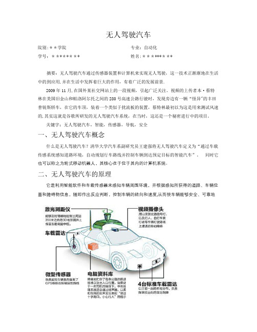
二、无人驾驶汽车的原理它是利用智能软件和车载传感器来感知车辆周围环境,并根据感知所获得的道路、车辆位置和障碍物信息,随即作出反应判断,控制车辆的转向和速度,从而使车辆能够安全、可靠地在道路上行驶。
比如,车体多个部位装有激光感应器,用于确定车身与障碍物的距离;有效地避开障碍物。
车载电脑可以经由后视镜附近的摄像头识别交通信号、交通标志并分析路况。
无人驾驶车的运动控制包括感知、动作、行为3个部分。
感知主要是通过车的“眼睛”认知周围环境,实现对环境的精确建模,如结构化环境中的车道线的检测、半结构环境中的边缘检测等;动作是指车的“大脑”在收到感知信息时作出的规划、控制与决策;而行为则是无人驾驶汽车在规划、控制与决策下产生的外在响应,体现了无人车的自主性能。
无人驾驶车是集视觉计算、模式识别和控制等众多技术于一体、具有人工智能功能的汽车。
它有车载麦克风、声波定位仪、红外线传感器、罗盘、激光扫描仪和微波雷达等多种传感器,这些装置相当于无人驾驶车辆的“眼耳”,用来感知车辆周围环境,并将感知所获得的道路、车辆位置、障碍物信息等,传输给无人驾驶车辆的“大脑”-—安装在车辆内部的高性能计算机进行分析和计算,以控制车辆的转向和速度,从而使车辆在遵守交通规则的前提下能够安全、可靠地在道路上自主行驶.当然,不同公司生产的无人驾驶汽车其原理都不太一样。
《2024年动态场景下基于交互性预测的自动驾驶汽车轨迹规划方法研究》范文
《动态场景下基于交互性预测的自动驾驶汽车轨迹规划方法研究》篇一一、引言随着自动驾驶技术的飞速发展,自动驾驶汽车在动态场景下的轨迹规划已成为当前研究的热点问题。
该问题的核心在于如何有效地处理动态场景中的复杂交通状况,如其他车辆、行人等的行为预测和实时交互性,以确保自动驾驶汽车在复杂道路环境下安全、高效地行驶。
本文将就动态场景下基于交互性预测的自动驾驶汽车轨迹规划方法进行深入研究。
二、研究背景及意义自动驾驶汽车技术的发展,旨在提高道路交通的安全性、减少交通拥堵和提高出行效率。
然而,在动态场景下,自动驾驶汽车需要实时感知周围环境,预测其他交通参与者的行为,并据此进行轨迹规划。
因此,基于交互性预测的轨迹规划方法成为自动驾驶技术研究的重点和难点。
三、相关文献综述目前,国内外学者在自动驾驶汽车轨迹规划方面进行了大量研究。
其中,基于预测模型的方法、基于优化算法的方法和基于学习的方法是主要的三种研究方法。
然而,这些方法在处理动态场景下的交互性预测时仍存在一定局限性。
因此,本文将重点研究基于交互性预测的自动驾驶汽车轨迹规划方法。
四、动态场景下基于交互性预测的轨迹规划方法(一)交互性预测模型本文提出一种基于多模态深度学习网络的交互性预测模型。
该模型通过融合多种传感器数据(如雷达、摄像头等),实时感知周围环境,预测其他交通参与者的行为。
此外,模型还考虑了不同交通场景下的复杂性和不确定性,提高了预测的准确性和可靠性。
(二)轨迹规划算法在获得其他交通参与者的行为预测后,本文采用一种基于优化算法的轨迹规划方法。
该方法通过设定一系列约束条件(如安全性、舒适性等),寻找最优的轨迹规划方案。
同时,为了应对动态场景下的实时变化,该方法还采用了滚动时域优化策略,实现了实时在线的轨迹规划。
五、实验与分析为了验证本文提出的基于交互性预测的轨迹规划方法的性能,我们在多种复杂道路环境下进行了实车测试和仿真实验。
实验结果表明,该方法在处理动态场景下的交互性预测和轨迹规划问题时,具有较高的准确性和鲁棒性。
基于动态矩阵控制的机车车辆半主动悬挂控制设计
第 2卷 年 月 l1 第4 2 0 4 期 0
鼹 钸
V1 o o1 N. . 4 2
Ap . 2 0 r 01
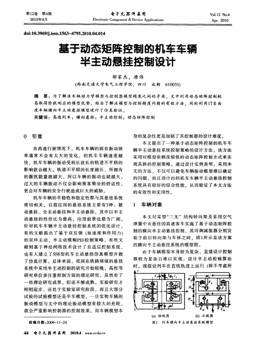
在 外 轨 道 的 曲率 半 径 和 外 轨 超 高 ) ,同 时 略 去 旋 转 蠕滑 率等 微 小 因素 的影 响 ,由此得 到 的 1 自由 7
度 车辆横 向悬 挂模 型 的输 入输 出参 数如 表 1 所列 。
一
的横 向半 主动 悬挂 系统 的模 型图 。 由于车 辆模 型本 身较 为复 杂 ,直 接设 计控 制 器 较 为 复 杂 且 难 以实 现 。设 计 半 主 动 控 制 算 法 时 ,现 假设 列 车在 直 线轨 道 上 运行 ( 即不 考虑 所
L
IK r ’
H 1 —
第 l卷 2
第4 期
电手元 嚣 件 盔 用
Elc r i mpo e t& De ieAp i ai s e tonc Co nn vc plc ton
Vo .2 N . I o4 1
Apr .201 0
2 1年 4 00 月
d i O3 6 / i n1 6 - 7 52 1 .40 4 o: .9 9j s .5 3 4 9 . 00 .1 l .s 0
针对 机 车 车 辆 半 主动 悬 挂 控 制 系统 的优 化设 计 。
身 的复杂 性更是 加剧 了其 控制器 的设 计难 度 。 本 文 提 出 了一 种基 于 动态矩 阵控 制 的机车 车
辆半 主 动悬挂 系 统控 制策 略 的设 计 方法 。该 方 法 采用 对模 型依 赖 度较低 的动态 矩阵 控制 方式 来 实
( a 视图 )俯
收稿 日期 :0 9 1 - 4 2 0 — 1 2
《2024年基于多模型预测控制的列车自动驾驶系统研究》范文
《基于多模型预测控制的列车自动驾驶系统研究》篇一一、引言随着城市交通的日益繁忙和复杂化,列车自动驾驶系统(Automatic Train Operation,简称ATO)的研究与应用显得尤为重要。
多模型预测控制(Multi-model Predictive Control,简称MPC)作为一种先进的控制策略,在列车自动驾驶系统中得到了广泛的应用。
本文旨在研究基于多模型预测控制的列车自动驾驶系统,以提高列车的运行效率、安全性和舒适性。
二、多模型预测控制概述多模型预测控制是一种基于模型的预测控制方法,它通过建立多个模型来描述系统的不同运行状态,并根据当前的系统状态选择最合适的模型进行预测和控制。
在列车自动驾驶系统中,多模型预测控制可以根据列车的运行环境、速度、加速度等参数,建立多个模型,以实现对列车的精确控制和优化。
三、基于多模型预测控制的列车自动驾驶系统研究1. 系统架构设计基于多模型预测控制的列车自动驾驶系统主要由传感器、控制器、执行器等部分组成。
传感器负责采集列车的运行状态和环境信息,控制器根据采集的信息选择最合适的模型进行预测和控制,执行器则根据控制器的指令驱动列车进行运行。
2. 模型建立与优化在列车自动驾驶系统中,模型的准确性和可靠性对于系统的性能至关重要。
因此,需要建立多个模型来描述列车的不同运行状态。
这些模型可以通过历史数据、仿真实验等方式进行训练和优化,以提高模型的准确性和可靠性。
同时,还需要考虑模型的复杂度和计算量,以保证系统的实时性和响应速度。
3. 控制器设计控制器是列车自动驾驶系统的核心部分,它需要根据传感器采集的信息选择最合适的模型进行预测和控制。
因此,需要设计一种有效的控制器,以实现对列车的精确控制和优化。
在多模型预测控制中,可以采用基于规则的控制器、基于优化的控制器等方法进行设计。
4. 实验与验证为了验证基于多模型预测控制的列车自动驾驶系统的性能,需要进行实验和验证。
可以通过仿真实验和实际运行实验等方式,对系统的准确性、稳定性和响应速度等进行评估。
人工智能在自动驾驶汽车中的关键技术
人工智能在自动驾驶汽车中的关键技术自动驾驶汽车作为近年来备受关注和期待的技术创新,正逐渐改变着我们对交通出行的认识。
其背后的支持和推动力之一,便是人工智能技术的应用。
人工智能在自动驾驶汽车中扮演着关键的角色,其涵盖的技术范畴十分广泛,其中包括感知、决策和控制等多个方面。
本文将重点探讨人工智能在自动驾驶汽车中的关键技术,并窥探其未来发展趋势。
首先,感知是自动驾驶汽车中的核心技术之一。
感知技术旨在通过传感器获取周围环境的信息,为自动驾驶系统提供准确的视觉、声音和其他感知输入。
在感知技术的发展中,深度学习是一项重要的工具。
借助深度学习算法,自动驾驶汽车可以对传感器获得的大量数据进行高效处理和分析,从而实现对交通标志、车道线、行人和其他车辆等信息的准确识别和感知。
此外,激光雷达、毫米波雷达和摄像头等传感器的不断演进也为感知技术的发展提供了有力支持。
其次,决策是自动驾驶汽车的另一个重要技术环节。
决策技术主要涉及自动驾驶系统对行驶环境的理解和作出相应决策的能力。
在决策技术中,路径规划和交通预测是具有重要影响力的研究方向。
路径规划旨在为自动驾驶汽车提供最佳行驶路线,并在遇到障碍物和限制条件时进行及时调整。
交通预测则是通过分析和预测其他车辆、行人和其他路上元素的行为,以帮助自动驾驶系统做出适当决策,例如加速、减速、转向等。
在决策技术中,强化学习和深度强化学习等算法的应用也日益成为研究的热点,这些算法能够从大量的数据中学习并逐步优化决策过程。
最后,控制是实现自动驾驶汽车的关键技术之一。
控制技术旨在确保自动驾驶系统能够准确、稳定地执行决策。
在控制技术中,模型预测控制和非线性控制等方法被广泛应用。
模型预测控制通过建立车辆运动模型和环境模型,预测未来一段时间内的车辆和环境状态,并通过优化算法生成控制指令。
非线性控制则主要关注车辆在动态环境下的稳定性和精确性,通过对车辆动力学建模和控制器设计来实现最佳控制效果。
此外,实时控制也是自动驾驶汽车的一个挑战,需要保证控制指令的实时执行,以应对场景的变化和处理紧急情况。
自动驾驶汽车动力学模型及控制策略研究
自动驾驶汽车动力学模型及控制策略研究一、引言随着人工智能与数字技术的飞速发展,自动驾驶汽车已经从科幻电影进入现实生活,并成为了未来交通运输领域的主角之一。
尽管目前大多数自动驾驶汽车还处于实验室和测试阶段,但是其持续的发展和创新已经让人们看到了自动驾驶汽车在未来交通运输中的无限可能性。
本文就自动驾驶汽车的动力学模型及控制策略做一些探讨。
二、自动驾驶汽车动力学模型自动驾驶汽车动力学模型是指汽车在不同速度下的动态行驶特性及其动态模型。
在自动驾驶汽车中,动力学模型是其系统技术的核心特征,因为它直接影响到车辆的运动状态和行驶安全。
1. 系统构成自动驾驶汽车动力学模型包括控制系统、传感系统、执行系统和运动轮。
2. 状态方程状态方程可以描述汽车在空间中的位置和速度等状态量的变化过程,其一般表示为:$$\dot{x}=f(x,u,v,t,k)$$其中,$x$是状态量,$u$是控制输入,$v$是扰动输入,$t$是时间变量,$k$是汽车的固有参数。
状态方程中的$f$函数是动力学模型的数学函数。
3. 动力学控制动力学控制是指使用动力学模型对自动驾驶汽车的运动状态进行表示,并对其运动状态进行控制的一种控制方式。
传统的PID 控制方式过于简单粗糙,因此需要使用更加精细的动力学控制方法。
动力学控制可以提高汽车的行驶安全性和减少能量浪费。
三、自动驾驶汽车控制策略在自动驾驶汽车中,控制策略是指驱动自动驾驶汽车的核心策略,包括路径规划、速度控制等多个方面。
1. 路径规划路径规划是指从某一个起点到达目标点的路径规划,其包括全局路径规划和局部路径规划。
全局路径规划是在整个地图中寻找最短路径,而局部路径规划是在已经找到的路径上进行微调,以确保汽车的安全行驶。
2. 速度控制速度控制是指自动驾驶汽车行驶速度的控制策略,主要是通过调整电机负载、调节驱动电机的旋转速度等技术手段,使自动驾驶汽车的速度得到有效控制。
3. 停车控制停车控制是指自动驾驶汽车停车的控制策略,包括泊车、平行停车、倒车入库等多种技术方式。
控制理论在汽车自动驾驶中的应用研究
控制理论在汽车自动驾驶中的应用研究自动驾驶技术是近年来汽车行业中快速发展的一个领域,它的实现离不开控制理论的应用。
控制理论通过建立数学模型和设计控制算法,可以对汽车进行精确的控制,以实现安全、高效的自动驾驶。
本文将探讨控制理论在汽车自动驾驶中的应用研究。
首先,控制理论在自动驾驶中的应用主要体现在车辆操控和路径规划上。
针对车辆操控,控制理论可以通过传感器获取车辆的状态信息,如速度、加速度、转角等。
然后,通过设计控制算法,对车辆进行实时调整以保证行驶的稳定性和安全性。
控制理论对车辆操控的研究包括PID控制器、模型预测控制、自适应控制等,通过不断优化调整参数,可以使车辆在自动驾驶过程中更稳定地运行。
其次,路径规划是自动驾驶中的重要环节,也是控制理论的应用之一。
自动驾驶汽车需要通过传感器获得道路、交通标志和其他车辆等信息,并根据这些信息确定最优路径。
控制理论中的最优控制理论和优化算法可以根据不同的目标函数,快速计算出最佳路径,如最短路径、最小时间、最小能耗等。
通过控制理论的应用,能够使自动驾驶汽车更加高效地行驶,提高行驶的安全性和节能性。
另外,控制理论还可以应用于自动驾驶汽车的感知与决策过程。
感知环节可以通过传感器获取道路、交通标志、行人等环境信息,并进行数据融合和目标识别。
控制理论中的滤波算法、模式识别等技术可以对感知到的信息进行处理和识别,提高环境感知的准确性。
在决策环节,控制理论可以通过建立驾驶策略和规划行为来实现智能决策。
例如,通过强化学习算法和最优控制理论,可以使自动驾驶汽车具备警戒、避障和规避等智能决策能力,从而提高行驶的安全性。
此外,控制理论在自动驾驶中的应用还可以进一步与人工智能技术相结合。
人工智能的深度学习算法可以通过大量的数据训练出更高效、准确的控制模型。
通过将深度学习应用于控制理论中,可以提高自动驾驶汽车的环境感知和决策能力。
同时,控制理论也可以用于优化人工智能模型的参数,使其更好地适应自动驾驶的需求。
- 1、下载文档前请自行甄别文档内容的完整性,平台不提供额外的编辑、内容补充、找答案等附加服务。
- 2、"仅部分预览"的文档,不可在线预览部分如存在完整性等问题,可反馈申请退款(可完整预览的文档不适用该条件!)。
- 3、如文档侵犯您的权益,请联系客服反馈,我们会尽快为您处理(人工客服工作时间:9:00-18:30)。
Dhaval Shroff1, Harsh Nangalia1, Akash Metawala1, Mayur Parulekar1, Viraj Padte1Research and Innovation CenterDwarkadas J. Sanghvi College of EngineeringMumbai, India.dhaval92shroff@; mvparulekar@Abstract—Dynamic matrix and model predictive control in a car aims at vehicle localization in order to avoid collisions by providing computational control for driver assistance whichprevents car crashes by taking control of the car away from the driver on incidences of driver’s negligence or distraction. This paper provides ways in which the vehicle’s position with reference to the surrounding objects and the vehicle’s dynamic movement parameters are synchronized and stored in dynamic matrices with samples at regular instants and hence predict the behavior of the car’s surrounding to provide the drivers and the passengers with a driving experience that eliminates any reflex braking or steering reactions and tedious driving in traffic conditions or at junctions.It aims at taking corrective action based on the feedback available from the closed loop system which is recursively accessed by the central controller of the car and it controls the propulsion and steeringand provides a greater restoring force to move the vehicle to a safer region.Our work is towards the development of an application for the DSRC framework (Dedicated Short Range Communication for Inter-Vehicular Communication) by US Department of Traffic (DoT) and DARPA (Defense Advanced Research Projects Agency) and European Commission- funded Project SAVE-U (Sensors and System Architecture for Vulnerable road Users Protection) and is a step towards Intelligent Transportation Systems such as Autonomous Unmanned Ground and Aerial Vehicular systems.Keywords-Driver assist, Model predictive control, Multi-vehicleco-operation, Dynamic matrix control, Self-mappingI.INTRODUCTIONDriver assist technologies aim at reducing the driver stress and fatigue, enhance his/her vigilance, and perception of the environment around the vehicle. It compensates for the driver’s ability to react [6].In this paper, we present experimental results obtained in the process of developing a consumer car based on the initiative of US DoT for the need for safe vehicular movement to reduce fatalities due to accidents [5]. We aim at developing computational assist for the car using the surrounding map data obtained by the LiDAR (Light Detection and Ranging) sensors which is evaluated and specific commands are issued to the vehicle’s propellers to avoid static and dynamic obstacles. This is also an initiative by the Volvo car company [1] where they plan to drive some of these control systems in their cars and trucks by 2020 and by General Motors, which aims to implement semi-autonomous control in cars for consumers by the end of this decade [18].Developments in wireless and mobile communication technologies are advancing methods for ex- changing driving information between vehicles and roadside infrastructures to improve driving safety and efficiency [3]. We attempt to implement multi-vehicle co-operative communication using the principle of swarm robotics, which will not only prevent collisions but also define specific patterns, which the nearby cars can form and pass through any patch of road without causing traffic jams. The position of the car and the position of the obstacles in its path, static or moving, will be updated in real time for every sampling point and stored in constantly updated matrices using the algorithm of dynamic matrix control. Comparing the sequence of previous outputs available with change in time and the inputs given to the car, we can predict its non-linear behavior with the help of model predictive control. One of the advantages of predictive control is that if the future evolution of the reference is known priori, the system can react before the change has effectively been made, thus avoiding the effects of delay in the process response [16]. We propose an approach in which human driving behavior is modeled as a hybrid automation, in which the mode is unknown and represents primitive driving dynamics such as braking and acceleration. On the basis of this hybrid model, the vehicles equipped with the cooperative active safety system estimate in real-time the current driving mode of non-communicating human-driven vehicles and exploit this information to establish least restrictive safe control actions [13].For each current mode uncertainty, a mode dependent dynamic matrix is constructed, which determines the set of all continuous states that lead to an unsafe configuration for the given mode uncertainty. Then a feedback is obtained for different uncertainties and corrective action is applied accordingly [7].This ITS (Intelligent Transport System) -equipped car engages in a sort of game-theoretic decision, in which it uses information from its onboard sensors as well as roadside and traffic-light sensors to try to predict what the other car will do, reacting accordingly to prevent a crash.When both cars are ITS-equipped, the “game” becomes a cooperative one, with both cars communicating their positions and working together to avoid a collision [19]. The focus is to improve the reaction time and the speed of communication along with more accurate vehicle localization. In this paper, we concentrate on improving vehicle localization using model predictive control and dynamic matrix control algorithm by sampling inputs of the car such as velocity, steering frame angle, self-created mapsDynamic Matrix and Model Predictive Control for a Semi-Auto Pilot Carrecursively and use them to control the vehicle’s propulsion.II.I NTEGRATING LANE DETECTION, VEHICLE LOCALIZATION AND VEHICLE LANE DEPARTURE MONITORINGWhenever a car is travelling on the road, it requires both longitudinal and lateral control to avoid collision with the other vehicles [9]. The camera sensor installed at the front end of the car can detect the white lines of the lanes using image processing and position the vehicle between the two lines. The vehicle’s heading angle on the road is adjusted based on the directions that the lane follows. However, this system exhibits measurement accuracy only locallycompared to Inertial Navigation Systems. So we combine the two systems for better results by obtaining the road map from the navigation system and locally maintaining the vehicle’s position within a lane using the camera sensor. It transforms the position and orientation data into a global reference using a map of the environment and then estimates localization parameters using a particle filter [14]. The vehicle’s orientation and propulsion parameters are recursively updated and with reference to the global mapping obtained, the vehicle control system creates a localized map of the surrounding for advanced precision. This map is then used for constant lane detection and restores the vehicle back to its lane in case lane change is not possible. If there is unsupervised lane departure, the vehicle’s auto pilot system takes control of the car and steers the car back to its lane. When humans perform a lane change, the profile of the lane change remains rather uniform under variety of circumstances. However, when virtual forces take control, it depends on the range and range rate to target vehicles. When this autonomous operation is performed, the factors such as the distance and speed of the car, which is approaching the host in that particular lane, or the speed and distance of the car in front, which is to be overtaken, are considered. Also, the behavior of the cars behind and in front are observed whether their speeds are changing or they are steering in an attempt to change the lane themselves, etc. The distance and speed of the next car that is approaching in the lane that the host decides to enter is also checked to avoid unnecessary lane changing and prevent collision. After evaluating these conditions, options are prioritized and the safest is chosen. If the overtaking or lane changing is taking place between two cars which are ITS-equipped, the car approaching with a higher speed can send a command to the car in front to either increase its speed or move to another lane and give way for overtaking if the circumstances for lane changing are favorable. Also, in case of lane departure by another vehicle adjacent to our ITS-equipped car, it can perform corrective anti-collision reaction by slowing down and allowing that vehicle to enter the lane or speeding up and crossing the patch of movement of the adjacent vehicle or following the same movement as that vehicle by going parallel in case of a diversion or obstacle in its course depending on the priority assigned by the model predictive trained controller of our car. Instead of assigning algorithms to our car, we plan to let the car’s control system constantly learn from the reaction the driver gives during different instances of driving. This learning procedure is carried out before delivering the car to the user from the factory and it is even continued during the normal course of driving. This makes the car adaptive to all permutations and combinations of conditions that can exist and the feedback obtained is stored and used in the improvement of systems for other cars. This trained path followed by the car along with the samples from the sensors attached to the car and the steering, braking and velocity during the period of reflex movement is stored in a matrix according to the samples taken at various time instances and accessed later when a similar instance is encountered.Figure 1. Lane changing algorithmIII.BUMPER TO BUMPER TRAFFIC DRIVING AND FREEWAYCRUISE CONTROLDriving becomes relatively tedious when the car has to observe the speed, steering and braking exactly like the car that it is following. The skills required to drive are un-important in these situations [2]. Hence, we propose to track the car in front using light and ultrasound distance sensors and maintain a safe braking distance depending on the speed that our car adopts [15]. The equations for calculating the distance required to slow down from a given speed and acceleration are available from Newton’s laws of motion. This distance is constantly updated in the car’s system and with variation in speed, the distance is accordingly varied by changing the speed first and then attaining the required speed. This algorithm prevents unnecessary collisions, which are caused due to driver negligence when all the driver has to do is follow themovement of the car in front. We usually define two kindsof spaces existing around the car, personal space and regionof interest (ROI) [9]. The sensors that are fitted on the cardetect any object that enters the ROI. This can be achievedby distance rangesensors on the body of the car or by usingultrasound sensors along with image processing toconstantly follow the moving object in front of it.Thepersonal space is a part of the ROI. If there are no obstacleswithin the ROI, the vehicle follows the path leading to thedestination. But, if an obstacle enters into the personalspace, a virtual forcestarts to control the vehicle. The forceis adjusted to consider all the obstacles in the ROI such thatit maneuvers the host safely away from the obstacle in itspath. This also requires the ability to sense the host’sposition relative to the road. This adaptive cruise controlcan also be used when the traffic is slow moving. It willautomatically propel the car for minute distances as thevehicle in front progresses, without any human command.The human estimation or ability to predict the next move ofthe vehicle in front is made moot by the car’s controller,which will constantly be updated with the speed andorientation of moving and static obstacles in thesurrounding and hence predict the car’s exact position anthe next instant of time and adapt its movement accordinglysuch that it can dodge it successfully.Figure 2. Dynamically changing map of the obstacles in front of the carobtained by the rotating LiDAR sensor setup on the car. The car is atposition zero and the obstacles lie at the depicted x and y coordinated fromthe car. The car chooses the path where the obstacles are the farthest andalso the width there is sufficient for the car to pass. In all 3 graphs, thereare 3 different positions that have the most gaps and the car chooses thatpath.IV.S ELF M APPINGVehicles today use GPS to get directions to get toa particular destination [11]. In case of any changes in theinfrastructure, which have not been updated in the mappingservice that a vehicle is using, it will not be able to figureout the new path, which is available. Also, in case of areaswhose mapping is not done, or when a car is supposed topark in a parking lot of any mall, etc. whose maps are notavailable, it becomes necessary for a vehicle to create itsown map of the surrounding for its reference. A LiDARsensor is fitted on top of the car and it is rotated 360degrees in order to obtain distances of all the static ormoving obstacles in its proximity at that instant. Thesepoints are then joined in order to obtain the polar plot of theradius and angle at which the corresponding obstacles existin the surrounding. The map values at every instant are stored in a dynamically updated matrix which updates the distance and angle at which a particular obstacle lies with reference to the car as the car moves in its given orientation. The localized position of the car is obtained as stated in part 2 of this paper and the mapping values obtained at the same instants of time are stored in another dynamic matrix which works synchronized with respect to the position matrix of the car and hence, the map values are updated at every sampled position of the car. For example, if a static object is at position45 degrees from the car at a distance of 4m, as the car progresses by 1m in the same orientation, that object now lies at 57.11 degrees and at a distance of 3.37m from the car. Thus, another map is formed and by comparing this map with the map obtained at the previous time instant, a separate map is continuously formed and the car’s system is made to use this for navigation. If an object doesn’t lie in its predicted location at the next time instant, it is assumed to be dynamic and hence, it is tracked accordingly, as there will be another location in the map where the predicted and obtained results will differ and that object would have reached there. This will help to find the dynamic object’s velocity as well as its orientation. This map will also assign directions to be followed by the car in case the destination is unknown as the direction in which the obstacles will be the farthest and that will have sufficient width for the car to pass will lead the path. In this way, the entire map of the area, which the vehicle traverses, is fed into its memory and a visual plot is also obtained for any references such as surveillance using a self-driving car.Figure 3.This is the map that is created by the LiDAR sensor mounted on the car for self-mapping. The polar plot of the surrounding is obtained and all the positions of obstacles around are stored in a dynamic matrix for this time instant. This graph is depicted for time t=0, and the position of the car is at (0,0). For reference, we take 5 points marked in red for the dynamic matrix evaluation. The position these points with respect to the car as it moves along the path specified in Fig. 5 is obtained in our dynamic matrix along with the speed of the car and its position at the sampling instant. This map further helps in creating the map of the environment with the help of past and future values of the dynamic matrix.V.M ULTI VEHICLE CO-OPERATIVE DRIVING AND JUNCTIONCOLLISION AVOIDANCE USING SWARM ROBOTICSIndividual-vehicle-control research focuses mainly on guaranteeing driving safety. Increased traffic congestion is making multivehicle-control research an important topic [8]. Using appropriate inter-vehicle communication to link vehicles, cooperative driving lets vehicles safely change lanes and merge into traffic, improving traffic control performance. We view each vehicle is an individual agent and determine the proper driving schedule through negotiation and planning. Then, virtual vehicle mapping and the trajectory planning methodsare used to handle the collision-free requirements and vehicle (dynamic and geometric) constraints are found out [16,12]. When a vehicle is crossing a junction, some spots are blind spots and just alerting the driver for a possible collision will not necessarily avert the collision, as the driver may not be able to use his reflexes [10]. Hence, it becomes necessary for the vehicles approaching at a junction to inter-communicate and change the speed or steer accordingly. As the reaction time is very less after the car detects a moving object approaching after the blind spot, just controlling the user’s car to avoid collision may not be fruitful. Instead if they form a pattern of alternate crossing after given instants of time depending on the individual speed and ability to brake or position to steer, collision is avoided.Safety is achieved in potential collision scenarios by controlling the velocities of both vehicles with automatic brake and throttle commands. Automatic commands can never cause the violation of predefined upper and lower speed limits [4]. The principle of swarm robotics also allows the cars to inter-communicate and form patterns to overcome paths of various types. If the cars suddenly overcome a bottleneck from a three-lane road to a single lane road, there will be a traffic jam at that instant. Instead, if the cars communicate internally and align one behind the other using the lane changing algorithms and the car in the front leads the entire swarm, the single lane patch can be passed without traffic or human intervention. Co-operative driving can hence be implemented if all cars are equipped with ITS [17]. The self-maps and the model predictive control will predict motion of the other cars.Figure 4.This figure shows the different formations that 4 vehicles in a swarm can form by inter-communicating and following the leader or a particular reference point depending the obstacle encountered [20].VI.CONCLUSIONSWe have successfully implemented vehiclelocalization with the help of dynamic matrix algorithms andalso created self-maps with the same. The model predictive control for anti-collision for an individual ITS equipped car has been tested under various circumstances. The virtual mapping and selecting the optimum path using Dijkstra’s algorithm and Kalman filters has also been implemented. Also, a low cost model of the LiDAR based sensor system used for self-mapping and collision-avoidance has been developed. The car is also successfully equipped with controls that can steer and maneuver it without human intervention to avoid obstacles depending on the inputs from the predicted controls with the help of dynamic matrices. This semi-auto pilot feature is still under research at MIT Research Labs for implementation in consumer cars [19].VII.FUTURE WORK AND SCOPEThe work on SWARM robotics for vehicle inter-communication for collision avoidance is still under work for full-scale implementation along with research on DSRC. Also, the training of the vehicles for reaction to different conditions of reflex reactions is undergoing work to meet perfection for nearing most number of possible cases.R EFERENCES[1]Volvo vision 2020 – [2]Preliminary studies for rear end collision avoidance andadaptive cruise control system applications – US transport dept.Sept 2000.[3]IEEE newsletter on ITS - Vol. 7, No. 3, September 2005[4]Automated Vehicle-to-Vehicle Collision Avoidance atIntersections M. R. Hafner1, D. Cunningham2, L. Caminiti2and D. Del Vecchio3 [5]National Highway Traffic Safety Administration,” AutomotiveCollision Avoidance Systems (ACAS) Final Report”. August2000.[6]“Google Cars drive themselves in Traffic”, J. Markoff - TheNew York Times, 2010 - [7]Model predictive control - Manfred Morari, Jay H. Lee, CarlosE. Garcıa,March 15, 2002[8]Q.Xu, R.Sengupta and D.Jiang, “Design and Analysis ofHighway Safety Communication Protocol in 5.9Ghz DSRC,”Proc. IEEE VTC vol.57, no.4, 2003, pp. 2451-2455[9]Collision avoidance for highway vehicles using virtual bumpercontroller – 1998 IEEE conference on Intelligent Vehicles.[10]Autonomous driving in urban environments: approaches,lessons and challenges Phil. Trans. R. Soc. A (2010) 368,4649–4672 doi:10.1098/rsta.2010.0110[11]Self-driving cars- the next revolution KPMG CAR.[12]Constraint-Based Planning and Control for Safe, Semi-Autonomous Operation of Vehicles 2012 Intelligent VehiclesSymposium Alcalá de Henares, Spain, June 3-7, 2012[13]Safety in Semi-autonomous Multi-vehicle Systems: A HybridControl Approach Rajeev Verma, Domitilla Del Vecchio[14]Map-Based Precision Vehicle Localization in UrbanEnvironments Jesse Levinson, Michael Montemerlo, SebastianThrun[15]Panoramic Vision System for an Intelligent Vehicle using aLaser Sensor and Cameras Min Woo Park, Kyung Ho Jang,Soon Ki Jung[16]Predictive Control Approach to Autonomous Vehicle SteeringTama s Keviczky, Paolo Falcone, Francesco Borrelli,JahanAsgari, DavorHrovat[17]Intelligent transport systems – Stephen Ezell, January 2010[18]/2100-205_162-3682391.html -General Motors[19]‘Smart cars’ that are actually, well, smart –MiT news[20]Behaviour based formation control for multi-robot teams –Tucker Balch, Ronald C. Arkin. IEEE transactions on roboticsand automation vol. XX no. Y month 1999.Figure 5. This is the dynamically generated matrix in which a car is moved for 20m along the path specified by the coordinates of the car’s position at 11 sampling instants from time t=0 to t=1sec. The car’s speed and the position of obstacles marked in red in Fig. 3 at every sampling instant with respect to the car’s position at that instant is stored in the matrix. For reference, we have evaluated only 5 obstacles, but in actual scenario, all obstacles are evaluated in the same way in real time and this dynamic matrix is constantly updated with values.。