VT-VSPA2-1力士乐比例阀板样本
REXROTH 样本

y ኬό (Qmax. = m4a0x. =l/m4i0n)l/min) ʔoh੭neЗLໄagˀe㉿regelung
yy Pilot operated (Qmax. = 40 l/min) without position control
yyy VPoilorgtées(tQeumeaxr.t=(Q4m0axl/. m=in4)0 l/min) osahnse rLéagguelaretigoenludnegposition
ݴඎ
௰ɽ 40 l/min
ཥं
ᅲRe༱laଟtive Einschaltdauer
100% ED
ԣᚐॴ
IP 65 ܲDIN 40 050
ཥှ᚛ஹટ
DIN 43 650/ISO 4400ஹટ
ཥMှag᚛neཥtsݴtrom
0,8 A
ཥှ᚛ᇞਸ਼ڜҤR20 20 ௰Mɽax̌. Lঃeistίun1g0s0a%uࠋfna༱hձmeʈbei 100% Last
Steuerölstrom intern
ca. 0,6 l/min (geregelt)
Durchfluss
max. 40 l/minElektrischRelative Einschaltdauer
100% ED
Schutzart
IP 65 nach DIN 40 050
Anschluss Magnet
(RL = 22 Ω) P–A 0 … 175 4-P
0 811 402 055
A–T 0 … 310 1-M
0 811 402 058
1-K
AS 0.8 – V AS 0.8 – mA
1 M 0.8 – RGC1
力士乐样本

学员学员手册手册手册 电气电气--液压技术目录目录1. 安全规程………………………………………………………………………1/1-1/21.1 电气安全规程……………………………………………………………………….. 1/1 1.2 液压系统的安全规程………………………………………………………………...1/22. 学员手册学员手册前言前言………………………………………………………………… 2/13. 电气-液压技术基础……………………………………………………………3/1-3/323.1 概述…………………………………………………………………………………… 3/13.2 基本概念………………………………………………………………………………3/1 3.2.1 电流…………………………………………………………………………….3/1 3.2.2 电压……………………………………………………………………………. 3/23.2.3 电阻……………………………………………………………………………. 3/2 3.2.4 电功率…………………………………………………………………………. 3/33.3 基本电路………………………………………………………………………………3/3 3.3.1 串联电路………………………………………………………………………. 3/3 3.3.2 并联电路………………………………………………………………………. 3/43.4 电流和电压测量………………………………………………………………………3/5 3.4.1 电流测量………………………………………………………………………. 3/5 3.4.2 电压测量………………………………………………………………………. 3/53.5 电气-液压元件………………………………………………………………………...3/5 3.5.1 功率密度………………………………………………………………………. 3/5 3.5.2电气-液压中的阀……………………………………………………………… 3/6 3.5.3 直动式换向阀………………………………………………………………… 3/8 3.5.4 先导式换向阀…………………………………………………………………. 3/103.6 通过按动按钮使液压缸实现伸出运动………………………………………………3/11 3.6.4 电路图…………………………………………………………………………. 3/11 3.6.5 主电路和控制电路……………………………………………………………. 3/11 3.6.6 重要元件的图形符号…………………………………………………………. 3/12 3.6.7 接触器和继电器上的触点名称……………………………………………….3/123.7 使用按钮开关来消除自锁电路……………………………………………………… 3/143.7.2 功能图………………………………………………………………………… 3/143.8 行程开关……………………………………………………………………………… 3/163.8.4 电感式接近开关………………………………………………………………. 3/163.8.5 电感式接近开关的接线举例…………………………………………………. 3/173.8.6 行程开关………………………………………………………………………. 3/173.9 压力开关……………………………………………………………………………… 3/183.10 通过按钮开关触点进行的机械互锁……………………………………………….. 3/193.11 通过接触器/继电器的触点进行电气互锁………………………………………… 3/193.12 时间继电器………………………………………………………………………….. 3/203.12.1 通电延时…………………………………………………………………….. 3/203.12.2 断电延时…………………………………………………………………….. 3/203.12.3 通电和断电延时…………………………………………………………….. 3/20 4.实验对照……………………………………………………………………….4/1 5.需要的电器元件……………………………………………………………….5/1 6.需要的液压元件……………………………………………………………….6/16.1 元件底板…………………………………………………………………………….. 6/2-6/47. 实验练习……………………………………………………………………….V1-V108.图形符号……………………………………………………………………….8/1-8/18 RD 00 233/05.94 禁止复制– 保留修改权1.安全规程1.1 电气安电气安全规程全规程使用电气设备和装置必须要遵守工商业联合会颁布的“电气设备和装置”(VBG 4)事故预防措施规定以及VDE 规定中VDE 0105第1和第12部分的规定。
力士乐叠加式双单向节流阀(参考模板)
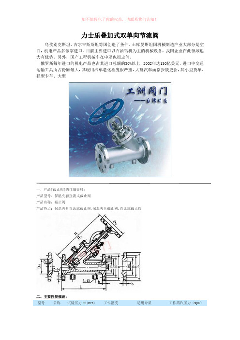
力士乐叠加式双单向节流阀乌孜别克斯坦、吉尔吉斯斯坦等国创造了条件。
土库曼斯坦国机械制造产业大部分是空白,机电产品多依靠进口,目前主要进口以石油钻机为主的机械设备,我国企业在此领域也大有优势。
另外,国产工程机械车在中亚也很走俏。
俄罗斯每年进口的机电产品也占其进口总额的30%以上,2002年达130亿美元,进口中交通运输工具所占份额最大,其现用汽车老化程度很严重,大批汽车面临报废更新,其小型货车、轻型卡车、大型一、产品[截止阀]的详细资料:产品型号:保温夹套直流式截止阀产品名称:截止阀产品特点:保温夹套直流式截止阀,保温夹套截止阀,直流式截止阀二、主要性能规范:型号公称试验压力PS(MPa)工作温度适用介质工作蒸汽压力(Mpa)(压力PN(Mpa)℃)壳体密封(水) BJ45W-25P 2.5 3.75 2.75 ≤200硝酸类≤1.0BJ45W-40P 4.0 6.0 4.4 BJ45W-64P 6.4 9.0 6.6BJ45W-25P 2.5 3.75 2.75 醋酸类BJ45W-40P 4.0 6.0 4.4 BJ45W-64P 6.49.06.6二、工洲牌保温夹套直流式截止阀主要尺寸:公称压力PN( MPa )公称通径DN (mm ) 尺寸(mm ) LD D1D2D3b1f0bD63-G Z-φD H H1 DO 2.5 4.015 170 105 75 55 35 8 4 16 51 3/8 4-φ14 250 262 120 20 190 115 85 65 42 8 4 16 58 3/8 4-φ14 292 308 140 25 210 135 100 78 50 8 4 18 66 3/8 4-φ18 340 375 160 32 230 145 110 85 60 8 4 18 76 1/2 4-φ18 338 375 160 40260 160 125 100 72 8 4 20 88 1/2 4-φ18 360 386 160 50 300 180 145 120 94 8 4 22 110 1/2 4-φ18 410 450 240 65 340 195 160 135 105 8 4 22 121 1/2 4-φ18 440 485 240 80 380 230 190 160 128 11 4.5 24 150 1/2 4-φ23 540 600 280 100 430 270 220 188 154 11 4.5 28 176 1/2 4-φ25 560 625 320 125 490 300 250 218 182 11 4.5 30 204 1/2 4-φ25 625 737 360 150550330280248212114.5322041/24-φ25720790360三、主要零件材料:零件名称阀体、阀盖阀关瓣垫片JB45W-25P\BJ45W-40P\BJ45W-64P铬镍钛钢铬镍钛钢+硬质合金聚四氟乙烯JB45W-25P\BJ45W-40P\BJ45W-64P铬镍钼钛钢铬镍钼钛钢+硬质合金聚四氟乙烯一、产品[截止阀]的详细资料:产品型号:JIS型产品名称:截止阀产品特点:截止阀价格,截止阀厂家,截止阀报价该阀门采用弹性V形聚四氟乙烯或丁晴橡胶作为动密封填料,由填料盖/不锈钢弹簧提供初始密封,填料密封性能随介质压力上升而增强,既具有密封性能,无需人工维护。
力士乐减速机样本

INDICE INDEX INHALTSVERZEICHNISA Informazionigenerali GeneralinformationAllgemeineInformationen1SIMBOLOGIA SYMBOLS VERWENDETE SYMBOLE A-2 2IDENTIFICAZIONE DELPRODOTTOPRODUCT IDENTIFICATION PRODUKTKENNZEICHNUNG A-4 3CARATTERISTICHE TECNICHE TECHNICAL CHARACTERISTICS TECHNISCHE BESCHREIBUNG A-84SELEZIONE DEI RIDUTTORI RUOTA SELECTION OF THE WHEELGEARSAUSWAHL VOM RADNABEN-GETRIEBEA-185SCELTA DEL MOTORE IDRAU-LICO CHOOSING THE HYDRAULICMOTORAUSWAHL VOM HYDRAULIK-MOTORA-286VERIFICHE CHECKS KONTROLLEN A-30 7LUBRIFICAZIONE LUBRICATION SCHMIERUNG A-328IMBALLO, MOVIMENTAZIONE E STOCCAGGIO PACKING, HANDLING ANDSTORINGVERPACKUNG, TRANSPORTUND LAGERUNGA-389MONTAGGIO ASSEMBLY MONTAGE A-42 10CONTROLLI CHECKS KONTROLLEN A-46 11DISINNESTO DISENGAGEMENT AUSKUPPLUNG A-48 12MANUTENZIONE MAINTENANCE WARTUNG A-48 13INCONVENIENTI E RIMEDI TROUBLESHOOTING FUNKTIONSSTÖRUNGEN UNDBEHEBUNGA-52 14COPPIE IN USCITA OUTPUT TORQUES AUSGANGSDREHMOMENTE A-54B Dati tecnici edimensionali Technical and size data Technische Daten undAbmessungenRRTD RRTD RRTD B-3 RRWD RRWD RRWD B-15C Configurazioni entratae accessori iningresso Inlet configurations andaccessories in inputEingangskonfigurationund Zubehör im Eingang15FLANGIATURA PER MOTORE A NORME SAEJ 744C FLANGING FOR MOTOR TOSAEJ 744C STANDARDSFLANSCHUNG FÜR MOTOR NACHNORM SAEJ 744C C-216CONNESSIONE MOTORI CONNECTION OF MOTORS ANSCHLUSS MOTOR C-3 17RUOTE SPECIALI CUSTOMIZED WHEEL GEARS SONDERNGETRIEBE C-41SYMBOLES SIMBOLOGÍA SIMBOLOGIA A-32IDENTIFICATION DU PRODUIT IDENTIFICACIÓNDEL PRODUCTOIDENTIFICAÇÃODO PRODUTOA-53CARACTERISTIQUES TECHNIQUES CARACTERÍSTICASTÉCNICASCARACTERÍSTICASTÉCNICASA-94CHOIX DES REDUCTEURS ROUE SELECCIÓN DE LOS REDUC-TORES DE RUEDA SELECÇÃO DOS REDUTORESDA RODAA-195CHOIX DU MOTEUR HYDRAU-LIQUE SELECCIÓN DEL MOTORHIDRÁULICOESCOLHA DO MOTOR HI-DRÁULICOA-296VERIFICATIONS COMPROBACIONES VERIFICAÇÕES A-31 7 LUBRIFICATION LUBRICACIÓN LUBRIFICAÇÃO A-338EMBALLAGE, MANUTENTION ET STOCKAGE EMBALAJE, DESPLAZA-MIENTO Y ALMACENAMIENTOEMBALAGEM, MOVIMENTA-ÇÃO E ARMAZENAGEMA-399MONTAGE MONTAJE MONTAGEM A-43 10CONTROLES COMPROBACIONES CONTROLES A-47 11DEBRAYAGE DESEMBRAGUE DESENGATE A-49 12ENTRETIEN MANTENIMIENTO MANUTENÇÃO A-49 13INCONVENIENTS ET REMEDES INCONVENIENTES Y REMEDIOS INCONVENIENTES E SO-LUÇÕESA-53 14 COUPLES EN SORTIE PARES EN SALIDA PARES À SAÍDA A-54B Données techniqueset dimensionnelles Datos técnicos ydimensionalesDados tècnicos edimensŏesRRTD RRTD RRTD B-3 RRWD RRWD RRWD B-15C Configurations enentrée et accessoiresd’entrée Configuraciones deentrada y accesorios enentradaConfigurações à entradae acessórios à entrada15BRIDAGE POUR MOTEUR AUX NORMES SAEJ 744C BRIDAS PARA MOTOR SEGÚNNORMAS SAEJ 744CENTREAJUDAS PARA MOTORDE ACORDO COM AS NORMASSAEJ 744CC-216CONNEXION MOTEURS CONEXIÓN MOTORES CONEXÃO MOTORES C-3 17ROUES PERSONNALISÉES RUEDA PERSONALIZADOS RODA ESPECIAL C-4A Informazioni generaliGeneral information Allgemeine Informationen Informations générales Información generalInformações gerais1 SIMBOLOGIA 1 SYMBOLS 1 VERWENDETE SYMBOLE2 IDENTIFICAZIONE DEL PRODOTTO 2.1 Composizione di montaggio 2 PRODUCT IDENTIFICATION2.1 Assembly composition2 PRODUKTKENNZEICHNUNG2.1 Montage2.2 DesignazioneI riduttori ruota Reggiana Riduttori ven-gono identificati mediante una sigla com -posta nel seguente modo:2.2 DesignationThe Reggiana Riduttori wheel gears are identified by an acronym made up in the following way:2.2 BezeichnungDie Radnabengetriebe von Reggiana Riduttori sind durch einen Code gekenn-zeichnet, der folgende Bedeutung hat:2.3 Marcatura del prodotto e designazione del tipoTutti i prodotti Reggiana Riduttori sono dotati di targhetta metallica di identifica -zione, posizionata in modo da risultare facilmente leggibile, anche dopo l’instal-lazione.La seguente figura mostra un esempio di targhetta.LegendaLegendLegendeA Tipo di riduttore ruota (sigla)Wheel gear type (acronym)Typ Radnabengetriebe (Kürzel)B Codice identificativo di ordi -nazioneID code for ordering Identifizierungscode der BestellungC Rapporto di riduzione Reduction ratio UntersetzungsverhältnisD Coppia frenante Braking torqueBremsmomentE N° di ordine Order NumberAuftragsnummerN° progressivo di matricola e Progressive serial number Fortlaufende Seriennummer2.3 Product marking and type designationAll Reggiana Riduttori products have a metal id plate positioned so as to be eas-ily readable also after installation.The following figure shows an example of a plate.2.3 Produktkennzeichnung und TypenschildAlle Produkte von Reggiana Riduttori weisen ein Typenschild aus Metall auf, das so angebracht ist, dass es auch nach der Installation leicht abgelesen werden kann.Die Abbildung unten zeigt ein Beispiel.Leistungen Negativbremse Ohne Negativbremse Prefisso invariabile / Invariable prefix / Fixes Vorzeichen RR = REGGIANA RIDUTTORI2.3 Marquage du produitet désignation du typeSur tous les produits Reggiana Riduttori, une plaquette métallique d’identification est appliquée. Elle est positionnée de manière à être facile à lire, même une fois le réducteur installé.La figure suivante montre un exemple de la plaquette.2.3 Marcado del productoy denominación del tipoTodos los productos Reggiana Riduttorillevan una placa metálica de identifica-ción, colocada de manera que resultefácilmente legible, también después dela instalación.La siguiente figura presenta un ejemplode placa.2.3 Marcação do produtoe designação do tipoTodos os produtos Reggiana Riduttorisão munidos de placa metálica de iden-tificação, colocada de modo a ser lidacom facilidade, também depois da insta-lação.A seguinte figura ilustra um exemplo deplaca.Légende Leyenda LegendaA Type de réducteur roue (sigle)Tipo de reductor (sigla)Tipo de redutor (referência)B Code d’identification de lacommandeCódigo identificador depedidoCódigo identificativo deencomendaC Rapport de réduction Relación de reducción Relação de reduçãoD Couple freinant Par frenador Par de freioE N° de commande N° de pedido N° de ordemF N° progressif de série et année N° progresivo de matrícula y N° progressivo de matrículaPréfixe invariable / Prefijo invariable / Indicativo invariável RR = REGGIANA RIDUTTORI3 CARATTERISTICHE TECNICHE3.1 Funzioni generali, gamma di appli- cazioni e utilizzo previstoI riduttori ruota Reggiana Riduttori sono progettati per realizzare la trasmissione di potenza all’interno di macchine opera-trici. Essi possono essere collegati diret-tamente ad un motore di tipo elettrico o idraulico.I riduttori ruota vengono utilizzati nell’am-bito di diverse applicazioni, sia industriali che mobili, tra le quali: industria mecca-nica, industria chimica e plastica, indu-stria alimentare, edilizia e costruzioni, industria estrattiva, agricoltura e foreste, trasporti e sollevamento, settore marino, generatori eolici di energia.Utilizzare il riduttore soltanto per gli usi previsti in fase di progetto. L’impiego per usi impropri può essere causa di pericolo per la sicurezza e la salute delle persone. Gli usi previsti sono quelli industriali e mobili per i quali sono stati sviluppati e costruiti i riduttori.3.2Coppia in uscitaT2n[Nm]È il valore di coppia trasmissibile, in funzionamento continuo e uniforme, pari ad una durata teorica di 30000 n2.h. I valori di T2sono riportati nelle schede tecniche di ogni riduttore ruota. La coppia T2 è limitata dalla resistenza a flessione o dalla resistenza superficiale dei denti degli ingranaggi, in accordo con la norma ISO 6336.3.3Coppia in uscita massimaT2max [Nm]Rappresenta il valore di coppia massi-ma applicabile in uscita al riduttore ruota per brevi durate o per picchi occasiona-li, senza il verificarsi di danneggiamenti permanenti agli elementi più sollecitati.3.4Coppia in uscita richiestaT2r [Nm]È il valore di coppia in uscita che si inten-de applicare al riduttore ruota, in base ai dati di funzionamento dell’applicazione.3 TECHNICAL CHARACTERISTICS3 TECHNISCHE BESCHREIBUNG 3.1 General functions, range ofapplications and intended useThe Reggiana Riduttori wheel gears aredesigned for transmitting power insideoperating machines. They can be con-nected directly to either an electric or hy-draulic motor.The wheel gears are used for many dif-ferent types of application, both indus-trial and mobile some of which are: themechanical industry, the chemical andplastics industry, the food industry, build-ing and constructions, mining industry,agriculture and forestry, transporting andlifting, marine sector, wind generators ofenergy.Use the reduction gear only for the usescontemplated in the project phase. Usingit improperly can be the cause of dangerfor the safety and health of people.The reduction gears have been designedand made for the industrial and mobileuses.Die Radnabengetriebe dürfen nur für denvom Hersteller vorgesehenen Zweck ver-wendet werden. Bei unsachgemäßemGebrauch kann die Sicherheit und Ge-sundheit von Personen gefährdet werden.Unter vorgesehenem Gebrauch werdendie industriellen und mobilen Anwendun-gen verstanden, für die die Getriebe ent-wickelt und gebaut worden sind.3.1 Allgemeine Funktionen, Anwen-dungsbereiche und vorgeseheneAnwendungDie Radnabengetriebe von Reggia-na Riduttori werden für die Leistungs-übertragung im Inneren von Arbeits-maschinen konzipiert und gefertigt.Sie können direkt an einen Elektromotoroder einen Hydraulikmotor angeschlos-sen werden.Die Radnabengetriebe werden sowohlin der Industrie, als auch im Fahrzeug-bau in verschiedenen Anwendungeneingesetzt, darunter: Maschinenbau,chemische und Kunststoff verarbeitendeIndustrie, Lebensmittelindustrie, Bau-wirtschaft, Bergbau, Land- und Forst-wirtschaft, Transport- und Hubtechnik,Schiffbau, Windkraftanlagen.3.2 Output torqueT2n [Nm]This is the value of the torque which canbe transmitted in continuous and uniformoperation equalling a theoretical life of30000 n2.h. The T2values are given inthe technical data sheets of each wheelgear. T2torque is limited by resistanceto bending or by the surface resistanceof gear teeth, in agreement with the ISO6336 standard.3.3 Maximum output torqueT2max [Nm]It is the maximum torque value applicableto wheel gear output for short lengths oftime or for occasional peaks, without anypermanent damage to the most stressedelements.3.4 Required output torqueT2r[Nm]It is the torque value in output you intendapplying to the wheel gear, based on theapplication’s operating data.3.2AusgangsdrehmomentT2n[Nm]Dabei handelt es sich um das übertrag-bare Drehmoment bei gleichmäßigemDauerbetrieb, das einer theoretischenDauer von 30000 n2.h entspricht. DieWerte vom Drehmoment T2sind in dentechnischen Datenblättern der einzel-nen Radnabengetriebe angegeben. DasDrehmoment T2wird nach Vorgabe derNorm ISO 6336 vom Biegewiderstandoder vom Oberflächenwiderstand derZähne vom Getriebe begrenzt.3.3Maximales AusgangsdrehmomentT2max [Nm]Dabei handelt es sich um den Wertvom Drehmoment, das maximal amAusgang des Radnabengetriebes fürkurze Zeit oder gelegentliche Spitzenangelegt werden kann, ohne dass dieszu einer dauerhaften Schädigung deram stärksten Belasteten Bauteile führt.3.4Verlangtes AusgangsdrehmomentT2r [Nm]Dabei handelt es sich um das Ausgangs-drehmoment, das an das Radnabenge-triebe je nach Funktionswerten der An-wendung angelegt werden soll.applications, aussi bien dans le domaine industriel que mobile, parmi lesquelles: l’industrie mécanique, l’industrie chimi-que et plastique, l’industrie alimentaire, le bâtiment et les constructions, l’industrie extractive, l’agriculture et la sylviculture, le transport et les systèmes de levage, la marine, les générateurs éoliens.N’utiliser le réducteur que pour les usa-ges pour lesquels il a été projeté. Son utilisation impropre peut être cause de danger pour la sécurité et la santé des personnes.Les usages prévus sont les emplois in-dustriels et mobiles pour lesquels les ré-ducteurs ont été élaborés et fabriqués.3.2 Couple de sortie T 2n [Nm]C’est la valeur du couple qui peut être transmis dans des conditions de fonc-tionnement continu et uniforme équiva-lant à une durée théorique de 30000 n 2xh. Les valeurs de T 2 sont indiquées sur les fiches techniques de chaque réducteur roue.Le couple T 2 est limité par la résistance à la flexion ou par la résistance de la sur -face des dents des engrenages, confor-mément à la norme ISO 6336.3.3 Couple à la sortie maximum T 2max [Nm]Il représente la valeur de couple maxi-mum applicable à la sortie au réducteur pour de courtes durées ou pour des pics occasionnels, sans provoquer de dom-mages permanents aux éléments les plus sollicités.3.4 Couple de sortie demandé T 2r [Nm]C’est la valeur de couple de sortie qu’on souhaite appliquer au réducteur roue, en fonction des données de fonctionnement de l’application.el ámbito de distintas aplicaciones, tanto industriales como móviles, entre las cua-les: industria mecánica, industria quími-ca y del plástico, industria alimentaria, de la construcción, industria minera, agricul-tura y forestal, transportes y elevación, sector marítimo, generadores eólicos deenergía.Utilizar el reductor sólo para los usos pre-vistos en la fase de proyecto. La utiliza-ción para usos no adecuados puede cau-sar peligros para la seguridad y la salud de las personas.Los usos previstos son aquellos indus-triales y móviles para los cuales han sido desarrollados y construidos los reducto-res.Usar o redutor exclusivamente para os usos previstos na fase de projecto. O emprego em usos impróprios pode ser causa de perigo para a segurança e a saúde das pessoas.Os usos previstos são aqueles industriais e móveis para os quais os redutores fo-ram concebidos e construídos.âmbito de várias aplicações, quer indus-triais quer móveis, entre as quais: indús-tria mecânica, indústria química e dos plásticos, indústria alimentar, constru-ção civil, indústria minerária, agricultura e florestas, transportes e levantamento, sector marítimo, geradores eólicos de energia.3.2 Par en salida T 2n [Nm]Es el valor del par transmisible en fun-cionamiento continuo y uniforme, equi-valente a una duración teórica de 30000 n 2 x h. Los valores de T 2 son indicados en las fichas técnicas de cada reductor de rueda.El par T 2 está limitado por la resistencia a la flexión o por la resistencia superficial de los dientes de los engranajes, según la norma ISO 6336.3.3 Par en salida máximo T 2max [Nm]Representa el valor de par máximo apli-cable en salida al reductor de rueda por breves duraciones o por picos ocasio-nales, sin que se produzcan daños per-manentes a los elementos mayormente bajo esfuerzo.3.4 Par en salida requerido T 2r [Nm]Es el valor de par en salida que se de-sea aplicar al reductor de rueda, sobre la base de los datos de funcionamiento de la aplicación.3.2 Par à saída T 2n [Nm]É o valor de par transmissível, em fun-cionamento contínuo e uniforme,igual a uma duração teórica de 30000 n 2.h .Os valores de T 2 são indicados nas fi -chas técnicas de cada redutor da roda.O par T 2 é limitado pela resistência à flexão ou pela resistência superficial dos dentes das engrenagens, de acordo com a norma ISO 6336.3.3 Par em saída máximo T 2max [Nm]Representa o valor de par máximo aplicá-vel em saída ao redutor por breves perío-dos ou por picos ocasionais, sem que se verifiquem danos permanentes nos ele -mentos mais solicitados.3.4 Par à saída exigido T 2r [Nm]É o valor de par à saída que se tenciona aplicar ao redutor da roda, com base nos dados de funcionamento da aplicação.3.5 Velocità in entrata n 1 [min -1]È la velocità del motore collegato in in-gresso al riduttore ruota.3.6 Velocità in uscita n 2 [min -1]È la velocità in uscita del riduttore, fun-zione della velocità in entrata n 1 e del rapporto di riduzione effettivo i.3.7 Rapporto di riduzione iIndica l’effettivo rapporto tra la velocità in entrata n 1 e la velocità in uscita n 2 del riduttore ruota:I rapporti di riduzione disponibili sono riportati nella tabella dei dati tecnici per ogni grandezza di riduttore ruota. Su ri-chiesta è possibile ottenere ulteriori rap-porti di riduzione.3.8 Velocità in entrata massima n 1max [min -1]Indica la velocità massima ammessa in entrata per brevi durate o in funziona-mento intermittente; la velocità in entrata del riduttore ruota è limitata dalla velocità periferica degli ingranaggi, dai cuscinetti e dalle tenute.3.9 Verso di rotazioneIn generale, per ogni riduttore ruota di questo catalogo, l’uscita gira in senso opposto all’albero entrata. Fa eccezione il riduttore ruota RRWD270/B nel quale, a causa del particolare funzionamento interno, l’uscita gira nello stesso senso dell’ingresso.3.10 Potenza in entrata P 1 [kW]È la potenza applicata in ingresso al ri-duttore ruota, mediante collegamento diretto di un motore.3.5 Input speed n 1 [min -1]It is the speed of the motor connected to the wheel gear at input.3.6 Output speed n 2 [min -1]It is the reduction gear’s output speed as a function of the input speed n 1 and of the actual reduction ratio i.3.7 Reduction ratio iIt indicates the actual ratio between the wheel gear’s input speed n 1 and output speed n 2:The reduction ratios available are given in the technical data table for each wheel gear size. Other reduction ratios can be obtained on request.3.8 Maximum input speed n 1max [min -1]It indicates the maximum permitted input speed for short lengths of time or intermit-tently; the wheel gear’s input speed is lim-ited by the peripheral speed of the gears, by the bearings and by the seals.3.9 Rotation directionGenerally, for each wheel gear in this cat-alogue, the output turns in the opposite direction to the input shaft. An exception to this rule is wheel gear RRWD270/B where, due to its particular internal work-ing, the output turns in the same direction as the input.3.10 Input power P 1 [kW]It is the power applied to the wheel gear at input by means of the direct connec-tion of a motor.3.5 Eingangsgeschwindigkeit n 1 [min -1]Dabei handelt es sich um die Geschwin-digkeit vom Motor, der am Eingang vom Radnabengetriebe angeschlossen ist.3.6 Ausgangsgeschwindigkeit n 2 [min -1]Dabei handelt es sich um die Geschwin-digkeit der Ausgangswelle vom Radna-bengetriebe, die sich aus der Eingangs-geschwindigkeit n 1 und dem effektiven Untersetzungsverhältnis i ergibt.3.7 Untersetzungsverhältnis iDabei handelt es sich um das effektive Verhältnis von Eingangsgeschwindigkeit n 1 zu Ausgangsgeschwindigkeit n 2 vom Radnabengetriebe:Die verfügbaren Untersetzungsverhält-nisse sind für jede Größe vom Radna-bengetriebe in der Tabelle mit den tech-nischen Daten zusammengestellt. Auf Wunsch sind weitere Untersetzungsver-hältnisse erhältlich.3.8 Maximale Eingangsgeschwindigkeit n 1max [min -1]Dabei handelt es sich um die maximal zulässige Eingangsgeschwindigkeit für kurze Dauer oder bei unterbrochenem Betrieb. Die Eingangsgeschwindigkeit vom Radnabengetriebe ist durch die Pe-ripheriegeschwindigkeit von Zahnrädern, Lagern und Dichtungen beschränkt.3.9 RotationsrichtungAllgemein gilt für jedes Radnabengetrie-be des vorliegenden Katalogs, dass sich der Ausgang in die entgegen gesetzte Richtung dreht wie die Eingangswelle. Eine Ausnahme bildet das Radnaben-getriebe RRWD270/B, bei welchem sich aufgrund der speziellen Bauweise der Ausgang in die gleiche Richtung wie die Eingangswelle dreht.3.10 Eingangsleistung P 1 [kW]Dabei handelt es sich um die Leistung, die am Eingang vom Radnabengetriebe durch den direkten Anschluss an einen Motor angelegt wird.du réducteur, en fonction de la vitesse à l’entrée n 1 et du rapport de réduction ef-fectif i.3.7 Rapport de réduction iIl indique le rapport effectif entre la vites-se à l’entrée n 1 et la vitesse à la sortie n 2 du réducteur roue:Les rapports de réduction existants sont indiqués dans le tableau des caractéris-tiques techniques pour chaque grandeur de réducteur roue. Sur demande, il est possible d’obtenir des rapports de réduc-tion supplémentaires.3.8 Vitesse à maximum à l’entrée n 1max [min -1]Elle indique la vitesse maximum admise à l’entrée pour de courtes durées ou en fonctionnement intermittent; la vitesse à l’entrée du réducteur roue est limitée par la vitesse périphérique des engrenages, par les roulements et les garnitures.3.9 Sens de rotationEn général, pour tous les réducteurs roue de ce catalogue, l’arbre de sortie tourne dans le sens inverse de celui de l’arbre d’entrée, à l’exception du réducteur roue RRWD270/B dans lequel, en raison du fonctionnement interne particulier, l’arbre de sortie tourne dans le même sens que l’arbre d’entrée.3.10 Puissance à l’entrée P 1 [kW]C’est la puissance appliquée à l’entrée du réducteur roue, par un raccord direct d’un moteur.función de la velocidad en entrada n 1 y de la relación de reducción efectiva i.3.7 Relación de reducción iIndica la efectiva relación entre la veloci-dad en entrada n 1 y la velocidad en sali-da n 2 del reductor de rueda:Las relaciones de reducción disponibles se indican en la tabla de los datos técni-cos para cada talla de reductor de rueda. Bajo demanda es posible obtener ulterio-res relaciones de reducción.3.8 Velocidad en entrada máxima n 1max [min -1]Indica la velocidad máxima admitida en entrada por breves duraciones o en fun-cionamiento intermitente; la velocidad en entrada del reductor de rueda está limitada por la velocidad periférica de los engranajes, por los cojinetes y por las estanqueidades.3.9 Sentido de giroEn general, para cada reductor de rueda de este catálogo, la salida gira en senti-do opuesto al eje de entrada.La excepción es el reductor de rueda RRWD270/B en el cual, debido al funcio-namiento interno particular, la salida gira en el mismo sentido que la entrada.3.10 Potencia en entrada P 1 [kW]Es la potencia aplicada en entrada al re-ductor de rueda, mediante conexión di-recta de un motor.tor, função da velocidade em entrada n 1 e da relação de redução efetiva i.3.7 Relação de redução iIndica a efectiva relação entre a veloci-dade em entrada n 1 e a velocidade em saída n 2 do redutor da roda:As relações de redução disponíveis es-tão indicadas na tabela dos dados téc-nicos para cada grandeza do redutor da roda. A pedido, é possível obter outras relações de redução.3.8 Velocidade em entrada máxima n 1max [min -1]Indica a velocidade máxima admitida em entrada por breves períodos ou em funcionamento intermitente; a veloci-dade em entrada do redutor da roda é limitada pela velocidade periférica das engrenagens, pelos rolamentos e pelas vedações.3.9 Direcção de rotaçãoEm geral, para cada redutor da roda des-te catálogo, a saída rodeia em sentido contrário à árvore da entrada.Com excepção do redutor da roda RRWD270/B no qual, devido ao funcio-namento especial interno, a saída rodeia no mesmo sentido da entrada.3.10 Potência em entrada P 1 [kW]É a potência aplicada à entrada ao redu-tor da roda, mediante ligação directa de um motor.3.12 Rendimento ηE' un coefficiente adimensionale dato dal rapporto tra la potenza in uscita P 2 e quella in entrata P 1:Il valore di rendimento di un singolo sta-dio di riduzione, in condizioni medie di velocità e coppia, è pari a 0.975; tale valore decresce nel caso di: incremento della velocità, diminuzione della coppia trasmessa, aumento della temperatura ambiente.3.13 Carico radiale in uscita F r2 [N]In corrispondenza di ogni singola sche-da tecnica è riportata la curva dei carichi radiali ammissibili F r,2 in funzione della ascissa x (distanza da un riferimento op-portuno). Il valore di carico radiale am-missibile è riferito ad una durata dei cu-scinetti, calcolata in base alla norma ISO 281, pari a 300000 n 2.h.Tutte le curve dei carichi radiali ammis-sibili sono state fatte imponendo che i carichi assiali F a,2 siano nulli.3.14 Carico assiale in uscita F a,2 [N]Su tutte le tipologie di riduttore ruota è ammessa la presenza di un carico assia-le in verso entrante o uscente.In presenza di carico assiale, verificare l’idoneità del riduttore ruota contattando il Servizio Tecnico Reggiana Riduttori.3.12 Efficiency ηIt is a dimensionless coefficient given by the ratio between the output powerP 2 and input power P 1:The efficiency value of a single reduction stage under average speed and torque conditions, is equivalent to 0.975; this value decreases if: speed increases, transmitted torque diminishes, ambient temperature increases.3.13 Radial load in output F r2 [N]The curve of the permissible radial loads F r,2 as a function of abscissa x (distance from a suitable reference) is given whe-re each single technical datasheet is. The permissible radial load value refers to bearing life calculated on the basis of the ISO281 standard which is equal to 300000 n 2.h.All curves of the permissible radial loads have been done taking the axial loads F a,2 as nil.3.14 Output axial load F a,2 [N]An axial load, in input or output, is al-lowed on all wheel gear types.When there is an axial load check that the wheel gear is suitable, contacting the Reggiana Riduttori Technical Service.3.12 Wirkungsgrad ηDabei handelt es sich um einen dimen-sionslosen Wert, der sich aus dem Ver-hältnis der Ausgangsleistung P 2 zur Eingangsleistung P 1 ergibt:Der Wert vom Wirkungsgrad einer ein-zelnen Untersetzungsstufe bei mittle-rer Geschwindigkeit und Drehmoment entspricht 0.975. Dieser Wert nimmt bei zunehmender Geschwindigkeit, abneh-mendem anliegendem Drehmoment und zunehmender Umgebungstemperatur ab.3.13 Querlast am Ausgang F r2 [N]In den einzelnen technischen Datenblät-tern ist die Kurve der zulässigen Quer-lasten F r,2 in Abhängigkeit der X-Achse (Abstand von einem geeigneten Bezugs-punkt) abgetragen. Der Wert der zuläs-sigen Querlast bezieht sich auf eine Le-bensdauer der Lager von 300000 n 2.h., die nach Vorgabe der Norm ISO 281 be-rechnet wird.Alle Kurven der zulässigen Querlasten wurden unter der Voraussetzung erstellt, dass die Achslasten F a,2 gleich Null sind.3.14 Achslast am Ausgang F a,2 [N]An allen Radnabengetrieben ist eine Achslast in Eingangs- oder Ausgangs-richtung zulässig.Bei Achslast die Eignung vom Radna-bengetriebe prüfen und dazu den Tech-nischen Kundendienst von Reggiana Ri-3.11 Potenza in uscita P 2 [kW]È la potenza richiesta dall’utilizzatore col-legato in uscita al riduttore ruota. Si può calcolare come: 3.11 Output power P 2 [kW]It is the power required by the user con-nected to the wheel gear in output. It can be calculated as:3.11 Ausgangsleistung P 2 [kW]Dabei handelt es sich um die Leistung, die vom Abnehmer verlangt wird, der am Ausgang vom Radnabengetriebe an-geschlossen ist und wie folgt berechnet wird:。
Rexroth力士乐液压泵样本说明
Rexroth Rexroth力士乐液压泵样本说明力士乐液压泵样本说明A11VO 2177-e / 08.99上海市东洋液压油泵有限公司联系人:江海电话:021-******** 400-001-8191传真:021-********手机:158********QQ :397049931QQ :2269925193网址: 邮箱:shdypump@地址:上海市嘉定区安亭镇墨玉路28号嘉正国际1301-1305邮编:201805认识A11V(L)OL)O各种控制块泵头阀通轴驱动吸油离心泵可选的泵摆角指示器Size A11VO40607595130190260A11VLO130190260 Speed 30003000270025502350210021001800250025002300350 / 400 barPressure 350 / 400 bar认识A11V (L)O L)O制造商订货型号生产日期轴向柱塞元件的材料号 序列号旋向(从轴端看,此处为逆时针 )A11VO ControllersA11VLO...LRDS功率调节螺钉负载敏感压差压力切断最小排量调节最大排量调节A11VO Controllers Load Sensing LRDS负载感应压力切断功率调节主控制阀块 M4, M7(负载感应节流孔)∆porificeA11VO Controllers恒功率调节原理F1*L1=F2*L2F1*L1=C-恒定值(P*A)*L1=C(P*A)*q=CP*Q=C/AP*Q=功率=恒定值油泵的安装和初次启动过程中的注意事项�液压系统装配前,必须保证油箱、胶管、接头等元件清洁。
油箱内是否有焊渣、铁屑、抹布等杂质;清理油箱最简单有效的办法,用面团粘。
胶管在加工过程中内壁不可避免附着橡胶颗粒以及铁屑,所以胶管必须经过冲洗才能安装到系统中。
�装配过程中,注意防尘,避免二次污染。
比如,液压装配现场不能进行打磨,喷漆等产生粉尘的工作;装配过程中注意各管口、法兰口的密封防尘,只有在连接时才打开防尘盖;停止施工时必须封堵管口。
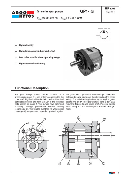
力士乐齿轮泵样本
10 17 27 34 43 51 61 71 82 100 F
B
Flange SAE B (SAE J744C)
O
Pressure Ports O-ring Ports to SAE J1926 (ISO 11926)
Suction Ports Flange face to SAE J518
Direction of rotation: Clockwise Counterclockwise
Pressure p2 in PSI (bar)
Nominal Size 82
Flow Q in GPM (L/min)
Power in Hp (kW)
Pressure p2 in PSI (bar)
Pressure p2 in PSI (bar)
5
HU 8001
Performance Data
Nominal Size 100
Functional Description
The gear Pumps Series GP1-Q consists of 2 intermeshing gears (1), one of them connected to the drive shaft. Right or Left hand rotation on the drive shaft generates pressure and flow as given in the technical data section on page 2. The pumps have optimized efficiency through pressurized internal sealing technology (2). The floating bushings (3) with special bearings (4) are pressure dependent pushed against the gears which guarantee minimum gap clearance between bushing and gears thereby sealing the gears axially. The radial sealing is done by forcing the gears against the body. The gear pumps have 2-Bolt SAE mounting flange (5) and keyed shaft. Pressure port is SAE O-Ring Port and Suction ports are SAE - Flange Ports.
力士乐换向阀样本

3.2
!" #$%&'()*+,./0,12 !" #$%& '8 !"#$ !"#$%&'()*Y !"#$%#& '( )%#* +Y
!" #$ %&' (9 !"#$%!&' !"#$% &10 !"#
!"
3/22
308
RC 24 751/03.97
!"#$%
3
!"#$%&'()*+,-. /01 4WEH...H ! " #2 !"#$%&'()*+,!"# 12 !"#$%&'()*+,!"#$%&'()* ! +2 !"# !"#$%&'(#)%& *+Y
!"
3
2.2
4WE 6 Y... !"# !"#$%& Y HY 4WE 6 J... !" #b !"#$%&EB FB 4WE 6 M... !" #b !"#$%& HEB HFB
!"# !
2.3
3.1 3.2 4
4WE 6 J... !"# !"#$%&'( 4WE 6 M... !"# !"#$%&'( !a ( !) !b ( !) !"# $N !" !"#$%&'()*50 bar !"#$%&'()*+ !"#$%&'( ! "4WH... !"#$% !"# $A/F6 !" !"#$
力士乐平衡阀样本
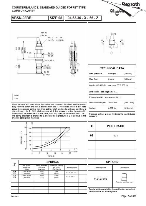
When pressure at 2 rises above the spring bias pressure, the check seat is pushed away from the piston and flow is allowed from 2 to 1. When load pressure at 1 rises above the pressure setting, the direct-acting, relief function is activated and flow is relieved from 1 to 2. With pilot pressure at 3, the pressure setting is reduced in proportion to the stated ratio of the valve, until fully open with free-flow from 1 to 2. The spring chamber is drained to 2, and any back-pressure at 2 is additive to the pressure setting in all functions.SPRINGSZ Adj. press.range psi(bar)Press. increasepsi / turn(bar/turn)Standard settingpsi (bar)(Q=5 l/min)Ordering code201450-3000(100-210)1581(109)2900(200)03.51.01.328352900-5000(200-350)1987(137)5000(350)03.51.01.327TECHNICAL DATAPressure setting: at least 1.3 times the load inducedpressureMax. pressure: 5000 psi(350 bar)Max. flow: 8 gpm (30 l/min)Cavity : CA-08A-3N(see page CT.A.003.U)Line bodies : see page MN1.A…External seal kit : see page A11.011Installation torque : 25-30 ft-lb (34-41 Nm)Weight: 0.397 lbs (0.180 Kg)X PILOT RATIO03 4 : 1OPTIONSOrdering code Description11.04.23.002Tamper resistant capWhen pressure at 2 rises above the spring bias pressure, the check seat is pushed away from the piston and flow is allowed from 2 to 1. When load pressure at 1 rises above the pressure setting, the direct-acting, differential area relief function is activated and flow is relieved from 1 to 2. With pilot pressure at 3, the pressure setting is reduced in proportion to the stated ratio of the valve, until fully open with free-flow from 1 to 2. The spring chamber is drained to 2, and any back-pressure at 2 is additive to the pressure setting in all functions.SPRINGSZ Adj. press.range psi(bar)Press. increasepsi / turn(bar/turn)Standard settingpsi (bar)(Q=5 l/min)201000-3000(70-210)1958(135)2900(200)X= 03352000-5000(140-350)2842(196)5000(350)201000-3000(70-210)754(52)2900(200)X= 10352000-5000(140-350)1291(89)5000(350)TECHNICAL DATAPressure setting: at least 1.3 times the load inducedpressureMax. pressure: 5000 psi(350 bar)Max. flow: 16 gpm (60 l/min)Cavity : CA-10A-3C(see page CT.A.002.U)Line bodies : see page MN1.A…External seal kit : see page A11.011Installation torque : 30-35 ft-lb (41-47 Nm)Weight: 0.441 lbs (0.200 Kg)X PILOT RATIO03 3 : 1108 : 1OPTIONSOrdering code Description11.04.23.002Tamper resistant capWhen pressure at 2 rises above the spring bias pressure, the check seat is pushed away from the piston and flow is allowed from 2 to 1. When load pressure at 1 rises above the pressure setting, the direct-acting, differential area relief function is activated and flow is relieved from 1 to 2. With pilot pressure at 3, the pressure setting is reduced in proportion to the stated ratio of the valve, until fully open with free-flow from 1 to 2. The spring chamber is drained to 2, and any back-pressure at 2 is additive to the pressure setting in all functions.SPRINGSZ Adj. press.range psi(bar)Press. increasepsi / turn(bar/turn)Standard settingpsi (bar)(Q=5 l/min)201000-3000(70-210)725(50)2900(200)X= 03352000-5000(140-350)2306(159)5000(350)201000-3000(70-210)609(42)2900(200)X= 10352000-5000(140-350)972(67)5000(350)TECHNICAL DATAPressure setting: at least 1.3 times the load inducedpressureMax. pressure: 5000 psi(350 bar)Max. flow: 32 gpm (120 l/min)Cavity : CA-12A-3C(see page CT.A.002.U)Line bodies : see page MN1.A…External seal kit : see page A11.011Installation torque : 60-70 ft-lb (81-95 Nm)Weight: 0.860 lbs (0.390 Kg)X PILOT RATIO03 4 : 1108 : 1OPTIONSOrdering code Description11.04.23.002Tamper resistant capWhen pressure at 2 rises above the spring bias pressure, the check seat is pushed away from the piston and flow is allowed from 2 to 1. When load pressure at 1 rises above the pressure setting, the direct-acting, differential area relief function is activated and flow is relieved from 1 to 2. With pilot pressure at 3, the pressure setting is reduced in proportion to the stated ratio of the valve, until fully open with free-flow from 1 to 2. The spring chamber is drained to 2, and any back-pressure at 2 is additive to the pressure setting in all functions.SPRINGSZ Adj. press.range psi(bar)Press. increasepsi / turn(bar/turn)Standard settingpsi (bar)(Q=5 l/min)201000-3000(70-210)1015(70)2900(200)X= 03352000-5000(140-350)1566(108)5000(350)X= 10 40 2000-6000(140-420)1958(135)5000(350)TECHNICAL DATAPressure setting: at least 1.3 times the load inducedpressureMax. pressure: 5000 psi(350 bar)Max. flow: 53 gpm (200 l/min)Cavity : CA-16A-3C(see page CT.A.002.U)Line bodies : see page MN1.A…External seal kit : see page A11.012Installation torque : 80-90 ft-lb (108-122 Nm)Weight: 1.808 lbs (0.820 Kg)X PILOT RATIO03 4 : 1108 : 1OPTIONSOrdering code Description11.04.23.004Tamper resistant capWhen pressure at 2 rises above the spring bias pressure, the check seat is pushed away from the piston and flow is allowed from 2 to 1. When load pressure at 1 rises above the pressure setting, the direct-acting, differential area relief function is activated and flow is relieved from 1 to 2. With pilot pressure at 3, the pressure setting is reduced in proportion to the stated ratio of the valve, until fully open with free-flow from 1 to 2. The spring chamber is drained to 2, and any back-pressure at 2 is additive to the pressure setting in all functions.SPRINGSZ Adj. press.range psi(bar)Press. increasepsi / turn(bar/turn)Standard settingpsi (bar)(Q=5 l/min)201000-3000(70-210)1015(70)2900(200)X= 03352000-5000(140-350)1566(108)5000(350)X= 10 40 2000-6000(140-420)1958(135)5000(350)TECHNICAL DATAPressure setting: at least 1.3 times the load inducedpressureMax. pressure: 5000 psi(350 bar)Max. flow: 85 gpm (320 l/min)Cavity : CA-20A-3C(see page CT.A.002.U)Line bodies : see page MN1.A…External seal kit : see page A11.012Installation torque : 95-110 ft-lb (128-149 Nm)Weight: 2.469 lbs (1.120 Kg)X PILOT RATIO03 4 : 1108 : 1OPTIONSOrdering code Description11.04.23.004Tamper resistant capInitially, flow passes freely from 2 to 1. When the pressure at 1 exceeds the pressure setting, the valve acts to restrict input flow at 2. This increases the pressure drop through the valve and maintains consistent pressure at 1. The spring chamber is drained at 3 to prevent a build-up of back-pressure against the spool. Additionally, if pressure at 1 rises above the pressure setting, flow is relieved to 3 until the setting is re-attained.SPRINGSZ Adj. press.range psi(bar)Press. increasepsi / turn(bar/turn)Standard settingpsi (bar)(reduc. mode)0130-200(2-14)29(2)115-145(8-10)0230-350(2-25)44(3)100-145(7-10)04145-725(10-50)102(7)500-580(35-40)08400-1160(28-80)203(14)650-725(45-50)TECHNICAL DATAMax. pressare (*): 5000 psi(350 bar)Max. flow: 8 gpm (30 l/min)Int. leakage ave. : 3 in3/min (50cm3/min)Cavity : CA-10A-3N(see page CT.A.003.U)Line bodies : see page MN1.A…External seal kit : see page A11.011Installation torque : 30-35 ft-lb (41-47 Nm)Weight: 0.573 lbs (0.260 Kg)(*) Max pressure forZ=01 version3000 psi (210 bar)X ADJUSTMENTS03Leakproof hex. socket screw04Handknob and locknutOPTIONSOrdering code Description11.04.23.004Tamper resistant capWhen the lowering speed exceeds preset value, as it might happen in case of hose failure, the flow is blocked. These valves should ideally be screwed directly into the actuator outlet port. Sealing parts are superfinished and enable to lock the load in the position where the actuator is in the moment of hose failure. These valves can be supplied, on request, with an orifice on the disc, allowing an emergency lowering of the load. It is recommended to fit a flow regulator valve downstream the hose burst valve, at the end of the flexible hose, to control the lowering speed at the nominal value. The “R” gap must be adjusted to allow a flow at least 50% over the nominal regulated flow from the actuator.TECHNICAL DATASpecial flow settings available. Please contact factory authorized representative for ordering code.Note: on request are available as “in line mounted sleeves type configuration”. Please contact factory for any information.The valve is only supposed to be operated in case of hose failure. Should this circumstance occur, we strongly recommend to verify the integrity of the valve and eventually to replace it in the event that the pressure spike generated by the hose failure was such to damage permanently some valve components. Max. pressure: 4500 psi(315 bar) Flow: see below graphs (‘R’-Q)X ADJUSTMENTS03Locking nut + counter nutsee graphs (‘R’ - Q)Y PORTS09G 1/402G 3/803G 1/204G 3/4Z ORIFICE DIAMETER(mm)00no orifice061 010.507 1.2 020.608 1.3 030.709 1.5 040.810 1.9 050.9112FITTING TOOL DIMENSIONFlow is blocked from 2 to 3 until the pressure at 1 rises to the selected spring setting. Upon reaching this pressure, the spool shifts upward, allowing flow from 2 to 3 until pressure at 1 drops below the set point. The spring chamber is drained to 3, thus any pressure at 3 is additive to the spring setting.SPRINGSZ Adj. press.range psi(bar)Press. increasepsi / turn(bar/turn)Standard settingpsi(bar)05145-1000(10-70)116(8)580(40)10500-2000(35-140)290(20)1300(90)201000-3000(70-210)566(39)2000(140)352000-5000(140-350)1160(80)3000(210)TECHNICAL DATAMax. pressure: 5000 psi(350 bar)Max. flow: 8 gpm (30 l/min)Int. leakage ave. : 0.6 in3/min (10cm3/min)Cavity : CA-10A-3N(see page CT.A.003.U)Line bodies : see page MN1.A…External seal kit : see page A11.011Installation torque : 30-35 ft-lb (41-47 Nm)Weight: 0.595 lbs (0.270 Kg)X ADJUSTMENTS03Leakproof hex. socket screwOPTIONSOrdering code Description11.04.23.004Tamper resistant cap。