桥梁外文翻译---桥梁工程和桥梁美学
桥梁外文翻译
Prestressed Concrete bridgesPrestressed concrete has been used extensively in U.S. bridge construction since its first introduction from Europe in the late 1940s. Literally thousands of highway bridges of both precast, prestressed concrete and cast-in-place post-tensioned concrete have been constructed in the United States. Railroad bridges utilizing prestressed concrete have become common as well. The use and evolution of prestressed concrete bridges is expected to continue in the years ahead.Short-span BridgeShort-span Bridge, as shown in Fig.18for the purposes of this discussion, will be assumed to have a maximum span of 45ft (13.7m). It should be understood that this is an arbitrary figure, and there is no definite line of demarcation between short, moderate, and long spans in highly bridges. Short-span bridges are most efficiently made of precast prestressed-concrete hollow slabs, I-beams, solid slabs or cast-place solid slabs, and the T-beams of relativily generous proportions.Precast solid slabs are most economical when used on very short spans. The slabs can be made in any convenient width, but widths of 3 or 4ft(0.9 to 1.2m ) have been common. Keys frequently are cast in the longitudinal sides of the precast units. After the slabs have been erected and joints between the slabs have been filled with concrete, the keys transfer live load shear forces between the adjacent slabs.Precast hollow slabs used in short-span bridge may have round or square void. They too are generally made in units 3 to 4 ft (0.9 to 1.2m) wide with thicknesses from 18 to 27 inch 9 (45.7 to 68.8cm). Precast hollow slabs can be made in any convenient width and depth, and frequently are used in bridges having spans from 20 to 50 ft (6.1 to 15.2cm). Longitudinal shear keys are used in the joints between adjacent hollow slabs in the same way as with solid slabs, but the use of a leveling course of some type normally is required as a means of obtaining an acceptable appearance and levelness.Transverse reinforcement normally is provided in precast concrete bridge superstructures for the purpose of tying the structure together in the transverse direction. Well-designed ties ensure that the individual longitudinal members forming the superstructure will act as a unit under the effects of the live load. In slab bridge construction, transverse ties most frequently consist of threaded steel bars placedthrough small holes formed transversely through the member during fabrication. Nuts frequently are used as fasteners at each end of the bars. In some instances, the transverse ties consist of post tensioned tendons placed, stressed, and grouted after the slabs have been erected. The transverse tie usually extends from one side of the bridge to the other.The shear forces imposed on the stringers in short-span bridges frequently are too large to be resisted by the concrete alone. Hence, shear reinforcement normally is required. The amount of shear reinforcement required may be relatively large if the webs of the stringers are relatively thin.Concrete diaphragms, reinforced with post-tensioned reinforcement or nonprestressed reinforcement, normally are provided transversely at ends and at intermediate locations along the span in stringer-type bridges. The diaphragms ensure the lateral-distribution of the live loads to the various stringers from displacing or rotating significantly with respect to the adjacent stringers.No generalities will be made here about the relative cost of each of the above types of construction; construction costs are a function of many variables which prohibit meaningful generalizations. However, it should be noted that the stringer type of construction requires a considerably greater construction depth that is requires a considerably greater construction depth that is required for solid, hollow, or channel slab bridge superstructure. Stringer construction does not require a separate wearing surface, as do the precast slab types of construction, unless precast slabs are used to span between the stringers in lieu of the more commonly used cast-in-place reinforced concrete deck. Strings construction frequently requires smaller quantities of superstructure materials than do slab bridges (unless the spans are very short). The construction time needed to complete a bridge after the precast members have beenerected is greater with stringer framing than with the slab type of framing.Bridge of moderate spanAgain for the purposes of this discussion only, moderate spans for bridges of prestressed concrete are defined as being from 45 to 80ft (13.7 to 24.4m). Prestressed concrete bridges in this spans range generally can be divided into two types; stringer-type bridges and slab-type bridges and slab-type bridges. The majority of the precast prestressed concrete bridges constructed in the United States have been stringer bridges using I-shaped stringers, but a large number of precast prestressedconcrete bridges have been constructed with precast hollow-box girders (sometimes also called stringer). Cast-in-place post-tensioned concrete has been used extensively in the construction of hollow-box girder bridges-a form of construction that can be considered to be a slab bridge.Stringer bridges, which employ a composite, cast-in-place deck slab, have been used in virtually all parts of the United States. These stringers normally are used at spacing of about 5 to 6 ft (1.5 to 1.8m). The cast-in-place deck is generally form 6.0 to 8.0 inch (15.2 to 20.3 cm) in thickness. This type of framing is very much the same as that used on composite stringer construction for short-span bridges.Diaphragm details in moderate-span bridges are generally similar to those of the short spans, with the exception that two or three interior diaphragms sometime are used, rather than just one at mid span as in the short-span bridge.As in the case of short-span bridges, the minimum depth of construction in bridges of moderate span is obtained by using slab construction, which may be either solid-or hollow-box in cross section. Average construction depths are required when stringers with large flanges are used in composite construction, and large construction depths are required when stringers with small bottom flanges are used. Composite construction may be developed through the use of cast-in-place concrete decks or with precast construction may be developed through the use of cast-in-place concrete decks or with precast concrete decks. Lower quantities of materials normally are required with composite construction, and dead weight of the materials normally is less for stringer construction than for slab construction.Long-Span BridgesPrestressed concrete bridges having spans of the order of 100 ft are of the same general types of construction as structures having moderate span lengths, with the single exception that solid slabs are not used for long spans. The stringer spacings are frequently greater (with stringers at 7 to 9 ft) as the span lengths of bridges increase. Because of dead weight consideration, precast hollow-box construction generally is employed for spans of this length only when the depth of construction must be minimized. Cast-in-place post-tensioned hollow-box bridges with simple and continues spans frequently are used for spans on the order of 100 ft and longer.Simple, precast, prestressed stringer construction would be economical in the United States in spans up to 300 ft under some condition. However, only limited use has been made of this type of construction on spans greater than 100 ft. For very longsimple spans, the advantage of precasting frequently is nullified by the difficulties involved in handing, transporting, and erecting the girders, which may have depths as great as 10 ft and weight over 200 tons. The exceptions to this occur on large projects where all of the spans are over water of sufficient depth and character that precast beams can be handled with floating equipment, when custom girder launchers can be used, and when segmental construction techniques can be used.The use of cast-in-place, post-tensioned, box-girder bridges has been extensive. Although structures of these types occasionally are used for spans less than 100 ft, they more often are used for spans in excess of 100ft and have been used in structures having spans in excess of 300ft. Structure efficient in flexure, especially for continues bridges, the box girder is torsionally stiff and hence an excellent type of structure for use on bridges that have horizontal curvature. Some governmental agencies use this form of construction almost exclusively in urban areas where appearance from the side, is considered important.Segmental BridgesBridges that are constructed in pieces of one various connected together in some way, frequently are referred to as segmental bridges. The segments may be cast-in-place or precast, elongated units, such as portions of stringers or girders, or relatively short units that are as wide as the completed bridge superstructure.The Esbly Bridge in France is an example of one of the earliest precast concrete segmental bridges. This bridge is one of five bridges that were made with the same dimensions and utilized the same steel molds for casting the concrete units. All of the bridges span the River Marne, and because of the required navigational clearances and the low grades on the roads approaching the bridge, the depth of construction at the center of each span was restricted. The bridges were formed of precast elements, 6ft long, and were made in elaborate molds by first casting and steam-curing the top and bottom flanges in which the ends of the web reinforcement were embedded. The flanges were then jacked apart, and held apart by the web forms resulted in the prestressing of the webs. The 6-ft-long elements were temporarily post-tensioned in the factory into units approximately 40ft long. The 40ft units were transported to the bridge site, raised into place, and post-tensioned together longitudinally, after which the temporary post tensioned was removed. Each span consists of six ribs or beams that were post tensioned together transversely after they were erected. Hence, the beams are triaxially prestressed. The completed Esbly Bridge consists of a very flat,two hinged, prestressed concrete arch with a span of 243 ft and a depth at midspan of about 3ft.Cast-in-place prestressed concrete segmental construction, in which relatively short, full-width sections of a bridge superstructure are constructed, cantilevered from both sides of a pier, originated in Germany shortly after World War 2. This procedure sometimes is referred to as balanced cantilever construction. The well-known, late German engineer U.Finterwalder is credited with being originator of the technique. The basic construction sequence used in this method is illustrated in Fig.18.2 which shows that segments, erected one after another on each side of a pier, form cantilevered spans. The construction sequence normally progresses from pier to pier, from one end of the bridge to the other, with the ends of adjacent cantilevered being joined together to continuous deck. The individual segments frequently are made in lengths of 12 to 16 ft in cycles of four to seven days. The method has been used in the United States for bridges having spans as long as 750ft.The segmental construction technique also has been used with precast segments. The technique originated in France and has been used in the construction of bridges having spans in excess of 300ft. the eminent French engineer Jean Muller is credited with originating precast segment bridge construction using match cast segments. The precast segment may be erected in balanced cantilever, similar to the method described above for cast-in-place segment bridges construction in cantilever, or by using span-by-span technique. Precast segments have been made in precasting plants located on the construction site as well as off site. The segments frequently are stored for a period of weeks or months before being moved to the bridge site and erected- a factor having favorable effects on concrete strength, shrink-age, and creep. Construction of precast segmental bridge superstructures normally progresses at a rapid rate once the erection progress begins. The erection of precast concrete segments normally does not commence, however, until such time as a large number of segments have been precast and stockpiled because the erection normally can progress at a faster rate than the production of the segments.Bridge DesignThe design of bridges requires the collection of extensive date and from this the selection of possible options. From such a review the choice is narrowed down to a shortlist of potential bridge design. A sensible work plan should be devised for the marshaling and deployment of information throughout the project from conception tocompletion to completion. Such a checklist will vary from project to project but a typical example might be drawn up on the following lines.Selection of Bridge TypeThe chief factors in deciding whether a bridge will be built as girder, cantilever, truss, arch, suspension, or some other type are: (1) location ;for example, across a river ; (2) purposes; for example, a bridge for carrying motor vehicles; (3) span length;(4) strength of available materials; (5) cost ; (6) beauty and harmony with the location.Each type of bridge is most effective and economical only within a certain range of span lengths, as shown in the following table:Selection of MaterialThe bridge designer can select from a number of modern high-strength materials, including concrete, steel, and a wide variety of corrosion-resistant alloy steels.For the Verrazano-narrows bridge, for example, the designer used at least seven different kinds of alloy steel, one of which has a yield strength of 50000 pounds per square inch (psi) (3515 kgs/sq cm) and does not need to be painted because an oxide coating forms on its surface and inhibits corrosion. The designer also can select steel wires for suspension cables that have tensile strengths up to 250 000 psi (14 577 kgs/sq cm).Concrete with compressive strength as high as 8 000 psi (562.5 kgs/sq cm) can now be produced for use in bridges, and it can be given high durability against chipping and weathering by the addition of special chemical and control of the hardening process. Concrete that has been prestressed and reinforced with steel wires has a tensile strength of 250 000 psi (17 577kgs/sq cm).Other useful materials for bridges include aluminum alloys and wood. Modern structural aluminum alloys have yield strengths exceeding 40 000 psi (2 812 kgs/spcm). Laminated strips of wood glued together can be made into beams with strengths twice that of natural timbers; glue-laminated southern pine, for example, can bear working stresses approaching 3 000 psi (210.9 kgs/sq cm).Analysis of ForcesA bridge must resist a complex combination of tension, compression, bending, shear, and torsion forces. In addition, the structure must provide a safety factor as insurance against failure. The calculation of the precise nature of the individual stresses and strains in the structure, called analysis, is perhaps the most technically complex aspect of bridge building. The goal of analysis is to determine all of the forces that may act on each structural member.The forces that act on bridge structure member are produced by two kinds of loads-static and dynamic. The static load-the dead weight of bridge structure itself-is usually the greatest load. The dynamic or live load has components, including vehicles carried by the bridge, wind forces, and accumulation of ice and snow.Although the total weight of the vehicles moving over a bridge at any time is generally a small fraction of the static and dynamic load, it presents special problems to the bridge designer because of the vibration and impact stresses created by moving vehicles. For example, the sever impacts caused by irregularities of vehicle motion or bumps in the roadway may momentarily double the effect of the live load on the bridge.Wind exerts forces on a bridge both directly by striking the bridge structure and indirectly by striking vehicles that are crossing the bridge. If the wind induces aeronautic vibration, as in the case of the Tacoma Narrows Bridge, its effect may be greatly amplified. Because of this danger, the bridge designer makes provisions for the strongest winds that may occur at the bridge location. Other forces that may act on the bridge, such as stresses created by earthquake tremors must also be provided for.Special attention must often be given to the design of bridge piers, since heavy loads may be imposed on them by currents, waves, and floating ice and debris. Occasionally a pier may even be hit by a passing ship.Electronic computers are playing an everincreasing role in assisting bridge designers in the analysis of forces. The use of precise model testing particularly for studying the dynamic behavior of bridges, also helps designers. A scaled-down model of the bridge is constructed, and various gauges to measure strains, acceleration, and deforestation are placed on the model. The model bridge is then subjected to variousscaled-down loads or dynamic conditions to find out what will happen. Wind tunnel tests may also be made to ensure that nothing like the Tacoma Narrows Bridge failure can occur. With modern technological aids, there is much less chance of bridge failure than in the past.预应力混凝土桥19世纪40年代后期,预应力混凝土首次引入美国,很快便广泛应用于桥梁结构中。
桥梁专业外文翻译--欧洲桥梁研究

桥梁专业外文翻译--欧洲桥梁研究附录Bridge research in EuropeA brief outline is given of the development of the European Union, together with the research platform in Europe. The special case of post-tensioned bridges in the UK is discussed. In order to illustrate the type of European research being undertaken, an example is given from the University of Edinburgh portfolio: relating to the identification of voids in post-tensioned concrete bridges using digital impulse radar.IntroductionThe challenge in any research arena is to harness the findings of different research groups to identify a coherent mass of data, which enables research and practice to be better focused. A particular challenge exists with respect to Europe where language barriers are inevitably very significant. The European Community was formed in the 1960s based upon a political will within continental Europe to avoid the European civil wars, which developed into World War 2 from 1939 to 1945. The strong political motivation formed the original community of which Britain was not a member. Many of the continental countries saw Britain’s interest as being purely economic. The 1970s saw Britain joining what was then the European Economic Community (EEC) and the 1990s has seen the widening of the community to a European Union, EU, with certain political goals together with the objective of a common European currency.Notwithstanding these financial and political developments, civil engineering and bridge engineering in particular have found great difficulty in forming any kind of common thread. Indeed the educational systems for University training are quite different between Britain and the European continental countries. The formation of the EU funding schemes —e.g. Socrates, Brite Euram and other programs have helped significantly. The Socrates scheme is based upon the exchange of students between Universities in different member states. The Brite Euram scheme has involved technical research grants given toconsortia of academics and industrial partners within a number of the states— a Brite Euram bid would normally be led by an industrialist.In terms of dissemination of knowledge, two quite different strands appear to have emerged. The UK and the USA have concentrated primarily upon disseminating basic research in refereed journal publications: ASCE, ICE and other journals. Whereas the continental Europeans have frequently disseminated basic research at conferences where the circulation of the proceedings is restricted.Additionally, language barriers have proved to be very difficult to break down. In countries where English is a strong second language there has been enthusiastic participation in international conferences based within continental Europe —e.g. Germany, Italy, Belgium, The Netherlands and Switzerland. However, countries where English is not a strong second language have been hesitant participants }—e.g. France.Post-tensioned concrete rail bridge analysisOve Arup and Partners carried out an inspection and assessment of the superstructure of a 160 m long post-tensioned, segmental railway bridge in Manchester to determine its load-carrying capacity prior to a transfer of ownership, for use in the Metrolink light rail system..Particular attention was paid to the integrity of its post-tensioned steel elements. Physical inspection, non-destructive radar testing and other exploratory methods were used to investigate for possible weaknesses in the bridge.Since the sudden collapse of Ynys-y-Gwas Bridge in Wales, UK in 1985, there has been concern about the long-term integrity of segmental, post-tensioned concrete bridges which may be prone to ‘brittle’ failure without warning. The corrosion protection of the post-tensioned steel cables, where they pass through joints between the segments, has been identified as a major factor affecting the long-term durability and consequent strength of this type of bridge. The identification of voids in grouted tendon ducts at vulnerable positions is recognized as an important step in the detection of such corrosion.Description of bridgeGeneral arrangementBesses o’ th’ Barn Bridge is a 160 m long, three span, segmental, post-tensioned concrete railway bridge built in 1969. The main span of 90 m crosses over both the M62 motorway and A665 Bury to Prestwick Road. Minimum headroom is 5.18 m from the A665 and the M62 is cleared by approx 12.5 m.The superstructure consists of a central hollow trapezoidal concrete box section 6.7 m high and 4 m wide. The majority of the south and central spans are constructed using 1.27 m long pre-cast concrete trapezoidal box units, post-tensioned together. This box section supports the in site concrete transverse cantilever slabs at bottom flange level, which carry the rail tracks and ballast.The center and south span sections are of post-tensioned construction. These post-tensioned sections have five types of pre-stressing:1. Longitudinal tendons in grouted ducts within the top and bottom flanges.2. Longitudinal internal draped tendons located alongside the webs. These are deflected at internal diaphragm positions and are encased in in site concrete.3. Longitudinal macalloy bars in the transverse cantilever slabs in the central span .4. Vertical macalloy bars in the 229 mm wide webs to enhance shear capacity.5. Transverse macalloy bars through the bottom flange to support the transverse cantilever slabs.Segmental constructionThe pre-cast segmental system of construction used for the south and center span sections was an alternative method proposed by the contractor. Current t hinking suggests that such a form of construction can lead to ‘brittle’ failure of the entire structure without warning due to corrosion of tendons across a construction joint,The original design concept had been for in site concrete construction.Inspection and assessmentInspectionInspection work was undertaken in a number of phases and was linked with the testing required for the structure. The initial inspections recorded a number of visible problems including:1、Defective waterproofing on the exposed surface of the top flange.2、Water trapped in the internal space of the hollow box with depthsup to 300 mm.3、Various drainage problems at joints and abutments.4、Longitudinal cracking of the exposed soffit of the central span.5、Longitudinal cracking on sides of the top flange of the pre-stressedsections.6、Widespread sapling on some in site concrete surfaces with exposedrusting reinforcement.AssessmentThe subject of an earlier paper, the objectives of the assessment were:1、Estimate the present load-carrying capacity.2、Identify any structural deficiencies in the original design.3、Determine reasons for existing problems identified by the inspection. Conclusion to the inspection and assessmentFollowing the inspection and the analytical assessment one major element of doubt still existed. This concerned the condition of the embedded pre-stressing wires, strands, cables or bars. For the purpose of structural analysis these elements、had been assumed to be sound. However, due to the very high forces involved,、a risk to the structure, caused by corrosion to these primary elements, was identified.The initial recommendations which completed the first phase of the assessment were:1. Carry out detailed material testing to determine the condition of hidden structural elements, in particularthe grouted post-tensioned steel cables.2. Conduct concrete durability tests.3. Undertake repairs to defective waterproofing and surface defects inconcrete.欧洲桥梁研究在欧洲,一个共同研究的平台随着欧盟的发展诞生了。
Aesthetics in Bridge Design

Aesthetics in Bridge Design桥梁美学设计We enjoy good music and soft lights. We furnish our homes with fine furniture and select paintings and colors that please our eyes. We may say that we know nothing about aesthetics, yet our actions betray us. We do know what is tasteful, delights the eye, and is in harmony with its surroundings. Perhaps we have not been willing to express it. We need to realize that it is all right to have an opinion and put confidence in what has been placed within us. We simply need to carry over the love of beauty in our daily lives to our engineering projects.我们喜欢美妙的音乐和柔和的灯光。
我们选择好的家具装饰自己的家,并且选择使我们的眼睛感到满意的绘画和颜色。
我们可能会说自己对美学一无所知,但是我们的行为背叛了自己。
我们知道什么是高雅的、赏心悦目的、与周围环境和谐相处的。
可能我们并不乐意去表达它。
我们需要认识到,有自己的观点并对它充满自信是很好的。
我们只需要把我们日常生活中对美的热爱带到工程项目中去即可。
In recent years, engineers have come to realize that improved appearance does not necessarily increase the cost. Oftentimes the most aesthetically pleasing bridge is also the least expensive. Sometimes a modest increase in construction cost is required to improve the appearance of a bridge. Menn (1991) states that the additional cost isabout 2% for short spans and only about 5% for long spans. Roberts (1992) seconds this conclusion in his article on case histories of California bridges Public expenditures on improved appearance are generally supported and appreciated. Given a choice, even with a modest increase in initial cost, the public prefers the bridge that has the nicer appearance.近年来,工程师们开始意识到改善造型并不一定会增加成本。
桥梁外文翻译
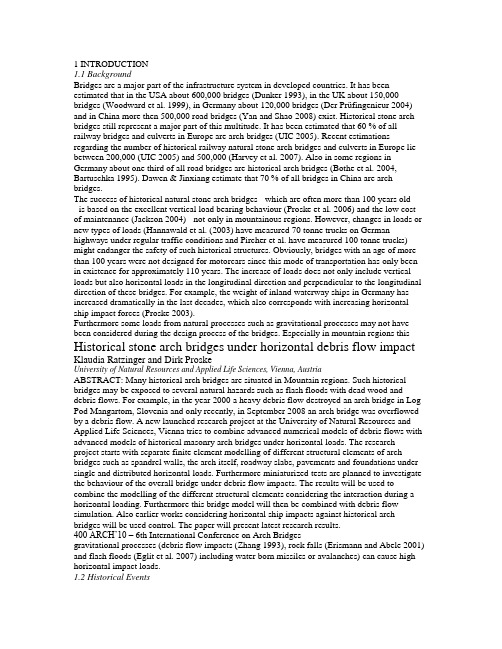
1 INTRODUCTION1.1 BackgroundBridges are a major part of the infrastructure system in developed countries. It has been estimated that in the USA about 600,000 bridges (Dunker 1993), in the UK about 150,000 bridges (Woodward et al. 1999), in Germany about 120,000 bridges (Der Prüfingenieur 2004) and in China more then 500,000 road bridges (Yan and Shao 2008) exist. Historical stone arch bridges still represent a major part of this multitude. It has been estimated that 60 % of all railway bridges and culverts in Europe are arch bridges (UIC 2005). Recent estimations regarding the number of historical railway natural stone arch bridges and culverts in Europe lie between 200,000 (UIC 2005) and 500,000 (Harvey et al. 2007). Also in some regions in Germany about one third of all road bridges are historical arch bridges (Bothe et al. 2004, Bartuschka 1995). Dawen & Jinxiang estimate that 70 % of all bridges in China are arch bridges.The success of historical natural stone arch bridges - which are often more than 100 years old- is based on the excellent vertical load bearing behaviour (Proske et al. 2006) and the low cost of maintenance (Jackson 2004) - not only in mountainous regions. However, changes in loads or new types of loads (Hannawald et al. (2003) have measured 70 tonne trucks on German highways under regular traffic conditions and Pircher et al. have measured 100 tonne trucks) might endanger the safety of such historical structures. Obviously, bridges with an age of more than 100 years were not designed for motorcars since this mode of transportation has only been in existence for approximately 110 years. The increase of loads does not only include vertical loads but also horizontal loads in the longitudinal direction and perpendicular to the longitudinal direction of these bridges. For example, the weight of inland waterway ships in Germany has increased dramatically in the last decades, which also corresponds with increasing horizontal ship impact forces (Proske 2003).Furthermore some loads from natural processes such as gravitational processes may not have been considered during the design process of the bridges. Especially in mountain regions this Historical stone arch bridges under horizontal debris flow impact Klaudia Ratzinger and Dirk ProskeUniversity of Natural Resources and Applied Life Sciences, Vienna, AustriaABSTRACT: Many historical arch bridges are situated in Mountain regions. Such historical bridges may be exposed to several natural hazards such as flash floods with dead wood and debris flows. For example, in the year 2000 a heavy debris flow destroyed an arch bridge in Log Pod Mangartom, Slovenia and only recently, in September 2008 an arch bridge was overflowed by a debris flow. A new launched research project at the University of Natural Resources and Applied Life Sciences, Vienna tries to combine advanced numerical models of debris flows with advanced models of historical masonry arch bridges under horizontal loads. The research project starts with separate finite element modelling of different structural elements of arch bridges such as spandrel walls, the arch itself, roadway slabs, pavements and foundations under single and distributed horizontal loads. Furthermore miniaturized tests are planned to investigate the behaviour of the overall bridge under debris flow impacts. The results will be used to combine the modelling of the different structural elements considering the interaction during a horizontal loading. Furthermore this bridge model will then be combined with debris flow simulation. Also earlier works considering horizontal ship impacts against historical arch bridges will be used control. The paper will present latest research results.400 ARCH’10 – 6th International Conference on Arch Bridgesgravitational processes (debris flow impacts (Zhang 1993), rock falls (Erismann and Abele 2001) and flash floods (Eglit et al. 2007) including water born missiles or avalanches) can cause high horizontal impact loads.1.2 Historical EventsIn the year 2000, a debris flow destroyed two bridges in Log Pod Mangartom, Slovenia, one of them was a historical arch bridge. In October 2007 the historical arch bridge in Beniarbeig, Spain was destroyed by a flash flood. Similarly the Pöppelmann arch bridge in Grimma, Germany was destroyed in 2002, in 2007 a farm track and public footpath arch bridge over the River Devon collapsed.Figure 1: Debris flow impact at the Lattenbach (Proske & Hübl, 2007)Fig.1 shows an example of the historical arch bridge at the Lattenbach, before and after a debris flow event, where the bridge is nearly completely filled with debris.Due to far too expensive solutions or not applicable methods for historical arch bridges it would be very useful if models were available to estimate the load bearing capacity of historical masonry arch bridges for horizontal loads perpendicular to the longitudinal direction.Since intensive research was carried out for the development of models dealing with vertical loads for historical arch bridges, there is an unsurprising lack of models capable for horizontal impact forces against the superstructure. This might be mainly based on the assumption that horizontal loads are not of major concern for this bridge type due to the great death load of such bridges.The goal of this investigation is the development of engineering models describing the behaviour of historical natural stone arch bridges under horizontal forces, mainly debris flow impacts, focused strongly on the behaviour of the superstructure and based on numerical simulations using discrete element models and finite element models.2 INNOVATIVE ASPECT AND GOALS2.1 Innovative AspectsThe conservation of historical arch bridges is not only an issue of the preservation of cultural heritage but is also an economic issue since the number of historical bridges in developed countries is huge (Proske 2009). Compared to vertical load cases no models currently exist for horizontal loads perpendicular to the longitudinal direction. It is therefore required to develop new models dealing with these capacious horizontal loads which include all types of gravitational hazards like avalanches, debris flow, rock falls or flood borne missiles or impacts from modes of transportation. First works related to the development of debris flow design impact forces and the behaviour of arch bridges under such an impact have started already 2007 at the Institute of Alpine Mountain Risk Engineering at the University of Natural Resources and Applied Life Sciences, Vienna (see Fig.2)Klaudia Ratzinger and Dirk Proske 401Figure 2 : Examples of the structural behaviour under impacts (left against the pier, right against the arch itself) (Proske and Hübl 2007)This investigation and its results regarding debris flow impact will flow into the development of the new Austrian code of practice Ö-Norm 24801 for the design of structures exposed to debris flow impacts as well.2.2 GoalTo develop load bearing behavior models of historical natural stone arch bridges under horizontal loads perpendicular to the longitudinal direction, a realistic model of debris flow against solid structures has to be implemented indifferent programs. Separate finite element modelling of different structural elements of arch bridges such as spandrel walls, the arch itself, roadway slabs, pavements and foundations under single and distributed horizontal loads are part of this investigation. Furthermore miniaturized tests are part of the project to investigate the behaviour of the overall bridge under debris flow impacts. The results will be used to combine the modelling of the different structural elements considering the interaction during a horizontal loading. Furthermore this bridge model will then be combined with debris flow simulation. Also earlier works considering horizontal ship impacts against historical arch bridges will be used. Therefore three models of historical arch bridges are developed:(1) Discrete element program model (PFC),(2) Explicit finite difference program model (FLAC),(3) Finite element program model (ANSYS, ATENA).The first and second models are developed to simulate an overall debris flow impact scenario, whereas the third model is used to investigate details, such as single force against a spandrel wall, single force against parapets, friction at the arch, single impact force against the arch. Results from the impact simulation against the superstructure should give an answer, whether the complete process can be separated into forces acting on the bridge. This reference force (force-time-function) will then be applied on the finite element models.The numerical modelling will be accompanied by testing to permit validation of the models. The tests will be carried out as miniaturized tests (scale about 1:20…50). Already miniaturized tests of the impact of debris flows against debris flow barriers were already carried out at the Institute of Mountain Risk Engineering (Proske et al. 2008, Hübl & Holzinger 2003,Fig.3). Based on this experience, miniaturized arch bridges (span about 40 to 50 cm) will be constructed and investigated. Also single parts of the arch structure will be investigated in testing machines, such as behaviour of a pure arch under a horizontal load. Since the machine cannot be turned, force redirection mechanisms will be used to allow the application of a standard compression test machine from the University of Natural Resources and Applied Life Sciences, Vienna.402 ARCH’10 – 6th International Conference on Arch BridgesFigure 3 : Side view and view from above of the used debris flow impact measurement test set-up (Hübl & Holzinger 2003)3 CALCULATIONS3.1 Discrete element methodsDiscrete element modeling can be done by usingPFC3D (Particle Flow Code 3D) which is used in analysis, testing and research in any field where the interaction of many discrete objects exhibiting large-strain and/or fracturing is required. By using the program PFC3D, materials can be modeled as either bonded (cemented) or granular assemblies of particle s.3.2 Finite element methodsThe finite element method (FEM) is one of the most powerful computer methods for solving partial differential equations applied on complex shapes and with complex boundary conditions.A mesh made of a complex system of points is programmed containing material and structural properties defining the reaction of the structure to certain loading conditions. Nodes are assigned at a certain density throughout the material depending on the anticipated stress levels of a certain area.Two types of analysis are commonly used: 2-D modelling and 3-D modelling. 2-D modelling allows the analysis to be run on a normal computer but tends to yield less accurate results whereas 3-D modelling shows more accurate results.For this investigation two FEM programs are used:(1) ANSYS(2) ATENAANSYS is the leading finite element analysis package for numerically solving a wide varietyof mechanical problems in 2D and 3D. By using ANSYS, the analysis can be done linear and non-linear, is applicable to static and dynamic structural analysis, heat transfer and fluid problems as well as acoustic and electromagnetic problems.The ATENA program is determined for nonlinear finite element analysis of structures, offers tools specially designed for computer simulation of concrete and reinforced concrete structural behaviour. Moreover, structures from other materials, such as soils, metals etc. can be treated as well.In the first step finite element methods are used to simulate the behaviour of historical natural stone arch bridges under an impact. Required data for the debris flow models are taken from the database of the Institute of Mountain Risk Engineering as well from the Austrian RailwayService (ÖBB).Klaudia Ratzinger and Dirk Proske 403The basic requirements for an appropriate assessment of stone arch bridges are:(1) Choice of a realistic calculation model(2) Consideration of geometrical and material nonlinearities(3) Using applicable material models for masonry(4) Adapted evidence based on the chosen material models.Therefore, a simplified arch bridge model with various lengths (L), rising of the vault (r) and thickness of the stone arch (t) was chosen (Fig.4) – first by using a two-dimensional model –with the purpose to investigate the importance of geometrical properties to their structural performance and to demonstrate different results. Further models are in process and will be implemented in the FEM programs as well.Figure 4 : FE model of a simplified arch bridge (Becke, 2005)4 CONCLUSIONSThis research project launched by the University of Natural Resources and Applied Life Sciences, Vienna combines advanced numerical models of debris flows with advanced models of historical masonry arch bridges under horizontal loads. It started with the implementation of separate finite element modelling of different structural elements of arch bridges. Furthermore miniaturized tests will be done in 2010 to investigate the behaviour of the overall bridge under debris flow impacts. The results will be used to combine the modelling of the different structural elements considering the interaction during a horizontal loading and the bridge model will be combined with debris flow simulation.Last but not least recommendation values for such bridge types should be given by this investigation that may include further formulas considering for example the adaptation of masonry stiffness or strength values.1介绍1.1背景桥梁是发达国家的基础设施系统的一个主要部分。
桥梁工程毕业设计外文翻译(箱梁)

西南交通大学本科毕业设计(论文)外文资料翻译年级:学号:姓名:专业:指导老师:2013年 6 月外文资料原文:13Box girders13.1 GeneralThe box girder is the most flexible bridge deck form。
It can cover a range of spans from25 m up to the largest non—suspended concrete decks built, of the order of 300 m。
Single box girders may also carry decks up to 30 m wide。
For the longer span beams, beyond about 50 m,they are practically the only feasible deck section. For the shorter spans they are in competition with most of the other deck types discussed in this book.The advantages of the box form are principally its high structural efficiency (5.4),which minimises the prestress force required to resist a given bending moment,and its great torsional strength with the capacity this gives to re—centre eccentric live loads,minimising the prestress required to carry them。
The box form lends itself to many of the highly productive methods of bridge construction that have been progressively refined over the last 50 years,such as precast segmental construction with or without epoxy resin in the joints,balanced cantilever erection either cast in—situ or coupled with precast segmental construction, and incremental launching (Chapter 15)。
建筑土木工程外文翻译外文文献英文文献混凝土桥梁
建筑土木工程外文翻译外文文献英文文献混凝土桥梁Concrete BridgesConcrete is the most-used construction material for bridges in the United States, and indeed in the world. The application of prestressing to bridges has grown rapidly and steadily, beginning in 1949 with high-strength steel wires in the Walnut Lane Bridge in Philadelphia, Pennsylvania. According to the Federal Highway Administration’s 1994 National Bridge Inventory data, from 1950 to the early 1990s, prestressed concrete bridges have gone from being virtually nonexistent to representing over 50 percent of all bridges built in the United States.Prestressing has also played an important role in extending the span capability of concrete bridges. By the late 1990s, spliced-girder spans reached a record 100 m (330 ft). Construction of segmental concrete bridges began in the United States in 1974.Curretly, close to 200 segmental concrete bridges have been built or are under construction, with spans up to 240 m (800 ft).Late in the 1970s, cable-stayed construction raised the bar for concrete bridges. By 1982, the Sunshine Skyway Bridge in Tampa, Florida, had set a new record for concrete bridges, with a main span of 365 m (1,200 ft). The next year, the Dames Point Bridge in Jacksonville, Florida, extended the record to 400 m (1,300 ft).HIGH-PERFORMANCE CONCRETECompressive StrengthFor many years the design of precast prestressed concrete girders was based on concrete compressive strengths of 34 to 41 MPa (5,000 to 6,000 psi). This strength level served the industrywell and provided the basis for establishing the prestressed concrete bridge industry in the United States. In the 1990s the industry began to utilize higher concrete compressive strengths in design, and at the start of the new millennium the industry is poised to accept the use of concrete compressive strengths up to 70 MPa (10,000 psi).For the future, the industry needs to seek ways to effectively utilize even higher concrete compressive strengths. The ready-mixed concrete industry has been producing concretes with compressive strengths in excess of 70 MPa for over 20 years. Several demonstration projects have illustrated that strengths above 70 MPa can be achieved for prestressed concrete girders. Barriers need to be removed to allow the greater use of these materials. At the same time, owners, designers, contractors, and fabricators need to be more receptive to the use of higher-compressive-strength concretes.DurabilityHigh-performance concrete (HPC) can be specified as high compressive strength (e.g., in prestressed girders) or as conventional compressive strength with improved durability (e.g., in cast-in-place bridge decks and substructures). There is a need to develop a better understanding of all the parameters that affect durability, such asresistance to chemical, electrochemical, and environmental mechanisms that attack the integrity of the material. Significant differences might occur in the long-term durability of adjacent twin structures constructed at the same time using identical materials. This reveals our lack of understanding and control of the parameters that affect durability. NEW MATERIALS Concrete design specifications have in the past focusedprimarily on the compressive strength. Concrete is slowly moving toward an engineered material whose direct performance can be altered by the designer. Material properties such as permeability, ductility, freeze-thaw resistance, durability, abrasion resistance, reactivity, and strength will be specified. The HPC initiative has gone a long way in promoting these specifications, but much more can be done. Additives, such a fibers or chemicals, can significantly alter the basic properties of concrete. Other new materials, such as fiber-reinforced polymer composites, nonmetallic reinforcement (glass fiber-reinforced and carbon fiber-reinforced plastic, etc.), new metallic reinforcements, or high-strength steel reinforcement can also be used to enhance the performance of what is considered to be a traditional material. Higher-strength reinforcement could be particularly useful when coupled with high-strength concrete. As our natural resources diminish, alternative aggregate sources (e.g., recycled aggregate) and further replacement of cementitious materials with recycled products are being examined. Highly reactive cements and reactive aggregates will be concerns of the past as new materials with long-term durability become commonplace.New materials will also find increasing demand in repair and retrofitting. As the bridge inventory continues to get older, increasing the usable life of structures will become critical. Some innovative materials, although not economical for complete bridges, will find their niche in retrofit and repair.OPTIMIZED SECTIONSIn early applications of prestressed concrete to bridges, designers developed their own ideas of the best girder sections. The result is that each contractor used slightly different girder shapes. It was too expensive to design custom girders for eachproject.As a result, representatives for the Bureau of Public Roads (now FHWA), the American Association of State Highway Officials (AASHO) (now AASHTO), and the Prestressed Concrete Institute (PCI) began work to standardize bridge girder sections. The AASHTO-PCI standard girder sections Types I through IV were developed in the late 1950s and Types V and VI in the early 1960s. There is no doubt that standardization of girders has simplified design, has led to wider utilization of prestressed concrete for bridges, and, more importantly, has led to reduction in cost.With advancements in the technology of prestressed concrete design and construction, numerous states started to refine their designs and to develop their own standard sections. As a result, in the late 1970s, FHWA sponsored a study to evaluate existing standard girder sections and determine the most efficient girders. This study concluded that bulb-tees were the most efficient sections. These sections could lead to reduction in girder weights of up to 35 percent compared with the AASHTO Type VI and cost savings up to 17 percent compared with the AASHTO-PCI girders, for equal spancapability. On the basis of the FHWA study, PCI developed the PCI bulb-tee standard, which was endorsed by bridge engineers at the 1987 AASHTO annual meeting. Subsequently, the PCI bulb-tee cross section was adopted in several states. In addition, similar cross sections were developed and adopted in Florida, Nebraska, and the New England states. These cross sections are also cost-effective with high-strength concretes for span lengths up to about 60 m (200 ft).SPLICED GIRDERSSpliced concrete I-girder bridges are cost-effective for a spanrange of 35 to 90 m (120 to 300 ft). Other shapes besides I-girders include U, T, and rectangular girders, although the dominant shape in applications to date has been the I-girder, primarily because of its relatively low cost. A feature of spliced bridges is the flexibility they provide in selection of span length, number and locations of piers, segment lengths, and splice locations. Spliced girders have the ability to adapt to curved superstructure alignments by utilizing short segment lengths and accommodating the change in direction in the cast-in-place joints. Continuity in spliced girder bridges can be achieved through full-length posttensioning, conventional reinforcement in the deck, high-strength threaded bar splicing, or pretensioned strand splicing, although the great majority of applications utilize full-length posttensioning. The availability of concrete compressive strengths higher than the traditional 34 MPa (5,000 psi) significantly improves the economy of spliced girder designs, in which high flexural and shear stresses are concentrated near the piers. Development of standardized haunched girder pier segments is needed for efficiency in negative-moment zones. Currently, the segment shapes vary from a gradually thickening bottom flange to a curved haunch with constant-sized bottom flange and variable web depth.SEGMENTAL BRIDGESSegmental concrete bridges have become an established type of construction for highway and transit projects on constrained sites. Typical applications include transit systems over existing urban streets and highways, reconstruction of existing interchanges and bridges under traffic, or projects that cross environmentally sensitive sites. In addition, segmental construction has been proved to be appropriate for large-scale,repetitive bridges such as long waterway crossings or urban freeway viaducts or where the aesthetics of the project are particularly important.Current developments suggest that segmental construction will be used on a larger number of projects in the future. Standard cross sections have been developed to allow for wider application of this construction method to smaller-scale projects. Surveys of existing segmental bridges have demonstrated the durability of this structure type and suggest that additional increases in design life are possible with the use of HPC. Segmental bridges with concrete strengths of 55 MPa (8,000 psi) or more have been constructed over the past 5 years. Erection with overhead equipment has extended applications to more congested urban areas. Use of prestressed composite steel and concrete in bridges reduces the dead weight of the superstructure and offers increased span lengths.LOAD RATING OF EXISTING BRIDGESExisting bridges are currently evaluated by maintaining agencies using working stress, load factor, or load testing methods. Each method gives different results, for several reasons. In order to get national consistency, FHWA requests that all states report bridge ratings using the load factor method. However, the new AASHTO Load and Resistance Factor Design (LRFD) bridge design specifications are different from load factor method. A discrepancy exists, therefore, between bridge design and bridge rating.A draft of a manual on condition evaluation of bridges, currently under development for AASHTO, has specifications for load and resistance factor rating of bridges. These specifications represent a significant change from existing ones. States will beasked to compare current load ratings with the LRFD load ratings using a sampling of bridges over the next year, and adjustments will be proposed. The revised specifications and corresponding evaluation guidelines should complete the LRFD cycle of design, construction, and evaluation for the nation's bridges.LIFE-CYCLE COST ANALYSISThe goal of design and management of highway bridges is to determine and implement the best possible strategy that ensures an adequate level of reliability at the lowest possible life-cycle cost. Several recent regulatory requirements call for consideration of life-cycle cost analysis for bridge infrastructure investments. Thus far, however, the integration of life-cycle cost analysis with structural reliability analysis has been limited. There is no accepted methodology for developing criteria for life-cycle cost design and analysis of new and existing bridges. Issues such as target reliability level, whole-life performance assessment rules, and optimum inspection-repair-replacement strategies for bridges must be analyzed and resolved from a life-cycle cost perspective. T o achieve this design and management goal, state departments of transportation must begin to collect the data needed to determine bridge life-cycle costs in a systematic manner. The data must include inspection, maintenance, repair, and rehabilitation expenditures and the timing of these expenditures. At present, selected state departments of transportation are considering life-cycle cost methodologies and software with the goal of developing a standard method for assessing the cost-effectiveness of concrete bridges. DECKS Cast-in-place (CIP) deck slabs are the predominant method of deck construction in the United States. Their main advantage is the ability to provide a smooth riding surface by field-adjustment of the roadway profile during concrete placement. In recent years automation of concrete placement and finishing has made this system cost-effective. However, CIP slabs have disadvantages that include excessive differential shrinkage with the supporting beams and slow construction. Recent innovations in bridge decks have focused on improvement to current practice with CIP decks and development of alternative systems that are cost-competitive, fast to construct, and durable. Focus has been on developing mixes and curing methods that produce performance characteristics such as freeze-thaw resistance, high abrasion resistance, low stiffness, and low shrinkage, rather than high strength. Full-depth precast panels have the advantages of significant reduction of shrinkage effects and increased construction speed and have been used in states with high traffic volumes for deck replacement projects. NCHRP Report 407 on rapid replacement of bridge decks has provided a proposed full-depth panel system with panels pretensioned in the transverse direction and posttensioned in the longitudinaldirection.Several states use stay-in-place (SIP) precast prestressed panels combined with CIP topping for new structures as well as for deck replacement. This system is cost-competitive with CIP decks. The SIP panels act as forms for the topping concrete and also as part of the structural depth of the deck. This system can significantly reduce construction time because field forming is only needed for the exterior girder overhangs. The SIP panel system suffers from reflective cracking, which commonly appears over the panel-to-panel joints. A modified SIP precast panel system has recently been developed in NCHRP Project 12-41.SUBSTRUCTURESContinuity has increasingly been used for precast concrete bridges. For bridges with total lengths less than 300 m (1,000 ft), integral bridge abutments and integral diaphragms at piers allow for simplicity in construction and eliminate the need for maintenance-prone expansion joints. Although the majority of bridge substructure components continue to be constructed from reinforced concrete, prestressing has been increasingly used. Prestressed bents allow for longer spans, improving durability and aesthetics and reducing conflicts with streets and utilities in urban areas. Prestressed concrete bents are also being used for structural steel bridges to reduce the overall structure depth and increase vertical clearance under bridges. Precast construction has been increasingly used for concrete bridge substructure components. Segmental hollow box piers and precast pier caps allow for rapid construction and reduced dead loads on the foundations. Precasting also enables the use of more complex forms and textures in substructure components, improving the aesthetics of bridges in urban and rural areas. RETAINING WALLSThe design of earth retaining structures has changed dramatically during the last century. Retaining wall design has evolved from short stone gravity sections to concrete structures integrating new materials such as geosynthetic soil reinforcements and high-strength tie-back soil anchors.The design of retaining structures has evolved into three distinct areas. The first is the traditional gravity design using the mass of the soil and the wall to resist sliding and overturning forces. The second is referred to as mechanically stabilized earth design. This method uses the backfill soil exclusively as the mass to resist the soil forces by engaging the soil using steel orpolymeric soil reinforcements. A third design method is the tie-back soil or rock anchor design, which uses discrete high-strength rods or cables that are drilled deep into the soil behind the wall to provide a dead anchorage to resist the soil forces.A major advancement in the evolution of earth retaining structures has been the proliferation of innovative proprietary retaining walls. Many companies have developed modular wall designs that are highly adaptable to many design scenarios. The innovative designs combined with the modular standard sections and panels have led to a significant decrease in the cost for retaining walls. Much research has been done to verify the structural integrity of these systems, and many states have embraced these technologies. RESEARCHThe primary objectives for concrete bridge research in the 21st century are to develop and test new materials that will enable lighter, longer, more economical, and more durable concrete bridge structures and to transfer this technology into the hands of the bridge designers for application. The HPCs developed toward the end of the 20th century would be enhanced by development of more durable reinforcement. In addition, higher-strength prestressing reinforcement could more effectively utilize the achievable higher concrete strengths. Lower-relaxation steel could benefit anchor zones. Also, posttensioning tendons and cable-stays could be better designed for eventual repair and replacement. As our natural resources diminish, the investigation of the use of recycled materials is as important as the research on new materials.The development of more efficient structural sections to better utilize the performance characteristics of new materials is important. In addition, more research is required in the areas ofdeck replacement panels, continuity regions of spliced girder sections, and safe,durable, cost-effective retaining wall structures.Research in the areas of design and evaluation will continue into the next millennium.The use of HPC will be facilitated by the removal of the implied strength limitation of 70 MPa (10.0 ksi) and other barriers in the LRFD bridge design specifications. As our nation’s infrastructure continues to age and as the vehicle loads continue to increase, it is important to better evaluate the capacity of existing structures and to develop effective retrofitting techniques. Improved quantification of bridge system reliability is expected through the calibration of system factors to assess the member capacities as a function of the level of redundancy. Data regarding inspection, maintenance, repair, and rehabilitation expenditures and their timing must be systematically collected and evaluated to develop better methods of assessing cost-effectiveness of concrete bridges. Performance-based seismic design methods will require a higher level of computing and better analysis tools.In both new and existing structures, it is important to be able to monitor the “health” of these structures through the development of instrumentation (e.g., fiber optics) to determine the state of stresses and corrosion in the members.CONCLUSIONIntroduced into the United States in 1949, prestressed concrete bridges today represent over 50 percent of all bridges built. This increase has resulted from advancements in design and analysis procedures and the development of new bridge systems and improved materials.The year 2000 sets the stage for even greater advancements. An exciting future lies ahead for concrete bridges!混凝土桥梁在美国甚至在世界桥梁上,混凝土是最常用的建设材料。
道路与桥梁工程中英文对照外文翻译文献

中英文对照外文翻译(文档含英文原文和中文翻译)Bridge research in EuropeA brief outline is given of the development of the European Union, together with the research platform in Europe. The special case of post-tensioned bridges in the UK is discussed. In order to illustrate the type of European research being undertaken, an example is given from the University of Edinburgh portfolio: relating to the identification of voids in post-tensioned concrete bridges using digital impulse radar.IntroductionThe challenge in any research arena is to harness the findings of different research groups to identify a coherent mass of data, which enables research and practice to be better focused. A particular challenge exists with respect to Europe where language barriers are inevitably very significant. The European Community was formed in the 1960s based upon a political will within continental Europe to avoid the European civil wars, which developed into World War 2 from 1939 to 1945. The strong political motivation formed the original community of which Britain was not a member. Many of the continental countries saw Britain’s interest as being purelyeconomic. The 1970s saw Britain joining what was then the European Economic Community (EEC) and the 1990s has seen the widening of the community to a European Union, EU, with certain political goals together with the objective of a common European currency.Notwithstanding these financial and political developments, civil engineering and bridge engineering in particular have found great difficulty in forming any kind of common thread. Indeed the educational systems for University training are quite different between Britain and the European continental countries. The formation of the EU funding schemes —e.g. Socrates, Brite Euram and other programs have helped significantly. The Socrates scheme is based upon the exchange of students between Universities in different member states. The Brite Euram scheme has involved technical research grants given to consortia of academics and industrial partners within a number of the states— a Brite Euram bid would normally be led by an industrialist.In terms of dissemination of knowledge, two quite different strands appear to have emerged. The UK and the USA have concentrated primarily upon disseminating basic research in refereed journal publications: ASCE, ICE and other journals. Whereas the continental Europeans have frequently disseminated basic research at conferences where the circulation of the proceedings is restricted.Additionally, language barriers have proved to be very difficult to break down. In countries where English is a strong second language there has been enthusiastic participation in international conferences based within continental Europe —e.g. Germany, Italy, Belgium, The Netherlands and Switzerland. However, countries where English is not a strong second language have been hesitant participants }—e.g. France.European researchExamples of research relating to bridges in Europe can be divided into three types of structure:Masonry arch bridgesBritain has the largest stock of masonry arch bridges. In certain regions of the UK up to 60% of the road bridges are historic stone masonry arch bridges originally constructed for horse drawn traffic. This is less common in other parts of Europe as many of these bridges were destroyed during World War 2.Concrete bridgesA large stock of concrete bridges was constructed during the 1950s, 1960s and 1970s. At the time, these structures were seen as maintenance free. Europe also has a large number of post-tensioned concrete bridges with steel tendon ducts preventing radar inspection. This is a particular problem in France and the UK.Steel bridgesSteel bridges went out of fashion in the UK due to their need for maintenance as perceived in the 1960s and 1970s. However, they have been used for long span and rail bridges, and they are now returning to fashion for motorway widening schemes in the UK.Research activity in EuropeIt gives an indication certain areas of expertise and work being undertaken in Europe, but is by no means exhaustive.In order to illustrate the type of European research being undertaken, an example is given from the University of Edinburgh portfolio. The example relates to the identification of voids in post-tensioned concrete bridges, using digital impulse radar.Post-tensioned concrete rail bridge analysisOve Arup and Partners carried out an inspection and assessment of the superstructure of a 160 m long post-tensioned, segmental railway bridge in Manchester to determine its load-carrying capacity prior to a transfer of ownership, for use in the Metrolink light rail system..Particular attention was paid to the integrity of its post-tensioned steel elements. Physical inspection, non-destructive radar testing and other exploratory methods were used to investigate for possible weaknesses in the bridge.Since the sudden collapse of Ynys-y-Gwas Bridge in Wales, UK in 1985, there has been concern about the long-term integrity of segmental, post-tensioned concrete bridges which may b e prone to ‘brittle’ failure without warning. The corrosion protection of the post-tensioned steel cables, where they pass through joints between the segments, has been identified as a major factor affecting the long-term durability and consequent strength of this type of bridge. The identification of voids in grouted tendon ducts at vulnerable positions is recognized as an important step in the detection of such corrosion.Description of bridgeGeneral arrangementBesses o’ th’ Barn Bridge is a 160 m long, three span, segmental, post-tensionedconcrete railway bridge built in 1969. The main span of 90 m crosses over both the M62 motorway and A665 Bury to Prestwick Road. Minimum headroom is 5.18 m from the A665 and the M62 is cleared by approx 12.5 m.The superstructure consists of a central hollow trapezoidal concrete box section 6.7 m high and 4 m wide. The majority of the south and central spans are constructed using 1.27 m long pre-cast concrete trapezoidal box units, post-tensioned together. This box section supports the in site concrete transverse cantilever slabs at bottom flange level, which carry the rail tracks and ballast.The center and south span sections are of post-tensioned construction. These post-tensioned sections have five types of pre-stressing:1. Longitudinal tendons in grouted ducts within the top and bottom flanges.2. Longitudinal internal draped tendons located alongside the webs. These are deflected at internal diaphragm positions and are encased in in site concrete.3. Longitudinal macalloy bars in the transverse cantilever slabs in the central span .4. Vertical macalloy bars in the 229 mm wide webs to enhance shear capacity.5. Transverse macalloy bars through the bottom flange to support the transverse cantilever slabs.Segmental constructionThe pre-cast segmental system of construction used for the south and center span sections was an alternative method proposed by the contractor. Current thinking suggests that such a form of construction can lead to ‘brittle’ failure of the ent ire structure without warning due to corrosion of tendons across a construction joint,The original design concept had been for in site concrete construction.Inspection and assessmentInspectionInspection work was undertaken in a number of phases and was linked with the testing required for the structure. The initial inspections recorded a number of visible problems including:Defective waterproofing on the exposed surface of the top flange.Water trapped in the internal space of the hollow box with depths up to 300 mm.Various drainage problems at joints and abutments.Longitudinal cracking of the exposed soffit of the central span.Longitudinal cracking on sides of the top flange of the pre-stressed sections.Widespread sapling on some in site concrete surfaces with exposed rusting reinforcement.AssessmentThe subject of an earlier paper, the objectives of the assessment were:Estimate the present load-carrying capacity.Identify any structural deficiencies in the original design.Determine reasons for existing problems identified by the inspection.Conclusion to the inspection and assessmentFollowing the inspection and the analytical assessment one major element of doubt still existed. This concerned the condition of the embedded pre-stressing wires, strands, cables or bars. For the purpose of structural analysis these elements、had been assumed to be sound. However, due to the very high forces involved,、a risk to the structure, caused by corrosion to these primary elements, was identified.The initial recommendations which completed the first phase of the assessment were:1. Carry out detailed material testing to determine the condition of hidden structural elements, in particularthe grouted post-tensioned steel cables.2. Conduct concrete durability tests.3. Undertake repairs to defective waterproofing and surface defects in concrete.Testing proceduresNon-destructi v e radar testingDuring the first phase investigation at a joint between pre-cast deck segments the observation of a void in a post-tensioned cable duct gave rise to serious concern about corrosion and the integrity of the pre-stress. However, the extent of this problem was extremely difficult to determine. The bridge contains 93 joints with an average of 24 cables passing through each joint, i.e. there were approx. 2200 positions where investigations could be carried out. A typical section through such a joint is that the 24 draped tendons within the spine did not give rise to concern because these were protected by in site concrete poured without joints after the cables had been stressed.As it was clearly impractical to consider physically exposing all tendon/joint intersections, radar was used to investigate a large numbers of tendons and hence locate duct voids within a modest timescale. It was fortunate that the corrugated steel ducts around the tendons were discontinuous through the joints which allowed theradar to detect the tendons and voids. The problem, however, was still highly complex due to the high density of other steel elements which could interfere with the radar signals and the fact that the area of interest was at most 102 mm wide and embedded between 150 mm and 800 mm deep in thick concrete slabs.Trial radar investigations.Three companies were invited to visit the bridge and conduct a trial investigation. One company decided not to proceed. The remaining two were given 2 weeks to mobilize, test and report. Their results were then compared with physical explorations.To make the comparisons, observation holes were drilled vertically downwards into the ducts at a selection of 10 locations which included several where voids were predicted and several where the ducts were predicted to be fully grouted. A 25-mm diameter hole was required in order to facilitate use of the chosen horoscope. The results from the University of Edinburgh yielded an accuracy of around 60%.Main radar sur v ey, horoscope verification of v oids.Having completed a radar survey of the total structure, a baroscopic was then used to investigate all predicted voids and in more than 60% of cases this gave a clear confirmation of the radar findings. In several other cases some evidence of honeycombing in the in site stitch concrete above the duct was found.When viewing voids through the baroscopic, however, it proved impossible to determine their actual size or how far they extended along the tendon ducts although they only appeared to occupy less than the top 25% of the duct diameter. Most of these voids, in fact, were smaller than the diameter of the flexible baroscopic being used (approximately 9 mm) and were seen between the horizontal top surface of the grout and the curved upper limit of the duct. In a very few cases the tops of the pre-stressing strands were visible above the grout but no sign of any trapped water was seen. It was not possible, using the baroscopic, to see whether those cables were corroded.Digital radar testingThe test method involved exciting the joints using radio frequency radar antenna: 1 GHz, 900 MHz and 500 MHz. The highest frequency gives the highest resolution but has shallow depth penetration in the concrete. The lowest frequency gives the greatest depth penetration but yields lower resolution.The data collected on the radar sweeps were recorded on a GSSI SIR System 10.This system involves radar pulsing and recording. The data from the antenna is transformed from an analogue signal to a digital signal using a 16-bit analogue digital converter giving a very high resolution for subsequent data processing. The data is displayed on site on a high-resolution color monitor. Following visual inspection it is then stored digitally on a 2.3-gigabyte tape for subsequent analysis and signal processing. The tape first of all records a ‘header’ noting the digital radar settings together with the trace number prior to recording the actual data. When the data is played back, one is able to clearly identify all the relevant settings —making for accurate and reliable data reproduction.At particular locations along the traces, the trace was marked using a marker switch on the recording unit or the antenna.All the digital records were subsequently downloaded at the University’s NDT laboratory on to a micro-computer.(The raw data prior to processing consumed 35 megabytes of digital data.)Post-processing was undertaken using sophisticated signal processing software. Techniques available for the analysis include changing the color transform and changing the scales from linear to a skewed distribution in order to highlight、突出certain features. Also, the color transforms could be changed to highlight phase changes. In addition to these color transform facilities, sophisticated horizontal and vertical filtering procedures are available. Using a large screen monitor it is possible to display in split screens the raw data and the transformed processed data. Thus one is able to get an accurate indication of the processing which has taken place. The computer screen displays the time domain calibrations of the reflected signals on the vertical axis.A further facility of the software was the ability to display the individual radar pulses as time domain wiggle plots. This was a particularly valuable feature when looking at individual records in the vicinity of the tendons.Interpretation of findingsA full analysis of findings is given elsewhere, Essentially the digitized radar plots were transformed to color line scans and where double phase shifts were identified in the joints, then voiding was diagnosed.Conclusions1. An outline of the bridge research platform in Europe is given.2. The use of impulse radar has contributed considerably to the level of confidence in the assessment of the Besses o’ th’ Barn Rail Bridge.3. The radar investigations revealed extensive voiding within the post-tensioned cable ducts. However, no sign of corrosion on the stressing wires had been found except for the very first investigation.欧洲桥梁研究欧洲联盟共同的研究平台诞生于欧洲联盟。
桥梁专业外文翻译现代桥梁美学的发展空间
Expressing space force system and inheriting humanism —The Space For Modern Bridge Aesthetics DevelopmentPan FangAbstract The harmony of mechanics and aesthetics is the logical basis for the existence and the development of bridge aesthetics. When force-bearing properties of space force system are woven into bridge design, the spirits of sculpture are instilled into bridge structures. And the intervention of the tradition of humanities converts bridges into spatial-temporal sequences that embody local conventional character and recur to bridges’genius loci. The combination of both provides many alternatives of the development of modern bridge aesthetics.Keywords space force system the tradition of humanities bridge aesthetics“We think our civilization near its meridian,but we are yet only at the cock-crowing and the morning star.”----Emerson, RalphWaldo1. Present statusNowadays, there are two mainstreams in bridges development. One is the trend of extra long-span bridges, and another is the urbanization of middle-span or small-span bridges. These two trends exactly correspond to two features of bridges.The first one is the cultural function of bridge serving as a symbol of critic or national character additional to its conventional function to support loads .The giant exposed elements of bridges inherently embody human’s strength, courage and will toconquer the river. And this is especially true in extra long-span bridges .Another obvious character of bridge is that it enables people to occupy the space owned by river. As a result ,on one hand, human attaches to the space where he originally belongs to, on the other hand he can move back and forth between banks. That makes him feel simultaneously interior and exterior, openness, freedom and protection. This experience of passengers comes through the stream of complex interplay of structure itself and its surroundings.Up to now, experience accumulated on space force systems guarantees the credibility of such complex structures as cable-arch structures and bridges subjected to gale. And advanced computer-aided design facilitates visualization of three-dimensional model of the structure under discussion. Technological restrains is loosening. At the same time, bridge aesthetics begin to thrive .Genius loci, namely, spirits of place, are desired, which are deeply rooted in the tradition of humanities. Different connects are well arranged to display a spatial-temporal sequences which arouse resonance of visitors.The maturity of bridge design technique and the emphasis on humanism and tradition are prerequisites of progress of bridge aesthetics.2. Potential space latent in space force systemTheoretical supportAdmittedly, conventional procedures for bridge design have a deep influence on bridge aesthetics. Because the loads on bridges are more complex than that on buildings, in the concept design stage, architecture is involved much less. And before the introduction of computer-aided design software, almost all bridges were simplified intotwo-dimension structures in order to avoid the solution of large scale linear programming. Unfortunately, this artifice has its side-effect. It neglects bridge is a structure of three-dimension who has abundant expressive forces. Consequently, the similarity between different bridges and the stiffness in their appearance occur.Then how to elicit the vigor inside bridges when we are liberated form calculation to some extent? Reverting to bridges’ original nature of a giant sculpture is an optimal choice. As a three-dimension structure, bridge demands designers not only mentally to visualize a complex form from all round itself, to identify its centre of gravity, its mass, its weight, to realize its volume, as the space that the shape displaces in the air, but also the accurate expression of the internal ways to transfer loads, where lies the difference between bridges and common sculptures. The critical step is weaving invisible load paths into the nature of bridge mold. The example below illustrates that.The oneness of aesthetics and mechanics is the logical basis for the concept advocated above. For designers, the work doesn’t rest on that primary level. Familiarity with the behavior of space force system is desired, which includes static loads distribution, structural dynamic response to winds, waves, and cozy extent for passengers.Different results come out when bridges mainy resist different loads. If bridge is mainly subjected to static loads, for an instance, the structure weight, spectators passing through it will perceive the power and the frozen movement of it. And if dynamic, for example, wind, the security springs from bridge’s protection.Analysis of examples2.2.1 Cable-arch structureCampo V olantin Footbridge, across River Nervion, in Bilbao, Spain, tells an exact story of how a leaning arch keeps stable in the weave of cables. The construction system is a steel inclined parabolic arch with glass decking. The tortuous deck of the single-spanned footbridge is suspended on the leaning arch, and the very warp echoes to the stream of visitors from lower reaches of the river. Balance is achieved by properly setting leaning arch, which sustains most of the loads, and the horizontal curving deck. The arch is across the footpath, structurally supported by scattered cables, and at the same time, main beam is simplified into a steel well-proportioned shows.The record of design’s evolutionshowed how the typical arch is graduallyweakened, and the geometrical formbecome more and more complex, whichemphasize the impression of movement.Along the interior side of its curving deck,there is a series of low weight cables, eachof which links the arch and horizontaldeck, weaving a beautiful curve by gradually changing the very angle. In a vertical plane, all cables extend outward, whose imaginary focus alludes a rotary trend different from the axis of the steel arch. The forces generate a curve at the top of arch. Additionally, straight side of arch and cables converging in the middle of the arch form a peculiar combination ultimately. The piers not only transfer the concentrated loads to the ground equably but also serve as circumscription between the location and the abstract space occupied by bridge itself.An apparent disequilibrium or rather a sense of frozen movement is heightened by the lightness of the structure. Scattered sunlight of Basque casts continuously varied shadow on these neat compressed bars, achieving dramatic effect.2.2.2 TrussAnother representative is Wettstein Bridge across Rhine, in Basel, Switzerland. The main arches secedes other auxiliary elements to express separately, who sustain the all weight of bridge. The oblique truss arch dramatically eliminates both its own weight and the ponderosity of profile. It does reach one milestone of creating the opportunity to install thinner across section. In order to distribute the concentrated load into the side-push load pathand to strengthen the compressedarch, it is of structuralimportance to reinforce thelongitudinal stiffness. Thisdesired stiffness is provided by apair of tetrahedrons, whose lowerchords, constituting an even curve, properly serve as foil to the outline of main arch. As a whole, the details of this bridge explain more on how loads are transferred through nodes and how nodes influence stress shows.This design embodies a typical bridge aesthetic style of middle Europe. The bridge towers, the classical basic proportion and the details of steel structure all remind people of the ancient bridges in Vienna or Paris.2.2.3 Slope and curved bridgeThe giant volume ofKumamoto Bridge connects threeislands of Amakusa-shoto in theSouth Japan. Fishery has a longhistory, which creates aharmonious relationship between local inhabitants and natural environment. So this emotional need must be properly responded to. The curved line can meets this demand, but it will generate a rotary trend of movement. As an important connect among three islands, the higher traffic capacity is a vital factor. What’s more,gale often appears in beachfront, which should be considered along with the expected traffic flow.The ultimate design is a slope and curved bridge with repetitive steel box section. The outlook is like a huge arch, which curves, contorts, and ascends. At the first glance, its appearance doesn’t measure up to the curve style highway engineers are used to, which is imposed on natural topography and results in discordance with surroundings in many American freeways executed. Fortunately, Kumamoto Bridge blends well with its location and echoes to the islands it connects in space. And the simplicity in both structure and appearance resists the danger to become a daredevil manmade structure or to exaggeratedly express its show.Full-depth box section isgood at being contorted, andhence it can resist the rotarytrend of movement of thehuge prominent curve. Theconcave defense boards are setalong the edge of deck. They have been adjusted according to wind tunnel results to make pavement and bikeway are in area where airflow stands almost still. Thus it protects passengers from the gale. Wind tunnel experiments are also used to improve section shape. The optimal curved surface of bottom is chosen in order to smooth airflow and consequently improve theefficiency of the contorted box.The arrangement of suspending light-weight elements over large-scale structures reminds people of Japanese architectures in early stage, which use large block of stones as foundations and comparatively light timbers for superstructures. The piers are prisms with right angles, which add solemnity to the bridge and intensively contrast to gentle curved bottom. The steel beam is sustained on the spherical pillars, which activize strong vision impact. This curved surface also reflects changing light on water surface, generating an elegant optical illusion. At night, light hidden under the bridge bottom draws a graceful arch over the bay.space latent in humanismTheoretical supportOur ancestors viewed bridges as divine places, while in middle ages, bridges were treated as human-oriented places. Both kept a better-balanced relationship between new bridges and humanism. However, with the increasing traffic demands, this balance is undermined when the Dabby Time came, whose ultimate goal was designing rapid passageways for automobiles. As a result, the cultural function of bridge has been deserted.Apparently, such bridges contribute much to modern industrial civilization, but nothing to the history of bridge aesthetics. Bridges lost their affinity, and the sites lost their spirits of place. So rehabilitating genius loci is a necessary step to continue the hampered bridge aesthetics. Every place has its invisible, ever-transforming and yet decidedly obvious characteristic, which has been formed through the stream of a complex interplay of past and future events–all that evolved and developed there since the earth began in interplay with the ideas of those who transformed the land in the past and those who have intentions to change it in the future. Any bridge should comply with these characteristics, which are both the restrictions and qualifications for design.There is no abyss and barrier between modern civilization and the tradition of humanities. On the contrary, this tradition is the soil filled with experience, inspiration, and nutrition where modern civilization roots in. No matter how old the aestheticreferences are, modern techniques can be a proper receptacle to convey its nature. Analysis of exampleMiho Museum Footbridge is a concrete example, which is one of typical representatives of BeiYuming. Miho Museum is hidden in the Shigaraki craggyterrain; hence a special inlet is desired.In his design, a sinuous trace paves the way to a narrow entrance of a tunnel, just as the hole described in ancient Chinese story about Taohuayuan. A series of stain-steel bars decorates the wiggle tunnel, from the end of which a weak light is in sight. When spectators walk out of the tunnel, a footbridge across a deep valley displays in front of them. At the final of bridge stands the museum. The passage is designed as a spatial-temporal sequence bending well to its surroundings, and the feelings of spectators are efficiently controlled by the sequence in which a shared brace between tunnel and bridge weaves two separate elements into one. Such an experience is exactly what the ancient fisherman had. Although the aesthetic reference is quite old, the means of accomplishment is quite modern. Apparently, new thought dedicates in this critical change.Recently, many areas near rivers in domestic cities become the hot spots of bridges construction. For example, in the planning competition for Huangpu River area, Shanghai, SOM, an American company, provided four symbols for this site, among which three are bridges. And in another competition for Expo 2010, many designers choose bridges as the very fabrics between two banks and the symbols of Expo 2010. As such, there has been increasing pressure to develop bridge aesthetics.New relationship of engineers and architectsFor a long time, both sides worked separately, and the cooperation was confined to a small scope. Bridge design was degraded into a pure mechanic problem, and aesthetics was subject to mechanics. Apparently, this relationship limited exertion of architects’ ability of form design, material selection, and space creation.A new relationship requires both sides to break the limits of specialty, to step into opposite field in order to generate new values and new conceptive system of bridge design. The design should solve problems according the hierarchy of their importance, and the factors should involve not only mechanics and economy, but also aesthetics and landscape. All these should be treated equally. The single and comprehensive solution is what we should pursuits, not the sum of a series of solutions at lower level. The sublimation of the tradition of humanitiesThe correct attitudes toward the tradition of humanities are not simple repetition or imitation, but viewing it as a process of sublimation. The clairvoyance of the essence in the tradition of humanities and the hold of the trend of development under post-modern society should be cultivated.It’s inevitable that our traditional culture has many conflicts to western civilization. It is conflict and not unquestioning inheritance that keeps humanism alive. Only in this way can our tradition of humanities continue to thrive. And so does the bridge aesthetics.References[1]Margaret Colquhoun. An exploration into the use of Goethean science as amethodology for landscape assessment: the Pishwanton Project. Agriculture, Ecosystems and Environment 63(1997)145-157[2]Dan Cruickshank. Sir Banister Fletcher’s A History of Architecture.ARCHIETURAL[3]杨春侠,耿慧志.营造桥梁的场所特征——跨河地域城市设计对策探析.城市计划汇刊,2002年第六期,pp29-32[4]韦尔斯著;张慧,黎楠译.世界著名桥梁设计.中国建筑工业出版社.2003年3月空间力系的表达和人文精神的传承——现代桥梁美学的发展空间潘方摘要力与美的统一是桥梁美学得以存在和发展的逻辑起点。
- 1、下载文档前请自行甄别文档内容的完整性,平台不提供额外的编辑、内容补充、找答案等附加服务。
- 2、"仅部分预览"的文档,不可在线预览部分如存在完整性等问题,可反馈申请退款(可完整预览的文档不适用该条件!)。
- 3、如文档侵犯您的权益,请联系客服反馈,我们会尽快为您处理(人工客服工作时间:9:00-18:30)。
附录2 外文文献翻译BRIDGE ENGINEERING AND AESTHETICS Evolvement of bridge Engineering,brief reviewAmong the early documented reviews of construction materials and structure types are the books of Marcus Vitruvios Pollio in the first century B.C.The basic principles of statics were developed by the Greeks , and were exemplified in works and applications by Leonardo da Vinci,Cardeno,and Galileo.In the fifteenth and sixteenth century, engineers seemed to be unaware of this record , and relied solely on experience and tradition for building bridges and aqueducts .The state of the art changed rapidly toward the end of the seventeenth century when Leibnitz, Newton, and Bernoulli introduced mathematical formulations. Published works by Lahire (1695)and Belidor (1792) about the theoretical analysis of structures provided the basis in the field of mechanics of materials .Kuzmanovic(1977) focuses on stone and wood as the first bridge-building materials. Iron was introduced during the transitional period from wood to steel .According to recent records , concrete was used in France as early as 1840 for a bridge 39 feet (12 m) long to span the GaroyneCanal at Grisoles, but reinforced concrete was not introduced in bridge construction until the beginning of this century . Prestressed concrete was first used in 1927.Stone bridges of the arch type (integrated superstructure and substructure) were constructed in Rome and other European cities in the middle ages . These arches werehalf-circular , with flat arches beginning to dominate bridge work during the Renaissance period. This concept was markedly improved at the end of the eighteenth century and found structurally adequate to accommodate future railroad loads . In terms of analysis and use of materials , stone bridges have not changed much ,but the theoretical treatment was improved by introducing the pressure-line concept in the early 1670s(Lahire, 1695) . The arch theory was documented in model tests where typical failure modes were considered (Frezier,1739).Culmann(1851) introduced the elastic center method for fixed-end arches, and showed that three redundant parameters can be found by the use of three equations of coMPatibility.Wooden trusses were used in bridges during the sixteenth century when Palladio built triangular frames for bridge spans 10 feet long . This effort also focused on the three basic principles og bridge design : convenience(serviceability) ,appearance , andendurance(strength) . several timber truss bridges were constructed in western Europebeginning in the 1750s with spans up to 200 feet (61m) supported on stone substructures .Significant progress was possible in the United States and Russia during the nineteenth century ,prompted by the need to cross major rivers and by an abundance of suitable timber . Favorable economic considerations included initial low cost and fast construction .The transition from wooden bridges to steel types probably did not begin until about 1840 ,although the first documented use of iron in bridges was the chain bridge built in 1734 across the OderRiver in Prussia . The first truss completely made of iron was in 1840 in the United States , followed by England in 1845 , Germany in 1853 , and Russia in 1857 . In 1840 , the first iron arch truss bridge was built across the Erie Canal at Utica .The Impetus of AnalysisThe theory of structuresThe theory of structures ,developed mainly in the ninetheenth century,focused on truss analysis, with the first book on bridges written in 1811. The Warren triangular truss was introduced in 1846 , supplemented by a method for calculating the correcet forces .I-beams fabricated from plates became popular in England and were used in short-span bridges.In 1866, Culmann explained the principles of cantilever truss bridges, and one year later the first cantilever bridge was built across the MainRiver in Hassfurt, Germany, with a center span of 425 feet (130m) . The first cantilever bridge in the United States was built in 1875 across the Kentucky River.A most impressive railway cantilever bridge in the nineteenth century was the First of Forth bridge , built between 1883 and 1893 , with span magnitudes of 1711 feet (521.5m).At about the same time , structural steel was introduced as a prime material in bridge work , although its quality was often poor . Several early examples are the Eads bridge in St.Louis ; the Brooklyn bridge in New York ; and the Glasgow bridge in Missouri , all completed between 1874 and 1883.Among the analytical and design progress to be mentioned are the contributions of Maxwell , particularly for certain statically indeterminate trusses ; the books by Cremona (1872) on graphical statics; the force method redefined by Mohr; and the works by Clapeyron who introduced the three-moment equations.The Impetus of New MaterialsSince the beginning of the twentieth century , concrete has taken its place as one of the most useful and important structural materials . Because of the coMParative ease withwhich it can be molded into any desired shape , its structural uses are almost unlimited . Wherever Portland cement and suitable aggregates are available , it can replace other materials for certain types of structures, such as bridge substructure and foundation elements .In addition , the introduction of reinforced concrete in multispan frames at the beginning of this century imposed new analytical requirements . Structures of a high order of redundancy could not be analyzed with the classical methods of the nineteenth century .The importance of joint rotation was already demonstrated by Manderla (1880) and Bendixen (1914) , who developed relationships between joint moments and angular rotations from which the unknown moments can be obtained ,the so called slope-deflection method .More simplifications in frame analysis were made possible by the work of Calisev (1923) , who used successive approximations to reduce the system of equations to one simple expression for each iteration step . This approach was further refined and integrated by Cross (1930) in what is known as the method of moment distribution .One of the most import important recent developments in the area of analytical procedures is the extension of design to cover the elastic-plastic range , also known as load factor or ultimate design. Plastic analysis was introduced with some practical observations by Tresca (1846) ; and was formulated by Saint-Venant (1870) , The concept of plasticity attracted researchers and engineers after World War Ⅰ , mainly in Germany , with the center of activity shifting to England and the United States after World War Ⅱ.The probabilistic approach is a new design concept that is expected to replace the classical deterministic methodology.A main step forward was the 1969 addition of the Federal Highway Adiministration (FHWA)”Criteria for Reinforced Concrete Bridge Members “ that covers strength and serviceability at ultimate design . This was prepared for use in conjunction with the 1969 American Association of State Highway Offficials (AASHO) Standard Specification, and was presented in a format that is readily adaptable to the development of ultimate design specifications .According to this document , the proportioning of reinforced concrete members ( including columns ) may be limited by various stages of behavior : elastic , cracked , and ultimate . Design axial loads , or design shears . Structural capacity is the reaction phase , and all calculated modified strength values derived from theoretical strengths are the capacity values , such as moment capacity ,axial load capacity ,or shear capacity .At serviceability states , investigations may also be necessary for deflections ,maximum crack width , and fatigue .Bridge TypesA notable bridge type is the suspension bridge , with the first example built in the United States in 1796. Problems of dynamic stability were investigated after the Tacoma bridge collapse , and this work led to significant theoretical contributions Steinman ( 1929 ) summarizes about 250 suspension bridges built throughout the world between 1741 and 1928 .With the introduction of the interstate system and the need to provide structures at grade separations , certain bridge types have taken a strong place in bridge practice. These include concrete superstructures (slab ,T-beams,concrete box girders ), steel beam and plate girders , steel box girders , composite construction , orthotropic plates , segmental construction , curved girders ,and cable-stayed bridges . Prefabricated members are given serious consideration , while interest in box sections remains strong .Bridge Appearance and AestheticsGrimm ( 1975 ) documents the first recorded legislative effort to control the appearance of the built environment . This occurred in 1647 when the Council of New Amsterdam appointed three officials . In 1954 , the Supreme Court of the United States held that it is within the power of the legislature to determine that communities should be attractive as well as healthy , spacious as well as clean , and balanced as well as patrolled . The Environmental Policy Act of 1969 directs all agencies of the federal government to identify and develop methods and procedures to ensure that presently unquantified environmental amentities and values are given appropriate consideration in decision making along with economic and technical aspects .Although in many civil engineering works aesthetics has been practiced almost intuitively , particularly in the past , bridge engineers have not ignored or neglected the aesthetic disciplines .Recent research on the subject appears to lead to a rationalized aesthetic design methodology (Grimm and Preiser , 1976 ) .Work has been done on the aesthetics of color ,light ,texture , shape , and proportions , as well as other perceptual modalities , and this direction is both theoretically and empirically oriented .Aesthetic control mechanisms are commonly integrated into the land-use regulations and design standards . In addition to concern for aesthetics at the state level , federal concern focuses also on the effects of man-constructed environment on human life , with guidelines and criteria directed toward improving quality and appearance in the designprocess . Good potential for the upgrading of aesthetic quality in bridge superstructures and substructures can be seen in the evaluation structure types aimed at improving overall appearance .LOADS AND LOADING GROUPSThe loads to be considered in the design of substructures and bridge foundations include loads and forces transmitted from the superstructure, and those acting directly on the substructure and foundation .AASHTO loads . Section 3 of AASHTO specifications summarizes the loads and forces to be considered in the design of bridges (superstructure and substructure ) . Briefly , these are dead load ,live load , iMPact or dynamic effect of live load , wind load , and other forces such as longitudinal forces , centrifugal force ,thermal forces , earth pressure , buoyancy , shrinkage and long term creep , rib shortening , erection stresses , ice and current pressure , collision force , and earthquake stresses .Besides these conventional loads that are generally quantified , AASHTO also recognizes indirect load effects such as friction at expansion bearings and stresses associated with differential settlement of bridge components .The LRFD specifications divide loads into two distinct categories : permanent and transient .Permanent loadsDead Load : this includes the weight DC of all bridge components , appurtenances and utilities, wearing surface DW and future overlays , and earth fill EV. Both AASHTO and LRFD specifications give tables summarizing the unit weights of materials commonly used in bridge work .Transient LoadsVehicular Live Load (LL)Vehicle loading for short-span bridges :considerable effort has been made in the United States and Canada to develop a live load model that can represent the highway loading more realistically than the H or the HS AASHTO models . The current AASHTO model is still the applicable loading.桥梁工程和桥梁美学桥梁工程的发展概况早在公元前1世纪,Marcus Vitrucios Pollio 的著作中就有关于建筑材料和结构类型的记载和评述。