emcvplex安装实施方案
vplexvnx方案
vplexvnx方案第1章IT建设方案说明1.1服务器部分说明数据库服务器采用两台X3850X5服务器,通过ROSEHA实现高可用双机环境。
应用服务器采用3台X3650M4服务器。
1.2存储部分说明新购VNX5100存储,建立统一存储资源环境,用于集中存放核心数据库数据。
采用两台24口交换机(激活16口)构建SAN网络,数据库服务器通过SAN 网络访问VNX5100磁盘阵列,提供高速,安全,稳定的链路环境。
1.3存储高可用说明配置VPLEX存储虚拟化引擎,建立数据中心内部存储高可用架构平台,消除磁盘阵列的单点故障,保证核心数据库业务连续性要求,当出现硬件故障时,无需人为参与切换,高可用平台自动进行调整保证核心业务不会中断。
并且提供动态资源调度,能够灵活的进行管理,提高整体应用平台的弹性。
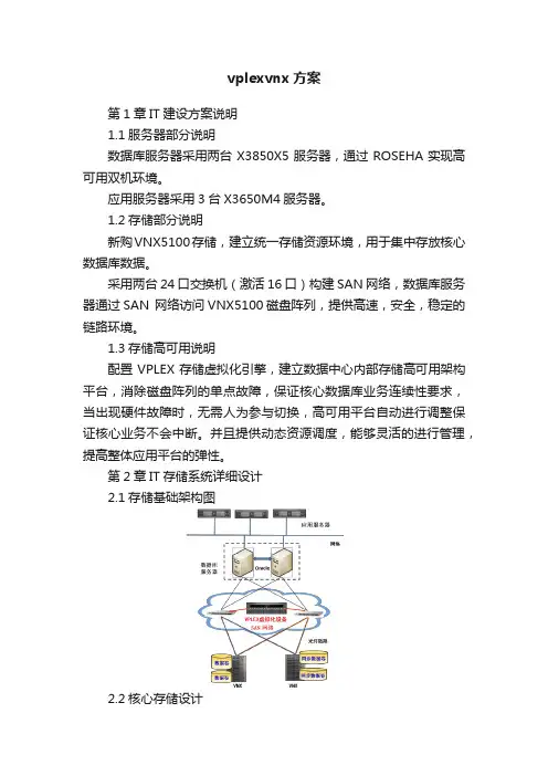
第2章IT存储系统详细设计2.1存储基础架构图2.2核心存储设计针对客户的需求,推荐使用一台EMC VNX系列统一存储产品作为数据库的核心存储。
VNX是EMC新一代的中端存储产品,它将Celerra (NS) 和 CLARiiON (CX4) 统一到单个产品品牌中,将 Celerra 和 CLARiiON 的所有价值推广到VNX 系列的客户。
它面向要求高级功能、灵活性和可配置性的中端和企业存储环境。
VNX 系列在效率、简洁性和性能上有巨大的进步。
VNX 建议配置如下:VNX5100磁盘阵列:双SAN控制器,8G高速缓存,4个8Gb FC前端口,配置4个6Gb四通道SAS磁盘接口,14块 600GB 15000转SAS硬盘。
配置图形化管理软件Unisphere。
配置说明:使用了600GB 15000转的SAS盘(核心数据库数据),同样类型硬盘做RAID5数据保护,并且配置了hot spare热备盘,提升磁盘阵列的可靠性和安全性;配置容量足以支持客户现有业务发展和数据增长;同时通过8Gb/s FC光纤链路将磁盘阵列两个控制器的FC主机端口分别与两台FC光纤交换机相连,实现磁盘阵列的链路冗余和负载均衡;通过基于WEB的阵列管理软件Unisphere可以在单一WEB管理界面实现存储管理和监控,操作简单易懂。
EMC VPLEX 连接示意图
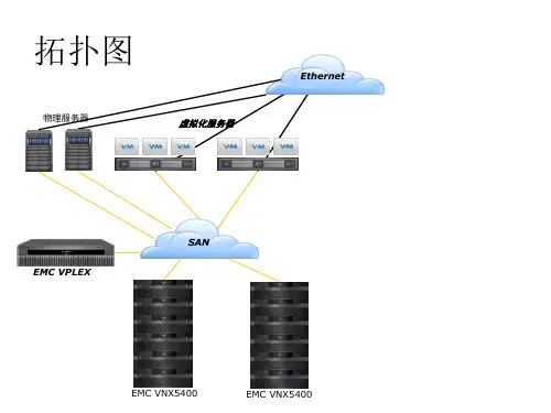
拓扑图
Ethernet 物理服务器
虚拟化服务器
SAN EMC VPLEX
EMC VNX5400
EMC VNX5400
VPLEX– 连接示意图
0.2 到 0.5 ms 的延 迟
服务器
ห้องสมุดไป่ตู้
服务器
SAN交换机
SAN交换机
VNX 5400
之前
VNX 5400
之后
关于VPLEX单点故障的疑问
• VPLEX是独立专业硬件,不影响主机和存储的性能,不影 响主机与存储的逻辑关系,可以根据需要扩展性能。 • VPLEX本身具有99.999%的高可用性,每个引擎具备双控制 器,硬件上完全冗余,同时达可以扩展多个节点。 • 即使退一万步来讲,所有的VPLEX都坏掉了,存储上的数 据还是可以访问的。只要通过相关主机命令如:AIX的 cfgmgr等重新识别设备就能访问磁盘了。 • VPLEX 能够提高主机对存储数据读写的性能。Vplex所有的 写是Write Through,同时还可以组成Cluster做横向扩展, 而且VPLEX采用分布式横向扩展的集群架构,按需添加 VPLEX引擎线性扩展性能。
EMCVPLEX数据中心虚拟化方案

02
方案设计
根据需求分析结果,设计符合客户需 求的虚拟化方案,包括资源分配、网 络设计、安全策略等。
01
03
安装部署
根据设计方案进行虚拟化软件的安装 和硬件资源的配置。
上线运行
将虚拟化系统正式投入使用,并进行 长期的监控和维护。
05
04
系统调试
对安装好的虚拟化系统进行调试,确 保系统的稳定性和性能。
实施效果
通过虚拟化方案的实施,该企业的数据中心性能得到了显著提升,同时降低了运营成本, 提高了服务质量和可靠性。容灾备份方案的实施也确保了数据的安全性和业务的连续性。
06
EMC Vplex未来展望与 总结
Vplex未来发展趋势
扩展性
Vplex继续提供更高的可扩展性,以满足不 断增长的数据需求。
安全
04
EMC Vplex解决方案详 解
Vplex数据中心架构
架构概述:Vplex数据中心架构是一种高 度可扩展的虚拟化平台,旨在提高数据 中心的效率、灵活性和可用性。
多租户支持:Vplex支持多租户隔离,为 不同业务部门提供独立的资源池。
分布式架构:Vplex采用分布式架构,可 扩展至数千个节点,满足大型企业的需 求。
02
数据中心虚拟化概述
什么是数据中心虚拟化?
数据中心虚拟化是一种将物理服务器和基础设施资源抽象成逻辑资源的技术,它 允许在一个物理服务器上运行多个虚拟机,每个虚拟机都有自己的操作系统和应 用程序。
数据中心虚拟化通过软件定义的网络和存储技术,将网络和存储资源划分为可动 态分配的虚拟机,从而提高了服务器的利用率,简化了管理流程,并降低了运营 成本。
纵向扩展:Vplex支持 纵向扩展,通过升级硬 件设备提高单节点的性 能和容量。
EMCVPLEX安装实施计划方案
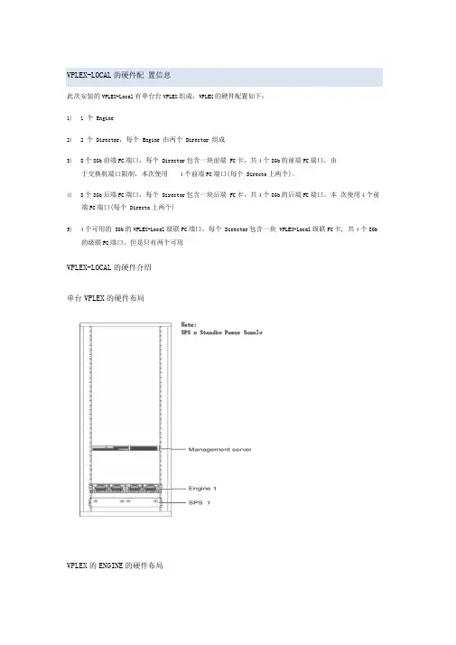
VPLEX-LOCAL 的硬件配置信息此次安装的VPLEX-Local有单台台VPLEX组成,VPLEX的硬件配置如下:1) 1 个Engine2) 2 个Director,每个Engine 由两个Director 组成3)8个8Gb前端FC端口,每个Director包含一块前端FC卡,共4个8Gb的前端FC端口,由于交换机端口限制,本次使用4个前端FC端口(每个Directo上两个)。
4)8个8Gb后端FC端口,每个Director包含一块后端FC卡,共4个8Gb的后端FC端口。
本次使用4个前端FC端口(每个Directo上两个)5)4个可用的8Gb的VPLEX-Local级联FC端口,每个Director包含一块VPLEX-Local级联FC卡, 共4个8Gb的级联FC端口,但是只有两个可用VPLEX-LOCAL的硬件介绍单台VPLEX的硬件布局VPLEX的ENGINE的硬件布局Note:SPS = Standby Power SupplyVPLEX-LOCAL 的级联端口连接Cluster 1(sama connections from each engine in clusterCluster 2^same connections from each engine in duster)int&ncluste r i 一 COM SAN —switch 1BinlorcluslorCOM SAN >switch 20 —VPLEX-LOCAL 拓 扑结构=1B2TC00 A2-FOOOB2-FC01A2-FO01int&rciuster ISL 1 inierciusierCOM SAN COM SAN switch 1A switch 2AB2 FC00 A2 FCOONOTE: ISLTisIntar-switcli linkB2-FOO1 A2-FC01IOM BO IOM 81IOM B2 / IOM B3一口口口 DO 口口口吕吕 。
EMC VPLEX-Hardware-Installation-Guide
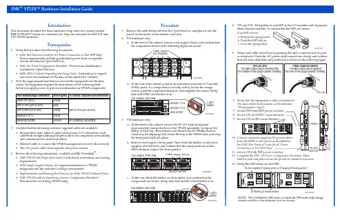
IntroductionThis document describes the basic hardware setup tasks for a factory-racked EMC® VPLEX™ cluster at a customer site. Steps are included for both VS1 and VS2 VPLEX hardware.Prerequisites1.Verify that you have the following documents:•EMC Best Practices Guide for AC Power Connections in Two-PDP Bays - Power requirements, including redundant power feeds on separate circuits (included in Open First box)•EMC AC Power Configuration Worksheet - Power zone identification (included in Open First box)•EMC 40U-C Cabinet Unpacking and Setup Guide - Instructions to unpack and secure the hardware in the data center (attached to cabinet)2.Note the approximate time that you moved the equipment into the data center. The equipment requires the time shown in the following table before you apply power, to prevent condensation on VPLEX components.3.Confirm that the following customer-supplied cables are available:•Enough fiber-optic cables to make all necessary I/O connections, each cable with enough additional length to allow for component serviceability and a minimum two-inch bend radius •Ethernet cable, to connect the VPLEX management server to the network •Two AC power cables from separate site power sources4.Review the following information, available on EMC Powerlink ®:•EMC VPLEX Site Preparation Guide , for electrical, mechanical, and cooling requirements •EMC Simple Support Matrix , for support information on VPLEX integration into the customer’s storage environment •Implementation and Planning Best Practices for EMC VPLEX Technical Notes •EMC VPLEX with GeoSynchrony (version) Configuration Worksheet - Download for use during VPLEX setupProcedure1.Remove the cable holder kit from the Open First box, and place it into the pouch on the inside of the cabinet’s rear door.2.VS1 hardware only:a.At the front of the cabinet, remove each engine’s bezel, and confirm that the components shown in the following figure are secure:b.At the rear of the cabinet, push in on each director and the I/O module (IOM) carrier. If a component is not fully seated, loosen the orange screws, push the component firmly in, and retighten the screws. Verify that each IOM’s latch button is in:3.VS2 hardware only :a.At the front of the cabinet, remove the 2U (3.5 inch) front panelapproximately nine inches below the VPLEX nameplate, to expose the laptop service tray. Then remove and discard the two Phillips screws (used only for shipping) that secure the tray to the NEMA rails, and snap the front panel back into place.b.Remove each engine’s front panel. Then check the latches on all power supplies, and directors, and confirm that the components are secure. When finished, replace the front panel(s).c.At the rear, check the latches on all modules, and confirm that the4.VS1 and VS2 - Pull gently on each SFP on the I/O modules and (if present) Fibre Channel switches, to confirm that the SFPs are secure.5.Verify each cable connection by pressing the cable connector into its port or receptacle. Check the AC power cable connections closely, and confirm that any wire cable bales are positioned as shown in the following figure.13.Verify the LED status on each SPS:NOTE: The On-Battery LED stays on while the SPS units fully charge (which could be a few minutes or a few hours).From transit/storage environment Time required To nominal computer room environment Above 75o F (24o C) 4 hours 68o F to 72o F (20o C to 22o C)68o F to 72o F (20o C to 22o C)None 40o F to 65o F (4o C to 18o C) 4 hours Below 40o F (4o C)8 hours Damp/high humidity16 hoursAir conditioned, low humidity14.Connect customer-supplied fiber-optic cables from the front-end andback-end SANs to the appropriate VPLEX I/O ports. Do not touch the ends of any fiber-optic cable, to avoid damage or contamination.Use redundant physical Fibre Channel links to connect each host to theVPLEX directors, as well as each VPLEX director to the back-end storage. To prevent data unavailability, ensure that each host in a storage view has paths to at least two directors in a cluster, and that multipathing is configured to distribute the paths evenly between directors A and B in each engine:15.Route the cables to the sides of the cabinet as shown in the followingfigure, to prevent blocking components. Maintain a minimum radius oftwo inches for any bend in a Fibre Channel cable. (In a VS2 cabinet, route the cables along the cable management trays.)Route the cables up or down the sides of the cabinet through the plastic cable holders, and out the top or bottom of the cabinet.16.Connect the management server to the customer IP network:17.VPLEX Metro™ or VPLEX Geo™ only - Connect the intercluster cables asshown in the figure that applies to your WAN COM connection. Ensurethat each director has two independendent paths to each director in theother cluster. (The connections are the same for each engine in a cluster.)•VS1 directors with WAN connections over Fibre Channel:•VS1 directors with WAN connections over IP:•VS2 directors with WAN connections over Fibre Channel:•VS2 directors with WAN connections over IP:Next steps1.Download and install the VPLEX Procedure Generator from Powerlink toaccess additional service, maintenance, and troubleshooting information.2.Work with the customer to complete the EMC VPLEX with GeoSynchrony(version) Configuration Worksheet, and give it to the customer.3.Follow the procedures in the EMC VPLEX with GeoSynchrony (version)Configuration Guide to configure the cluster for operation in the customerenvironment.Copyright © 2011 EMC Corporation. All rights reserved.Published June 2011EMC believes the information in this publication is accurate as of its publication date. However, the information issubject to change without notice.THE INFORMATION IN THIS PUBLICATION IS PROVIDED “AS IS.” EMC CORPORATION MAKES NOREPRESENTATIONS OR WARRANTIES OF ANY KIND WITH RESPECT TO THE INFORMATION IN THISPUBLICATION, AND SPECIFICALLY DISCLAIMS IMPLIED WARRANTIES OF MERCHANTABILITY ORFITNESS FOR A PARTICULAR PURPOSE.Use, copying, and distribution of any EMC software described in this publication require an applicable softwarelicense.For the most up-to-date regulatory document for your product line, go to the Technical Documentation andAdvisories section on EMC Powerlink.For the most up-to-date listing of EMC product names, see EMC Corporation Trademarks on .All other trademarks used herein are the property of their respective owners.P/N 300-012-308 Rev A01。
EMC vplex Isilon DD存储备份双活系统实施方案
2016年3月目录1.项目实施内容 (5)1.1存储系统架构示意图 (6)1.3本项目设备硬件配置 (6)2.存储系统实施基础配置 (7)2.1双活数据中心存储实现模式 (7)2.2光纤通道交换机端口连接表 (8)2.3VPLEX端口作用描述 (9)2.4VPLEX端口的使用 (9)2.5存储设备线路连接描述 (9)2.6存储设备端口命名规则 (10)3.SAN存储规划 (10)3.1存储设备连接线缆数量及种类 (10)3.2存储设备IP地址配置 (11)3.3VPLEX的端口连接配置 (11)4.VPLEX METRO实施步骤 (12)4.1VPLEX前期准备 (12)4.1.1 system volumes (12)4.2S WITCH ZONING (13)4.3B ACKEND STORAGE PROVISIONQ (13)4.4VPLEX INITIAL SETUP (13)4.4.1 Configip address and hostname of VPLEX (13)4.4.1.1 Connect to management server (13)4.4.1.2 entering the VPLEXCLI (14)4.4.1.3 set the management server ipaddress (14)4.4.1.4 change the hostname of VPLEX (14)4.4.1.5 check software version (14)4.4.2 use EZ-setup to initialize the VPLEX1 (15)4.4.2.1 Start EZ-setup (15)4.4.2.2 Configure the first cluster (15)4.4.2.3 Chose the local authentication (15)4.4.2.4 Configure event notification (15)4.4.2.5 Configure send system report to EMC (16)4.4.2.6 Configure performance statistics collector (16)4.4.2.7 Generate the certificate (16)4.4.2.8 Backend storage discovery (17)4.4.2.9 create meta-data volume (17)4.4.2.10 verify if meta-data volume is successfully created (18)4.4.2.11 create meta-data volume backups (18)4.4.2.12 enable FE port (18)4.4.3 use EZ-setup to initialize the VPLEX2 (18)4.4.3.1 Connect to VPLEX2 (18)4.4.3.2 Sychronize the time on the clusters (18)4.4.3.3 Start EZ-setup on cluster2 (19)4.4.3.4 Configure the Meta-data volume and backup of VPLEX2 (19)4.4.3.5 Complete configuration of cluster1 (19)4.4.3.6 Complete configuration of cluster2 (19)4.4.4 Join the clusters (19)4.4.5 Create logging volumes (20)4.5C HECK THE CLUSTER HEALTH (21)4.6VPLEX BACKEND STORAGE CONNECTIVITY VERIFY (21)4.7C LAIM THE DA TA VOLUME (21)5.ISILON的实施步骤 (23)5.1集群初始化 (23)5.2节点加入 (37)5.3系统健康检查 (38)5.4O NE FS升级 (38)5.5安装补丁包 (38)5.6系统微码升级 (38)5.7硬盘微码升级 (38)5.8管理界面登录 (39)5.9保护级别设置 (39)5.10网络设置 (40)5.10.1 内网设置 (41)5.10.2 外网设置 (41)5.11目录认证服务 (41)5.12SMB共享规划 (41)5.13NFS共享规划 (43)6DATADOMAIN配置步骤 (45)6.1D A TA D OMAIN配置之前实施内容 (45)6.2D A TA D OMAIN VTL配置 (46)7存储设备的使用示范 (55)7.1操作流程 (55)7.2操作示例 (56)7.2.1 光纤交换机操作部分 (56)7.2.2 EMC VNX7600操作部分 (59)7.2.3 VPLEX 操作部分 (62)1.项目实施内容XX公司双活数据中心灾备项目采用EMC VPLEX METRO解决方案,实现院区主机房和灾备机房容灾。
EMC_VPlex存储双活建设方案详细
2012年11月
一、
目前XXX市社保已经在使用EMC的存储系统VNX5100,为了进一步保障社保应用的高可用性,提高生产的安全级别,XXX市社保计划对目前的存储系统进行虚拟化整合,并搭建双活存储系统,保证关键业务所使用的存储系统即使有一台存储系统出现故障,也不会出现业务停顿,达到更高的生产安全保障。
VNX 7500还支持LUN的条带化或级联式扩展,以将数据分散到更多的磁盘上;
C.中心机房-存储虚拟化:以EMC VPlex Local作为存储虚拟化;应用系统只需要访问虚拟化存储,而不需要直接管理后端的具体的存储系统;通过存储虚拟化,可以达到两台存储之间双活,可以支持异构的存储系统,对数据进行跨存储的本地及远程保护,统一管理接口和访问接口;
当应用系统读数据时,VPlex采用了AccessAnywhere技术,应用系统只需要就近访问最近的一台存储系统即可,可以大大节省两个数据中心之间的网络传输带宽;
当存储系统故障时,VPlex采用的Active-Active技术,结合服务器的集群文件系统(Cluster File System ),可以保证应用实时切换到容灾中心,而不需要人工操作,保证了业务系统的高可用性,大大缩减了故障切换时间。
当VPlex系统自身出现故障时,由于在Vplex中的设置,VPlex不会修改存储系统LUN的配置信息,即,用户可以将存储系统A或B的LUN直接挂到应用系统,保证应用系统的继续运行,不会产生数据丢失。
2.
VPlex在提供虚拟化的存储访问的同时,还可以方便地对存储容量进行扩展。当一台存储系统出现空间不足的情况时,可以通过VPlex的虚拟卷,将多台存储系统的空间组成一个卷给应用使用。通过这种级联方式,应用系统直接访问VPlex的虚拟卷,而VPlex后端接入的存储系统只是作为VPlex虚拟卷的存储资源池使用,达到资源的更合理分配和优化。
EMCVPLEX安装实施实施方案
EMCVPLEX安装实施实施方案————————————————————————————————作者:————————————————————————————————日期:VPLEX-LOCAL的硬件配置信息此次安装的VPLEX-Local有单台台VPLEX组成,VPLEX的硬件配置如下:1)1个Engine2)2个Director,每个Engine由两个Director组成3)8个8Gb前端FC端口,每个Director包含一块前端FC卡,共4个8Gb的前端FC端口,由于交换机端口限制,本次使用4个前端FC端口(每个Directo上两个)。
4)8个8Gb后端FC端口,每个Director包含一块后端FC卡,共4个8Gb的后端FC端口。
本次使用4个前端FC端口(每个Directo上两个)5)4个可用的8Gb的VPLEX-Local级联FC端口,每个Director包含一块VPLEX-Local级联FC卡,共4个8Gb的级联FC端口,但是只有两个可用VPLEX-LOCAL的硬件介绍单台VPLEX的硬件布局VPLEX的ENGINE的硬件布局VPLEX-LOCAL的级联端口连接VPLEX-LOCAL拓扑结构VPLEX-LOCAL 的FABRIC 拓扑图Fabric Switch Engine power supplyManagement serverFabric SwitchVNX VNXVPLEX Host HostVPLEX-LOCAL 后端存储系统的配置VMAX_3358Vplex Meta volume ( >= 78GB, using 144GB )Vplex Meta volume backup ( >=78GB, using 144GB )VPLEX logging volume ( >=10GB, using 72GB )Host data volumeVMAX_0251HOST_BAKHOST_PRD VPLEX_0550VPLEX_0549Host data volumeHost data volumeMETA VOLUME的配置请注意每台VNX必须使用两个RG,每个RG各提供两个80G LUN。
vplex实施方案
vplex实施方案Vplex实施方案Vplex是一种基于存储虚拟化技术的解决方案,可以帮助企业实现存储资源的灵活管理和高可用性。
在实施Vplex方案之前,我们需要对环境进行充分的评估和规划,以确保实施过程顺利、稳定。
本文将从Vplex实施的准备工作、实施步骤和注意事项等方面进行介绍。
首先,进行准备工作。
在实施Vplex方案之前,我们需要对现有的存储环境进行详细的调研和评估,包括存储设备的型号、性能、容量、连接方式等信息。
同时,还需要对存储网络、主机配置等进行全面的了解。
在评估的基础上,我们可以制定详细的实施方案,包括资源调配、网络连接、数据迁移等计划。
其次,进行实施步骤。
在实施Vplex方案的过程中,我们需要按照事先制定的计划,依次进行资源调配、网络连接、数据迁移等操作。
首先,我们需要对Vplex设备进行初始化和配置,确保其与现有存储环境兼容。
然后,进行存储资源的调配和网络连接,确保Vplex设备能够正常工作。
最后,进行数据迁移,将现有的存储数据迁移到Vplex设备上,确保数据的完整性和一致性。
在实施Vplex方案的过程中,还需要注意一些事项。
首先,要确保实施过程中的数据迁移和操作不会对业务造成影响,可以选择在业务低峰期进行。
其次,要对Vplex设备进行充分的测试,确保其性能和稳定性。
最后,还需要对实施过程进行详细的记录和总结,为后续的运维工作提供参考。
综上所述,Vplex实施方案是一个复杂的过程,需要充分的准备和规划。
只有在充分了解现有环境的基础上,制定详细的实施计划,并严格执行,才能确保Vplex方案的顺利实施和稳定运行。
希望本文的介绍能够对您有所帮助,谢谢阅读。
Vplex实施手册
Vplex-Metro实施手册项目名称:标题文档版本号: 1.1 文档作者:生成日期:文档维护记录版本号维护日期作者/维护人描述1.01. 系统topo (6)2. 系统概述 (7)3. 系统配置前准备 (7)3.1. VNX 5700配置(代理商完成) (7)3.2. 光纤线部署 (7)3.3. 网线部署 (8)3.4. 在san switch上创建alias (8)4. vplex配置步骤 (10)4.1. 配置VPLEX的hostname和管理网口IP (10)4.1.1. 配置AVPLEX01的hostname和管理网口IP (10)4.1.2. 配置BVPLEX01的hostname和管理网口IP (10)4.2. Cluster1 EZ-SETUP (10)4.3. 分配AVNX570001磁盘给AVPLEX01 BE port (11)4.3.1. 创建AVNX570001到AVPLEX01 BE PORT的zoning (11)4.3.2. 在AVNX570001上注册AVPLEX01 (11)4.3.3. 在AVNX570001创建LUN (11)4.3.4. 在AVNX570001上创建storage group (12)4.4. 继续cluster1安装 (12)4.4.1. 继续EZ-SETUP (12)4.4.2. 配置meta-volume (12)4.4.3. 配置meta-volume backup (12)4.4.4. enable vplex FE port (12)4.5. Cluster2 和Cluster1时间同步 (12)4.6. Cluster2 EZ-SETUP (12)4.7. 分配BVNX570001磁盘给BVPLEX01 BE port (13)4.7.1. 创建BVNX570001到BVPLEX01 BE PORT的zoning (13)4.7.2. 在BVNX570001上注册BVPLEX01 (13)4.7.3. 在BVNX570001创建LUN (14)4.7.4. 在BVNX570001上创建storage group (14)4.8. 继续cluster2安装 (14)4.8.1. 继续EZ-SETUP (14)4.8.2. 配置meta-volume (14)4.8.3. 配置meta-volume backup (14)4.9. 在cluster1上完成系统配置 (15)4.10. 在cluster2上完成系统配置 (15)4.11. 配置WAN interface连接 (15)4.12. cluster2 join cluster (15)4.13. 配置cluster2 上的logging volume (15)4.14. 配置cluster1 上的logging volume (16)5. 升级vplex到最新版本 (16)5.1. 在cluster1上执行pre-check (16)5.2. 升级cluster1的management server (16)5.3. 在cluster2上执行pre-check (16)5.4. 升级cluster2的management server (16)5.5. 在cluster1上 (16)6. Vplex Witness部署 (17)6.1. 登陆到ESXi,通过OVA文件部署Witness的VM (17)6.2. Poweron Witness vm,登录到console进行配置 (17)6.3. 配置三路VPN (17)6.3.1. 配置cluster1 上配置三路VPN (17)6.3.2. 配置cluster2 上配置三路VPN (17)6.3.3. 在cluster1 上确认VPN状态 (17)6.3.4. 在cluster2 上确认VPN状态 (17)7. 创建virtual volume (17)7.1. Claim storage volume (17)7.1.1. Claim cluster1的storage volume (17)7.1.2. Claim cluster2的storage volume (18)7.2. 在cluster1上创建extent (18)7.3. 在cluster2上创建extent (21)7.4. 在cluster1上创建device (21)7.5. 在cluster2上创建device (25)7.6. 创建distributed devices (25)8. ESXi磁盘分配 (30)8.1. 安装powerpath/VE (30)8.1.1. 安装esxcli (30)8.1.2. 安装powerpath/VE (30)8.1.3. Reboot esxi 服务器 (30)8.1.4. 安装rtools (30)8.2. 创建ESXi到VPLEX FE PORT的zoning (31)8.2.1. 创建ESXi到同SAN switch相连的VPLEX的zoning (31)8.2.2. 创建ESXi到同SAN switch相连的VPLEX的zoning (32)8.3. 在BVPLEX01上注册ESXi initiator (33)8.4. 在AVPLEX01上注册ESXi initiator (34)8.5. 在BVPLEX01上创建storage view (35)8.6. 在ESXi上扫描磁盘 (38)8.7. 在ESXi上创建Datastore (40)9. 可用性测试 (40)9.1. 测试前准备 (40)9.2. 拔vplex前端口测试 (40)9.3. 拔vplex后端口测试 (41)9.4. 拔vplex wan 光纤测试 (41)9.5. 关闭后端存储测试 (41)9.6. 关闭一台vplex测试 (41)10. 系统当前配置 (41)10.1. 密码配置 (41)10.2. VNX5300配置信息 (42)10.2.1. AVNX570001配置信息 (42)10.2.2. BVNX570001配置信息 (42)10.3. VPLEX配置 (42)10.3.1. Cluster_1配置信息 (42)10.3.2. Cluster_2配置信息 (42)10.4. SAN switch配置 (43)10.4.1. Fabric1配置 (43)10.4.2. Fabric2配置 (43)1.系统topo2.系统概述本次xxx使用EMC Vplex Metro技术来实现存储系统的高可用访问,系统topo结构入第一节所示,两台VPLEX CLUSTER各自使用后端口链接一台VNX5300,其前端口供4台ESXi服务器交叉访问。
- 1、下载文档前请自行甄别文档内容的完整性,平台不提供额外的编辑、内容补充、找答案等附加服务。
- 2、"仅部分预览"的文档,不可在线预览部分如存在完整性等问题,可反馈申请退款(可完整预览的文档不适用该条件!)。
- 3、如文档侵犯您的权益,请联系客服反馈,我们会尽快为您处理(人工客服工作时间:9:00-18:30)。
VPLEX-LOCAL的硬件配置信息此次安装的VPLEX-Local有单台台VPLEX组成,VPLEX的硬件配置如下:1)1个Engine2)2个Director,每个Engine由两个Director组成3)8个8Gb前端FC端口,每个Director包含一块前端FC卡,共4个8Gb的前端FC端口,由于交换机端口限制,本次使用4个前端FC端口(每个Directo上两个)。
4)8个8Gb后端FC端口,每个Director包含一块后端FC卡,共4个8Gb的后端FC端口。
本次使用4个前端FC端口(每个Directo上两个)5)4个可用的8Gb的VPLEX-Local级联FC端口,每个Director包含一块VPLEX-Local级联FC卡,共4个8Gb的级联FC端口,但是只有两个可用VPLEX-LOCAL的硬件介绍单台VPLEX的硬件布局VPLEX的ENGINE的硬件布局VPLEX-LOCAL的级联端口连接PLEX-LOCAL 拓扑结构VPLEX-LOCAL 的FABRIC 拓扑图Fabric Switch Engine power supplyManagement serverFabric SwitchVNX VNXVPLEX Host HostVPLEX-LOCAL 后端存储系统的配置VMAX_3358Vplex Meta volume ( >= 78GB, using 144GB )Vplex Meta volume backup ( >=78GB, using 144GB )VPLEX logging volume ( >=10GB, using 72GB )Host data volume VMAX_0251HOST_BAKHOST_PRD VPLEX_0550VPLEX_0549Host data volume Host data volumeMETA VOLUME 的配置请注意每台VNX 必须使用两个RG ,每个RG 各提供两个80G LUN 。
Mirror 和backup 的meta volume LUN 需分开RG 存放。
不推荐mirror 和 backup 放在同一个RG 里。
ClusterMeta Volume Storage RAID Group LUN ID RAID Size VPLEX_01Meta_Mirror_1VNX5400RG1800RAID1080GB Meta_Bcakup_1VNX5400RG1801RAID1080GB Meta_Mirror_2VNX5400RG0800RAID1080GB Meta_Backup_2VNX5400RG0801RAID1080GB LOGGING VOLUME 的配置Cluster Log Volume Storage RAIDGroup LUN ID RAID SizeVPLEX_01Loggin_Mirror_1VNX5400802RAID1010GB Mirror 2VNX5400802RAID1010GBVPLEX-LOCAL 安装配置流程VPLEX-LOCAL安装配置详细步骤在VPLEX-Local的安装配置过程中,有些命令在Manager Server上运行,有些命令在VPLEX 上运行,以下标志代表命令的运行场所:【MS_CLUSTER_1】: VPLEX_01的Manager Server的shell环境下运行【VPLEXCLI_CLUSTER_1】: VPLEX_01的VPlex的CLI环境下运行,在Manager Server的shell 环境下,运行“vplexcli”命令进入该环境【MS_CLUSTER_2】: VPLEX_02的Manager Server的shell环境下运行【VPLEXCLI_CLUSTER_2】: VPLEX_02的VPlex的CLI环境下运行,在Manager Server的shell 环境下,运行“vplexcli”命令进入该环境CLUSTER_1的安装配置CLUSTER_1的初始化配置1.将配置用的笔记本电脑的网卡设置为通过DHCP获取IP2.配置用的笔记本电脑通过网线连接到VPLEX_01的Manager Server的eth1网口3.通过或SecureCRT软件登陆到VPLEX_01的Manager Server上,Host IP:,Connect type:SSH,用户名:service,密码:Mi@Dim7T4.设置Manager Server的主机名【MS_CLUSTER_1】# sudo /opt/emc/VPlex/tools/ipconfig/ -n VPLEX-015.重新登陆Manager Server,查看提示符或/etc/HOSTNAME文件内容,确认主机名更改成功【MS_CLUSTER_1】# cat /etc/HOSTNAME6.运行vplexcli命令登陆到VPLEX_01,用户名为service,密码为Mi@Dim7T【MS_CLUSTER_1】# vplexcli7.配置Manager Server的管理公用IP地址【VPLEXCLI_CLUSTER_1】# management-server set-ip -i VPLEX_01_IP:VPLEX_NETMASK -g VPLEX_GATEWAY eth3【VPLEXCLI_CLUSTER_1】# ll /management-server/ports/eth38.运行exit命令,退出VPLEX_01到Manager Server,检查公用管理网络的连通性【VPLEXCLI_CLUSTER_1】# exit【MS_CLUSTER_1】# ping VPLEX_GATEWAY9.配置NTP时钟服务器,同步时间【MS_CLUSTER_1】# vi /etc/ ; 设置外部server为NTP_IP【MS_CLUSTER_1】# sudo /etc/ntp restart【MS_CLUSTER_1】# date10.运行exit命令,退出VPLEX_01的Manager Server【MS_CLUSTER_1】# exit启动CLUSTER_1的DIRECTOR,检查和确认版本信息11.通过或SecureCRT软件登陆到VPLEX_01的Manager Server上,用户名为service,密码为Mi@Dim7T12.运行vplexcli命令登陆到VPLEX_01,用户名为service,密码为Mi@Dim7T【MS_CLUSTER_1】# vplexcli13.启动VPLEX的Director,确认显示的director数量正确(2个director)【VPLEXCLI_CLUSTER_1】# configuration connect-local-directors【VPLEXCLI_CLUSTER_1】# ll /engines/**/directors14.检查VPLEX及每个Director的版本,确认符合版本控制要求【VPLEXCLI_CLUSTER_1】# version【VPLEXCLI_CLUSTER_1】# exit检查硬件运行状态15.检查VPLEX及每个Director的版本,确认符合版本控制要求【MS_CLUSTER_1】VPlexPlatformHealthCheck确认检查结果符合下表:运行EZ-SETUP配置向导16.运行EZ-Setup配置向导,完成以下方面的配置:【MS_CLUSTER_1】# vplexcli【VPLEXCLI_CLUSTER_1】# configuration system-setup提示选择2 What would you like to configure?1. Configure a VPLEX Local (single cluster).2. Configure a VPLEX Metro (synchronous, 2 clusters).3. Configure a VPLEX Geo (asynchronous, 2 clusters).Select your configuration choice. (1-3)1What would you like to configure?1. Configure the first or only cluster.2. Configure the second cluster of a VPLEX Metro implementation.Select your configuration choice. (1,2)Are you sure you want to configure the first or only cluster? (yes/no):yesWould you like to configure the login banner? (yes/no):noWould you like to configure an authentication service provider to authenticate VPLEX users?no(yes/no) [no]:Would you like to configure this cluster to send event notifications to EMC? (yes/no) [yes]:noWould you like to configure this cluster to send system reports to EMC? (yes/no) [yes]:noWould you like to configure the cluster to run the SNMP Agent Service? (yes/no) [no]:no5How m any years should the CA c ertificate remain valid before expiring? EMC recommends 5 years(maximum is 5 years). [5]:2How many years should the host certificate remain valid before expiring? EMC recommends 2years (maximum is 2 years). [2]:Would you like to run the setup process now? (yes/no):yesguizhou_sfdx Please create a passphrase (at least 8 characters) for the Certificate Authority Key. Makea note of this passphrase as you will need it to configure a second cluster of a VPLEX Metroor Geo. Certificate Authority passphrase:Re-enter the passphrase for the Certificate Authority Key:guizhou_sfdxguizhou_sfdx Please create a passphrase (at least 8 characters) for the Local Host Certificate Key. Makea note of this passphrase as you will need it later. Host Certificate passphrase:Re-enter the passphrase for the Certificate Key:guizhou_sfdx 配置CLUSTER_1与后端存储系统之间的ZONE17.获取VPLEX_01端口的WWN【VPLEXCLI_CLUSTER_1】# ll /engines/**/ports18.登陆到SAN Switch,运行“switchshow”命令,检查VPLEX_01后端端口在SAN Switch上的连接是否符合规划,否则根据规划进行调整19.登陆到SAN Switch,创建与Metadata Volume和Logging Volume相关的VPLEX_01后端端口与后端存储系统前端端口之间的zoneVPLEX注册到后端存储系统及磁盘分配VPLEX_01的后端端口注册到VNXVPLEX_01的后端端口在VNX上的注册配置建议如下:Host name: VPLEX_01Host IP: VPLEX_01_IPInitiator type: CLARiiON OpenFailover Mode: 4VNX上创建STORAGE GROUPStorage Group: SG_ VPLEX_01Host: VPLEX_01_1LUN: 2个78GB的Metadata Volume(800、801)和一个10GB的Logging Volume(802),以及其他数据LUN识别后端存储系统的METADATA VOLUME和LOGGING VOLUME20.识别后端存储系统和相应的磁盘设备【VPLEXCLI_CLUSTER_1】# configuration continue-system-setup创建METADATA VOLUME21.获取适合创建Metadata Volume的磁盘设备,比较VPLEX的VPD名字与VNX LUN的VPD名字,确认VNX5400的LUN 800的VPD名字和VNX5400的LUN 800的VPD名字【VPLEXCLI_CLUSTER_1】# configuration show-meta-volume-candidates22.创建Metadata Volume【VPLEXCLI_CLUSTER_1】# meta-volume create -n VPLEX_01_META -d < VXN5700的LUN 800的VPD名字>,< VNX5400的LUN 800的VPD名字>23.查看Metadata Volume的状态,确认active属性列显示为true【VPLEXCLI_CLUSTER_1】# ll /clusters/cluster-1/system-volumes/ VPLEX_01_META24.查看cluster的状态,确认cluster status和operational-status显示为ok【VPLEXCLI_CLUSTER_1】# cluster status设置METADATA VOLUME的备份时间25.获取适合创建Metadata Volume Backup的磁盘设备,比较VPLEX的VPD名字与VNX LUN的VPD名字,确认VNX5400的LUN 801的VPD名字和VNX5400的LUN 801的VPD名字【VPLEXCLI_CLUSTER_1】# ll /clusters/cluster-1/storage-elements/storage-volumes26.选择Metadata Volume的备份设备为:VNX5400的LUN 801的VPD名字>,< VNX5400的LUN801的VPD名字>。