FSK638D使用说明书
(完整版)道闸产品说明书

请您在使用产品前仔细阅读本手册尊敬的用户:首先感谢您选择了由本公司为您精心制造的道闸!能为您提供服务深感荣幸!为确保本产品的安全使用,充分发挥本产品的优良性能,提高产品的使用寿命,请通读本手册,了解相关的产品信息。
通过阅读本手册,你能更详细的了解到本产品的性能特点及相关技术参数,并通过相关示意图明确产品结构。
本手册讲述了安装过程中可能遇到的问题,并作了相关分析,提供了相应的解决方案,方便用户对产品安装调试及进行保养维护。
本资料中部分图片是示意图,仅供参考,若图片与实物不符,请以以实物为准。
本公司全权负责该资料的修订及解释,并保留更改产品及技术参数不另行通知的权利,敬请谅解。
产品性能特点我公司精心设计并制作的一款新型道闸,使用方便,安全可靠,简洁大方、美观亮丽。
广泛用于机关单位、小区、停车场、厂区大门等出入通道口。
一.机芯特性●采用最稳定的非等速运行机构,使闸杆慢起动、快运行,慢停止,排除闸杆在运行开、关中带来的抖动。
延长产品使用寿命。
●道闸左右可换向,根据现场需要可随意更换闸杆的起落方向,适用范围更加广泛。
●采用高负苛承重带座轴承,使机芯部分更加稳固。
●机械限位可调,使安装调试更加方便快捷。
●采用高灵敏限位开关,瞬间控制起杆、落杆到位准确。
●一体化涡轮蜗杆传动减速异步电机,传动平稳,噪音低,结构紧凑,能实现自锁。
●电机设智能过热保护系统,在频繁的使用下,控制了电机的温升,使电机不易烧坏。
●手动开闸机构,停电时可通过电机手轮自动起落闸杆,不受限制。
二.控制系统●采用数字芯片技术,防砸、地感、IC接口集为一体,稳定性好,误动概率为零,特别设有延时保护功能,具有双重控制功效。
●采用升降超时与电机过热保护,防止闸机非正常损坏。
●采用原装进口的大功率继电器,确保道闸可靠运行。
●采用原装进口的光电隔离保护电路,确保信号完整和抗强干扰。
●集成高性能百万组学习码的无线遥控接收模块,确保操作的稳定性。
●采用独有的灭弧处理电路,确保控制板的使用寿命。
调速器硬件手册

ETD 790直流调速器
页码:2 /86
ETD 790直流调速器 电流预测控制
6.4e 模拟输出 .............................................................................................................. 39 6.4f 422/485串行口....................................................................................................... 41 6.4g 直流测速电机反馈接线 ......................................................................................... 42 6.4h 用于指示输入和输出的LED指示器 ....................................................................... 43 6.5 RS 232、CAN总线、编码器1、编码器2的连接器....................................................
LED638T测试机.使用说明20

LED-638TLED TESTER 使用說明維明企業股份有限公司台中縣大雅鄉上楓村民豐街117號TEL: 886-4-25676189FAX: 886-4-256761882005年9月二十版LED-638T可測試發光二極體(LED)之電氣特性: VF(順向電壓), VZ(BVR逆向耐壓), IR(漏電流), DVF(IF加熱前後的VF差值), VFD(VF的暫態峰值) 以及光學特性: LOP(亮度), λp(峰波長), xyz(顏色圖座標), λd(主波長), Purity(顏色純度), HW(波寬), λc(中心波長), CCT(色溫) 等項目.LED-638T可適用於單晶或雙晶或全彩三晶等不同結構的LED封裝, 它可先對個別的LED逐一測試, 然後再進行混光測試. 測試後可將測試結果分為30類, 外加不良品及接觸不良1類. 並且另可細分65535等級. 測試條件及分類條件可由鍵盤輸入. 測試結果以液晶顯示器(LCD)顯示. 顯示項目分為五頁. 第一頁為測試條件設定及測試值顯示, 第二頁為分類條件設定, 第三頁為各分類計數器及等級條件, 第四頁為亮度與光譜校正值設定, 第五頁為光譜圖形.LED-638T具備RS232通信功能, 並有於PC視窗作業系統下執行的應用程式支援, 提供規格管理, 數據存檔, 報表印製, 自動白平衡測試等等操作, 並提供由PC處理的255等級的分類能力. 有關該應用程式的操作說明, 請另行參閱相關手冊.開機後或按[第一頁]鍵, 顯示器顯示測試條件及測試值, 共分4頁, 第一次顯示第1~1頁, 每再按[第一頁]鍵, 可於第1~1/1~2/1~3/1~4等4頁間作順序切換.1~1頁畫面如下:(1)ID: 光譜感知器的編號. 每一個光譜感知器都有個別的光譜校正係數, 因此每一台測試機均頇安裝特定編號的程式(ROM)(2)~(18)項為R-LED的電性測試條件:(2)IFH: 測試前, 使用此順向電流預先加熱待測LED0.000~4.000mA, 4.01~40.00mA, 40.1~400.0mA(3)為IFH之脈衝寬度, 0.0~99.9mS(4)IF1: 測試VF1所供應之順向電流源0.000~4.000mA, 4.01~40.00mA, 40.1~400.0mA(5)為IF1之脈衝寬度, 0.0~99.9mS經過指定的脈衝寬度後才讀取VF1值. 如果設定此時間>=16.7mS(60HZ)或>=20mS(50HZ), 則讀取VF1將自動採用電源濾波方式(可得到較穩定的讀值), 總脈衝寬度則維持不變(6)IF2: 測試VF2所供應之順向電流源. 請參閱(4)(7)為IF2之脈衝寬度. 請參閱(5)(8)IF3: 測試VF3所供應之順向電流源. 請參閱(4)(9)為IF3之脈衝寬度. 請參閱(5)(10)IFM: 測試DVF時,讀取VF所供應之順向電流源. 請參閱(4)(11)為IFM之脈衝寬度. 請參閱(5)(12)IFP: 測試DVF時,加熱使用的順向電流源. 請參閱(4)(13)為IFP之脈衝寬度. 請參閱(5)(14)IFD: 指定測試VFD暫態峰值時的掃描電流範圍0=OFF, 1=0→100uA(大約值), 2=0→25mA(大約值), 3=AUTO(自動判別) (15)IZ: 為測量VZ(BVR)所頇之逆向電流源0.00~40.00uA, 40.1~400.0uA, 401~1000uA(16)為IZ之脈衝寬度, 0.0~200.0mS經過指定的脈衝寬度後才讀取VZ值, 讀取VZ所頇時間由省時策略決定(出廠預設為一電源週期). 對於高阻抗待測物, 此項設定值請設定25mS以上(17)VR: 為測量IR所頇之逆向電壓源, 0.0~200.0V(18)為VR之脈衝寬度, 0.0~200.0mS經過指定的脈衝寬度後才讀取IR值, 讀取IR所頇時間由省時策略決定(出廠預設為一電源週期). 此項設定值請設定25mS以上(19)~(35)項為G-LED的電性測試條件, 請參閱(2)~(18)項(36)~(52)項為B-LED的電性測試條件, 請參閱(2)~(18)項1~2頁畫面如下:(1)ID: 光譜感知器的編號.(2)~(9) 項為R-LED的光學測試條件(2)IFL1: 測試LOP1(亮度1)所供應之順向電流源0.000~4.000mA, 4.01~40.00mA, 40.1~400.0mA(3)為IFL1之脈衝寬度, 0.0~99.9mS經過指定的脈衝寬度後才讀取亮度值, 讀取亮度所頇時間由省時策略決定(出廠預設為一電源週期).(4)IFL2: 測試LOP2(亮度2)所供應之順向電流源. 請參閱(2)(5)為IFL2之脈衝寬度. 請參閱(3)(6)IFWL: 測試波長時所供應之順向電流源. 請參閱(2)(7)指定測試波長的時間, 0, 10~9999mS. 請參閱(36)感光模式設定(8)VFL3: 測試LOP3(亮度3)所供應之順向電壓源.0.000~4.000V, 4.01~20.00V註: 定電壓測量LOP3為保留功能, 未來必頇加裝 [電流轉換電壓線路板] 才可執行, 目前保留. 在未加裝電壓轉換板以前, 設定值將以電流源的型式輸出, 亦即0.000~20.00V實際將輸出0.000~20.00mA(9)為VFL3之脈衝寬度. 請參閱(3)(10)~(17) 項為G-LED的光學測試條件, 請參閱(2)~(9)項(18)~(25) 項為B-LED的光學測試條件, 請參閱(2)~(9)項(26)~(30) 項為第一次混光測試的條件設定(26)R-LED 的順向電流源0.000~2.000mA, 2.01~20.00mA, 20.1~200.0mA(27)G-LED 的順向電流源, 請參閱(26)(28)B-LED 的順向電流源, 請參閱(26)(29)測量亮度的脈衝寬度, 0.0~99.9mS. 請參閱(3)(30)測量波長的脈衝寬度, 0, 10~9999mS. 請參閱(7)(31)~(35) 項為第二次混光測試的條件設定, 請參閱(26)~(30)項(36)MODE: 指定測量波長的感應時間模式, 測試波長所頇的時間依光源強度而定, 光源愈強所頇時間愈短, 反之愈長, 其測試時間介於 10~9999mS之間0=限時式: 依光源強度自動調整感應時間10mS~設定值, 最長不超過設定時間1=固定時間: 固定感應時間等於所設定的時間2=自動感應: 由光源強度自動調整感應時間10~9999mS之間其中 a/b/c/d/e分別為量測R-LED/G-LED/B-LED/混光1/混光2的感光模式(37)SORT: 指定波長的分類依據: 0=峰波長WLP, 1=主波長WLD, 2=中心波長WLC,3=主波長WLD但不要計算色溫(測試單色LED時可節省時間).當使用者指定依主波長分類時, 主波長及純度及顏色圖的(x,y,z)座標及色溫才會被計算(每計算一次WLD頇耗時約25mS, 每計算一次色溫頇耗時約40~45mS) 其中 f/g/h/i/j分別為R-LED/G-LED/B-LED/混光1/混光2的波長分類依據1~3頁畫面如下:(1)BIN: 分類結果. BIN 1~30, 31=不良品或接觸不良, (長腳錯誤為BIN30), (VF遞增或遞減錯誤為BIN29)(2)ID: 光譜感知器的編號.(3)RANK: 等級, 0~65535, 0=任一用來分等級的測試值沒有讀值如果執行由PC分類功能, 則此欄將由PC分類後傳回的等級類別碼所取代(4)TIME: 測試總時間 (根據各測試條件的時間設定加上內部開關所頇時間而定),0~9999 mS(5)TPOLAR: 測試後顯示待測物之極性結構, 1~12(6)~(15)項為R-LED的電性測試結果(6)VF1讀值, 0.000~8.000V(7)VF2讀值. 請參閱(6)(8)VF3讀值. 請參閱(6)(9)VFM1: 測試DVF時,加熱前先量測的VF讀值. 請參閱(6)(10)VFM2: 測試DVF時,加熱後再量測的VF讀值. 請參閱(6)(11)DVF: 加熱前後的VF差值(取絕對值) DVF = ∣VFM2-VFM1∣(12)VF: 測試VFD暫態峰值時, 在大約100uA或25mA順向電流源下(由IFD指定)的VF穩定值, 0.000~8.000V(13)VFD: 測試VFD暫態峰值時, VF峰值減去VF穩定值的差值, 0.000~8.000V(14)VZ讀值, 0.0~200.0V(15)IR讀值, 0.000~4.000uA, 4.01~40.00uA, 40.1~400.0uA測試IR時並不自動換檔, 檔位與分類條件IRH最大值的檔位相同(16)~(25)項為G-LED的電性測試結果, 請參閱(6)~(15)項(26)~(35)項為B-LED的電性測試結果, 請參閱(6)~(15)項(36)為1P,1S測試探針之接觸電阻, 0.00~40.00 毆姆(37)為2P,2S測試探針之接觸電阻, 0.00~40.00 毆姆(38)為3P,3S測試探針之接觸電阻, 0.00~40.00 毆姆(39)為4P,4S測試探針之接觸電阻, 0.00~40.00 毆姆(40)為1L,1S長腳測試之接觸電阻, 0.00~40.00 毆姆(41)為2L,2S長腳測試之接觸電阻, 0.00~40.00 毆姆(42)為3L,3S長腳測試之接觸電阻, 0.00~40.00 毆姆(43)為4L,4S長腳測試之接觸電阻, 0.00~40.00 毆姆1~4頁畫面如下:(1)~(2) 同第1~3頁(3)~(16)項為R-LED的光學特性測試結果(3)LOP1: 亮度1測試值, 0.000~65535 (亮度校正值於第四頁設定)(4)LOP2: 亮度2測試值. 請參閱(3)(5)LOP3: 亮度3測試值. 請參閱(3)(6)WLP: 光譜的峰波長, 約 300.0~1150.0nm(7)WLC: 光譜的中心波長, 約 370.0~720.0nm(8)WLD: (可見)光譜的主波長, 約 360.0~700.0nm(9)HW: 光譜波寬(Spectral Line Half Width), 0.0~999.9nm(10)PURITY: 顏色純度, 0.000~1.000(11)x: 顏色圖(x,y,z)座標中的x座標, 0.0000~1.0000, x+y+z=1(12)y: 顏色圖(x,y,z)座標中的y座標, 0.0000~1.0000(13)z: 顏色圖(x,y,z)座標中的z座標, 0.0000~1.0000, z=1-x-y(14)ST: 實際感光時間, 10~9999mS(15)INT: 相對強度(=光譜面積對感光時間的比值), 僅供參考不列入分類條件(16)CCT: 相關色溫(Correlated Color Temperature) 1000~25000 o K(17)~(30)項為G-LED的光學特性測試結果, 請參閱(3)~(16)項(31)~(44)項為B-LED的光學特性測試結果, 請參閱(3)~(16)項(45)~(56)項為第一次混光的光學特性測試結果, 請參閱(3)~(16)項(57)~(68)項為第二次混光的光學特性測試結果, 請參閱(3)~(16)項註:*** 第一次按[編輯]鍵時, 游標將出現在第一個可供設定的欄位後續每再按[編輯]鍵, 可將游標往後移到下一個設定群組如果游標所在的設定欄位可以接受負數, 則按[編輯]鍵將出現負號(-), 再按一次即取消負號如果鍵盤被鎖住, 則游標將不會出現*** 第一次按[清除]鍵時, 游標將出現在最後一個可供設定的欄位.設定新值後若按[清除]鍵, 可取消鍵入的數字,恢復原來設定值*** 按[輸入]鍵, 可更新設定值, 並將游標移到下一個可供設定的欄位如果設定值超出範圍, 按[輸入]鍵將被拒絕, 並恢復原來值*** 按[←]鍵, 可更新設定值, 並將游標移到上一個可供設定的欄位如果設定值超出範圍, 按[←]鍵將被拒絕, 並恢復原來值*** 設定測試條件時, 如果設定值為0或脈衝寬度為0, 將視為該項目不測試, 其讀值將顯示空白, 亦不納入作分類比較(視為合格)*** 測試光譜特性WLP,HW,WLC,WLD,PURITY,X,Y,Z,CCT等項目時, 如果因光度太弱或太強以致於無法計算時, 該項目將顯示‟----…, 分類比較時視為不合格§1.2按[第二頁]鍵, 顯示器將顯示分類條件, 共30BIN, 每一BIN再細分為3頁(2~1, 2~2, 2~3), 第一次顯示BIN1第2~1頁, 再按[第二頁]鍵, 依序顯示BIN1第2~2頁, BIN1第2~3頁, 再按[第二頁]鍵則顯示BIN2第2~1頁, 依此類推至BIN30. 在換頁過程中也可直接輸入BIN數值作直接切換.2~1頁畫面如下:(1)BIN: 直接切換到指定的BIN的分類條件設定頁(2)CONTH: 測試片接觸電阻上限, 0.00~40.00歐姆.BIN1~BIN30設定值中的最大值將用來作為接觸不良的判斷點, 如果任何一個接觸電阻值大於此最大值則視為接觸不良, 其餘測試項目皆不測試並且分類為31,如果所有各BIN的CONTH設定值皆為0, 則代表不測試接觸電阻(3)POLAR: 指定極性結構必頇吻合, 1~12(4)~(16)項為R-LED的電性分類條件(4)VF1L: VF1之下限, 0.000~8.000V(5)VF1H: VF1之上限, 0.000~8.000V(6)VF2L: VF2之下限, 0.000~8.000V(7)VF2H: VF2之上限, 0.000~8.000V(8)VF3L: VF3之下限, 0.000~8.000V(9)VF3H: VF3之上限, 0.000~8.000V(10)VFM1L: VFM1之下限, 0.000~8.000V(11)VFM1H: VFM1之上限, 0.000~8.000V(12)DVFH: DVF之上限, 0.000~8.000V(13)VFH: VF之上限, 0.000~8.000V(14)VFDH: VFD之上限, 0.000~8.000V(15)VZL: VZ之下限, 0.0~200.0V(16)IRH: IR之上限, 0.000~400.0uA測試機會找尋各BIN的IRH的最大值, 以其檔位作為固定的測試檔位, 測試時不作自動換檔, 並且將調整各BIN的IRH為同一解析度(17)~(29)項為G-LED的電性分類條件, 請參閱(4)~(16)項(30)~(42)項為B-LED的電性分類條件, 請參閱(4)~(16)項2~2頁畫面如下:(1)BIN: 直接切換到指定的BIN的分類條件設定頁(2)~(13)項為R-LED的光學特性分類條件(2)LOP1L: 亮度1下限, 0.000~65535(3)LOP1H: 亮度1上限, 0.000~65535測試機會以各BIN的LOP1L/LOP1H的最大值的檔位, 將各BIN調整為同一解析度(4)LOP2L: 亮度2下限, 請參閱(2,3)(5)LOP2H: 亮度2上限, 請參閱(2,3)(6)LOP3L: 亮度3下限, 請參閱(2,3)(7)LOP3H: 亮度3上限. 請參閱(2,3)(8)WLL: 波長之下限(依指定的WLP或WLD或WLC), 0, 300.0~1150.0nm(9)WLH: 波長之上限(依指定的WLP或WLD或WLC), 0, 300.0~1150.0nm(10)PURL: 顏色純度(PURITY)之下限, 0.000~1.000(11)PURH: 顏色純度(PURITY)之上限, 0.000~1.000(12)HWL: 波寬(HW)之下限, 0.0~999.9nm(13)HWH: 波寬(HW)之上限, 0.0~999.9nm(14)~(25)項為G-LED的光學特性分類條件, 請參閱(2)~(13)項(26)~(37)項為B-LED的光學特性分類條件, 請參閱(2)~(13)項(38)~(45)項為第一次混光的光學特性分類條件, 請參閱(2)~(13)項(46)~(53)項為第二次混光的光學特性分類條件, 請參閱(2)~(13)項2~3頁畫面如下:(1)BIN: 直接切換到指定的BIN的分類條件設定頁(2)~(9) 項為R-LED在顏色圖上的4點(x,y)座標分類, 0.0000~1.0000(x1,y1) (x2,y2) (x3,y3) (x4,y4) 等4點座標可在顏色圖上構成一四邊形,所量測之(x,y)點必頇落在此四邊形內或其邊線上方滿足該BIN條件(10) CCTL: R-LED色溫之下限, 0, 1000~25000 o K(11) CCTH: R-LED色溫之上限, 0, 1000~25000 o K(12)~(21) 項為G-LED在顏色圖上的4點(x,y)座標分類及色溫上下限,請參閱(2)~(11)項(22)~(31) 項為B-LED在顏色圖上的4點(x,y)座標分類及色溫上下限,請參閱(2)~(11)項(32)~(41) 項為第一次混光在顏色圖上的4點(x,y)座標分類及色溫上下限,請參閱(2)~(11)項(42)~(51) 項為第二次混光在顏色圖上的4點(x,y)座標分類及色溫上下限,請參閱(2)~(11)項註:*** 分類優先順序: 接觸不良(31) →長腳錯誤(30) → VF遞增或遞減錯誤(29) →BIN1~BIN30 →不良品(31)*** 任何欄位設定值為0, 代表該欄位不用比較 (視為合格)§1.3按[第三頁]鍵, 顯示器將顯示計數器於第3~1頁, 再按[第三頁]鍵, 則依序顯示第3~2頁, 第3~3頁的等級條件設定頁.第一次按[第三頁]鍵, 可顯示第3~1頁畫面如下:(1)TYPE: 選用測試規格 0~9選用測試規格: 於任何一頁按 [讀取], [編輯], [0~9], [輸入]複製測試規格: 將目前選用的測試規格複製到指定的Type中於任何一頁按 [儲存], [編輯], [0~9], [輸入](2)PHOTO START: 指定機械觸發測試信號(SOT)的極性0:High→Low觸發測試, 1:Low→High觸發測試(3)REJECT BINS: 測試結果的BIN值大於此設定值, 將由機械界面Driver7輸出不良品信號. 這是本測試機輸出分類別(Bin Code)的另一種測試結果輸出, 適用於Pass/Reject(Go/NoGo)的機械, 例如點測機(Prober)(4)REJECT LEVEL: 指定輸出不良品信號為低電位(0)或高電位(1)(5)MTIME: 上一次測試到本次測試所經過的時間 0~9999mS(6)PCS/SEC: 由 MTIME 可計算出每秒可測試幾個材料(7)K/HOUR: 由 PCS/SEC 可計算出每小時可測試幾K(千個)材料(8)~(37) BIN1~BIN30 的計數器符合Bin30條件或者長腳錯誤皆歸類於Bin30, 故當啟用長腳測試功能時, Bin30應保留給長腳錯誤使用符合Bin29條件或者 VF遞增或遞減錯誤皆歸類於Bin29, 故當啟用6步階IFS測試功能時, Bin29應保留給VF遞增或遞減錯誤使用(38)NG: NOGO不良品計數器(不符合Bin1~30條件的材料)(39)C1: CONT1接觸不良計數器(40)C2: CONT2接觸不良計數器(41)C3: CONT3接觸不良計數器(42)C4: CONT4接觸不良計數器如果 CONT1~CONT4的接觸電阻均大於38歐姆, 將被視為沒有材料在測試片上, 計數器將不計數(分類仍為CONT NoGo). 如果為接觸不良, 最大接觸電阻端的計數器將會計數(43)GT: 測試材料總數, 計數範圍0~999999(44)RT: 測試機開機秒數累計, 開機後每秒加一, 計時範圍0~999999 秒(45)MT: 機器運轉秒數累計, 為MTIME的時間累計, 當機械停止測試時MTIME計時上限為9999mS, 超過此時間視為機械停止運轉, 計時範圍0~999999 秒(46)RESET: 將計數器歸零: 於任何一頁按 [計數器歸零], [編輯], [0~38], [輸入]其中號碼 = 0 將所有計數器歸零 (GT,RT,MT頇各自獨立歸零)1~30 將BIN1~BIN30其中一個計數器歸零31 將NOGO計數器歸零32~35 將CONT1~CONT4其中一個計數器歸零36 將GT計數器歸零37 將RT計時器歸零38 將MT計時器歸零再次按[第三頁]鍵, 可顯示第3~2頁畫面如下:RANK-SORTING TABLE (1)--#1-----#2/3----READING CODE-----------1:R-LED 01:VF1 11:LOP1 21:z 31:CNL22:G-LED 02:VF2 12:LOP2 22:ST 32:CNL33:B-LED 03:VF3 13:LOP3 23:INT 33:CNL44:MIX-1 04:VFM1 14:WLP 24:BIN 34:TIME5:MIX-2 05:VFM2 15:HW 25:POLR 35:MTIM6:DEVICE 06:DVF 16:WLC 26:CNT1 36:PC/S07:VF 17:WLD 27:CNT2 37:K/HR08:VFD 18:PUR 28:CNT3 38:CCT09:VZ 19:x 29:CNT410:IR 20:y 30:CNL1----------------------------------------ex: 101=R--VF1, 203=G--VF3, 319=B--x411=X1-LOP1, 517=X2-WLD, 624=---BIN等級的分類是採用矩陣方式, 先選用要分級的測試項目, 再設定其組距. 例如以單一個LED為例, 我們可以將順向電壓分為4類, 亮度分為5類, 波長分為3類, 則三維矩陣相乘的結果共產生4*5*3共60等級, 我們賦予其值1~60, 但其中如有任一測試讀值沒有測試或無法計算, 則等級將無法進行分類, 其RANK值判為0, 或者是其中任何一個測試讀值超出所設定的組距範圍之外, 則其等級為不良品(NOGO)其RANK 值為最大有效等級值加1, 如上例為61. LED638T因可測試三晶及混光, 它所產生的測試項目相當的多, 在這其中LED638T可以讓我們選用最多10測試項目來進行等級分類, 每一測試項目最多可設31個數據界限(分為30等級), 但總RANK數值範圍為0~65535, 超過65535將以65535表示, 例如:VF 分4級: 界限數據為: 1.000, 2.000, 3.000, 4.000, 5.000A 組距範圍 1.000 ~ < 2.000B 組距範圍 2.000 ~ < 3.000C 組距範圍 3.000 ~ < 4.000D 組距範圍 4.000 ~ < 5.000不良品< 1.000 或>= 5.000LOP 分5級: 界限數據為: 300, 500, 700, 900, 1100, 13001 組距範圍300 ~ < 5002 組距範圍500 ~ < 7003 組距範圍700 ~ < 9004 組距範圍900 ~ < 11005 組距範圍1100 ~ < 1300不良品< 300 或>= 1300WLD 分3級: 界限數據為: 646.0, 648.0, 650.0, 652.0X 組距範圍646.0 ~ < 648.0Y 組距範圍648.0 ~ < 650.0Z 組距範圍650.0 ~ < 652.0不良品< 646.0 或>= 652.0註: 1. 如果VF/LOP/WLD等任一測試值沒有測試或無法計算, 其RANK=02. 不良品(NOGO)其RANK=61在第3~2頁中, 我們將測試項目編號, 以方便輸入, 每一項目以3碼來代表, 第1碼為數據類別, 第2,3碼為數據項目, 例如:其它測試項目依此類推再次按[第三頁]鍵, 可顯示第3~3頁畫面如下:(1) ROW: 測試項目序號, 星號代表正在設定其組距界限(2) CODE: 等級分類的測試項目代號, 0=無, 101~123/138=R-LED測試值,201~223/238=G-LED測試值, 301~323/338=B-LED測試值,411/414~423/438=混光1測試值, 511/514~523/538=混光2測試值,624~637=整個材料測試結果(3) READING: 等級分類的測試項目名稱(4) COLS: 該測試項目共分為多少組距數(等級)(5) COLUMN: 該測試項目的組距界限, 最多可設定31數據亦即分為30組距, 第一個數據與第二個數據間代表第一個組距(參與分等級的測試讀值至少一個組距), 第三個數據以後每一數據增加一個組距, 如數據值=0代表組距設定結束. 組距界限值必頇由小到大排列(6) 按<編輯>鍵, 可移動游標來回於測試項目區與組距界限區之間PC分類:PC應用程式另外提供255等級的分類功能, 可依各測試值上下限進行分類(類似BIN), 而不採用組距矩陣方式. 如果執行由PC分類功能, 則上述測試機依組距矩陣等級分類的結果, 將被PC依各測試值上下限分類後傳回來的等級碼所取代.§1.4第一次按[第四頁]鍵, 可顯示第4~1頁畫面如下:(1)~(13) 項為R-LED的光學特性校正值(1)LOP1 GAIN: 亮度1校正值, 乘以倍率, 0.001~32767(2)LOP1 OFFSET: 亮度1校正值, 加上誤差修正, ±0.000~32767當GAIN=1, OFFSET=0時, LOP1顯示值即等於亮度感應前置放大器輸出的電壓值(3)LOP2 GAIN: 亮度2校正值, 乘以倍率. 請參閱(1)(4)LOP2 OFFSET: 亮度2校正值, 加上誤差修正. 請參閱(2)(5)LOP3 GAIN: 亮度3校正值, 乘以倍率. 請參閱(1)(6)LOP3 OFFSET: 亮度3校正值, 加上誤差修正. 請參閱(2)以上設定值(1)~(6)為TYPE變數的一部份, 將隨TYPE的選用而變動(7)WLP OFFSET: WLP修正值, 加上誤差修正, ±0.0~9.9nm(8)WLC OFFSET: WLC修正值, 加上誤差修正. ±0.0~9.9nm(9)WLD OFFSET: WLD修正值, 加上誤差修正. ±0.0~9.9nm(10)X GAIN: X 修正值, 乘以倍率. 0.500~2.000(11)X OFFSET: X 修正值, 加上誤差修正. ±0.1000(12)Y GAIN: Y 修正值, 乘以倍率. 0.500~2.000(13)Y OFFSET: Y 修正值, 加上誤差修正. ±0.1000以上設定值(7)~(13)為硬體修正值, 不隨TYPE的選用而變動註1: 設定誤差修正值時, 按 [編輯] 鍵可輸入負號註2: 基本上 x y 值為Spectrum波形與λd / Purity / CCT的中間值, 這些測量結果都有相關性, 直接修改x,y值, 將造成上述的各測量結果沒有一致性, 這不是很恰當的 (因為修正x,y值, 並不因此而改變原來的Spectrum波形與λd / Purity / CCT等測試值). 我們建議, 如果發現x,y 值有誤差, 應該從…補償失真的光譜波形‟或…改善光源取樣的標準化‟來處理比較理想.(14)~(26)項為G-LED的光學特性校正值, 請參閱(1)~(13)項(27)~(39)項為B-LED的光學特性校正值, 請參閱(1)~(13)項(40)~(48)項為第一次混光的光學特性校正值, 請參閱(1)~(13)項(49)~(57)項為第二次混光的光學特性校正值, 請參閱(1)~(13)項(58)VF OFFSET: 所有VF讀值的修正值(測量VFD時的VF值除外),加上誤差修正, -0.200 ~ 0.200 V(59)VZ OFFSET: 所有VZ讀值的修正值, 加上誤差修正, -5.0 ~ 5.0 V(60)IR OFFSET: 所有IR讀值的修正值, 加上誤差修正, -100 ~ 100 E*指定數值不管檔位, 例如設定值10在各不同檔位檔位各為:0.010uA / 0.10uA / 1.0uA / 10uA(61)光譜補償: 由於光譜感知器(Grating)對於不同波長的感應度並非全部一致, 因而會造成讀取光譜失真. 廣義而言, 只要是導光介質對光譜來講皆可視為一濾波器, 比如說光纖或治具(內含透鏡組), 光線經過這些介質都會造成某種程度的失真. 當讀取的光譜失真了, 據以計算的各項光學測試值也會有所誤差.此欄設定的目的即在補償導光介質所產生的失真, 以確保讀到的光譜即為待測物實際的光譜:Bit2 Bit1 Bit0 設定值補償項目0 0 0 0 無0 0 1 1 光譜感知器0 1 0 2 UV光纖0 1 1 3 UV光纖 + 光譜感知器1 0 0 4 治具1 0 1 5 治具 + 光譜感知器1 1 0 6 治具 + UV光纖1 1 1 7 治具 + UV光纖 + 光譜感知器光譜感知器補償係數儲存在ROM中 (每個光譜感知器均經過個別校正)光纖以隨測試機所附的UV-FIBER內建補償係數於ROM中註: 如果使用其他光纖則不適用此內建補償表, 例如使用NIR光纖即不頇補償(請參閱2.9光纖的判別)治具儲存於EEPROM, 操作者可自行校正讀取的光譜圖形有關光譜圖形的校正, 請參閱2.7(62)依據波長修正測試值: 0=不修正, 1=依據峰波長修正, 2=依據主波長修正, 3=依據中心波長修正.(63)光譜視窗下限: 指定僅讀取某一範圍內的波長, 下限值300~1140nm, 0=不指定(等同於300nm), 上下限間至少要有10nm的範圍(64)光譜視窗上限: 指定僅讀取某一範圍內的波長, 上限值310~1150nm, 0=不指定(等同於1150nm), 上下限間至少要有10nm的範圍以上設定值(58)~(64)為硬體修正值, 不隨TYPE的選用而變動依據波長讀值來修正其它測試值的相關說明如下:1.目的: 隨波長修正底下3項測試值, 以克服光學組件或亮度感知器對波長響應度的誤差:(1)亮度相對倍率(Gain of LOP1 / LOP2/ LOP3)(2)峰波長偏差值(Offset of λp)(3)主波長偏差值(Offset of λd)2.作法: (1) 在波長範圍300.0 ~ 1150.0nm之間, 每隔1nm設定:a. 相對亮度修正倍率* 0.000 ~ 32.767b. 峰波長修正偏差值+ -12.8 ~ 12.7 nmc. 主波長修正偏差值+ -12.8 ~ 12.7 nm(2)可依據峰波長或主波長或中心波長來進行修正, 也可取消修正功能(3)當波長不為整數時, 以相鄰2整數波長的修正值, 作內插法計算得之(4)如果未測試波長或波長無法被計算時(例如飽和或不亮), 則不進行修正3. 操作: 於第4~1頁第(54)項中設定進行修正的波長依據:0 = 取消修正功能1 = 依據峰波長(λp)來進行修正2 = 依據主波長(λd)來進行修正3 = 依據中心波長(λc)來進行修正如果想對LOP/λp/λd個別指定是否進行修正, 本項請設定如下:BIT 1, 0 = 0, 0 : 取消修正功能BIT 2 = 1 : 不修正LOP1= 0, 1 : 依據λp修正BIT 3 = 1 : 不修正LOP2= 1, 0 : 依據λd修正BIT 4 = 1 : 不修正LOP3= 1, 1 : 依據λc修正BIT 5 = 1 : 不修正混光1的LOPBIT 6 = 1 : 不修正混光2的LOPBIT 7 = 1 : 不修正λpBIT 8 = 1 : 不修正λd 例如: 本項設定為6 (000000110B), 表示依λd修正, 但不修正LOP14. 有關各波長修正值的設定請參閱第4~3頁再次按[第四頁]鍵, 可顯示第4~2頁畫面如下:(1)POLAR: 指定待測物之極性結構, 1~12=指定極性結構, 0=由測試機自動比對自動比對時由結構1開始至表格結束, 如果全部都不符合, 則以最後一個極性結構來進行測試(2)~(5)為第1種極性結構(2)R-LED的接腳: 0: 無R-LEDPN: 第1個數字為P端接腳號碼, 第2個數字為N端接腳號碼例如12: 接腳1為P端, 接腳2為N端可能的設定值: 0,12,13,14,21,23,24,31,32,34,41,42,43(3)G-LED的接腳: 請參閱(2)(4)B-LED的接腳: 請參閱(2)(5)LONG: 指定長腳的接腳, 0:無長腳, 1~4:長腳在接腳1~4, 5:無長腳但頇依波長順序排列, 其順序為 R-LED波長 > G-LED波長 > B-LED波長(除非無法以LED極性或長短腳來判斷極性結構, 否則請勿以波長來進行辨識, 因為測量波長將耗費很多時間, 此時間又和LED亮度有關) 如果R/G/B/LONG全部設定為0, 則代表極性結構表格結束(6)~(9) 項為第2種極性結構, 請參閱(2)~(5)項(10)~(49) 項為第3~12種極性結構, 請參閱(2)~(5)項(50)~(51) 視為P→N正向極性的順向電壓上下限, 0.000~8.000 V(52)偵測長腳的最高接觸電阻, 0.00~40.00 ohm(53)~(56) 指定待測LED是否有並聯保護用的二極体或稽納 (請參閱§3.12)如果第4~1頁的第(54)項的設定為非0值(要進行依據波長修正測試值) , 則再次按[第四頁]鍵, 可顯示第4~3頁畫面如下:本頁為依據波長來修正測試值的校正設定, 每頁顯示畫面可容納15nm的波長設定範圍, 其中:項(1) 為本設定頁的第1個波長值, 例如300 nm本欄可直接設定300~1150間的波長值項(2) 為本頁第1個波長的LOP1相對亮度修正倍率, 0.000 ~ 32.767項(3) 為本頁第1個波長的LOP2相對亮度修正倍率, 0.000 ~ 32.767項(4) 為本頁第1個波長的LOP3相對亮度修正倍率, 0.000 ~ 32.767項(5) 為本頁第1個波長的λp峰波長修正偏差值, -12.8 ~ 12.7 (nm)項(6) 為本頁第1個波長的λd主波長修正偏差值, -12.8 ~ 12.7 (nm)項(7)~(12) 為本頁第2個波長的修正設定值, 例如301 nm設定內容與範圍與項(1)~(6)相同以下依此類推至最後1個波長值, 例如314 nm每再按[第四頁]鍵一次, 將顯示下一段15nm的波長設定範圍, 直到1136~1150nm後再恢復顯示第4~1頁, 在切換頁的過程中隨時可在項(1) (7)…輸入指定的波長值, 直接切換到欲設定的波長範圍§1.5按[第五頁]鍵, 可顯示第5頁畫面如下(最後一次測試的光譜圖形):(1) WP: 峰波長, 約 300.0~1150.0nm(2) WD: 主波長, 約 360.0~700.0nm(3) T: 測試光譜時, 實際感應光源的時間, 0, 10~9999mS(4) I: 相對參考亮度, 光譜曲線下的面積除以感應時間, 0~65535(5) Y: LCD頂端的縱軸座標值, 以全部偵測範圍(Full Scale)的百分比表示(6) X: 垂直線游標所在的波長值*** 按底下按鍵可作畫面操作:<1> 縱軸頂端座標值, 增加(全部偵測範圍的)2.5% (信號縮小)<2> 縱軸頂端座標值, 預設為全部偵測範圍的80%<3> 縱軸頂端座標值, 減少(全部偵測範圍的)2.5% (信號放大)<4> 垂直線游標, 向左移動40點的距離<5> 垂直線游標, 置於顯示幕的中間位置<6> 垂直線游標, 向右移動40點的距離<7> 垂直線游標, 向左移動1點, 如已到達視窗左邊緣則向左移動顯示窗1點(光譜共有256點, 但視窗只能顯示240點)<8> 視窗顯示光譜中間的240點, 並將垂直線游標置於視窗的中央<9> 垂直線游標, 向右移動1點, 如已到達視窗右邊緣則向右移動顯示窗1點*** 將顯示頁切換於本頁時, 每一測試後會將光譜圖形繪製於本頁, 將耗用許多時間.於生產測試時可將畫面切離本頁以縮短測試時間*** 調整縱軸頂端座標值時, 因畫面頇重新繪製比較耗時, 按鍵後請稍待測試機反應§2.1 觸發測試(1)按面板 [測試] 鍵: 手動測試, 僅顯示測試結果, 計數器不計數(2)按面板 [測試1] 鍵: 手動測試, 計數器計數(3)由機械界面 [SOT] 起始測試信號觸發測試(4)測試機 [FREE RUN] 測試模式. 請參閱(指撥開關設定)(5)RS232通信連線時, 可由遠方電腦下達[測試]指令§2.2 機械界面(1)機械界面連接頭的腳位信號, 印刷於測試機背板, 其電性規格將配合不同的機械種類作適度修改(2)機械界面內含4個主要信號:SOT: 機械通知測試機開始測試BIN CODE: 測試機測試完成後, 以二進制五位元(Driver5~1)送出分類別1~30代表BIN1~30, 31代表不良品或接觸不良, (長腳錯誤為Bin30),(VF遞增或遞減錯誤為BIN29)EOT: 測試機通知機械測試完成TESTING: 測試機通知機械正在測試中, 等此信號結束後, 即可先行移走待測材料, 但是此時分類碼尚未有效, 必頇等EOT信號再讀取分類碼(TESTING與RUNNING信號只能擇一使用, 由CPU卡SW1.#7設定)(3)時序: 機械首先送出SOT(必頇先檢查EOT信號), 測試機回應取消TESTING及EOT信號(代表測試機正測試中), 測試完成後測試機先結束TESTING信號, 讓材料先走, 待輸出BIN CODE分類別, 然後再送出EOT(4)手動測試及[FREE RUN]測試模式, 測試機都會送出分類別及EOT, 機械必頇自行分辨測試來源(5)LED638T背板提供2個接頭供機械連接, 其中一個輸出分類碼(BIN CODE), 另一個輸出等級碼(RANK CODE), 接腳如下表:。
还球插件机6380B中文
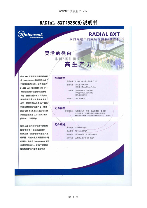
RADIAL RADIAL 88XT XT((63806380B B )说明书RADIAL RADIAL 88XT XT((63806380B B )说明书目录第一部分 设备电第一部分 设备电、、气及场地要求第二部分 设备机械组成部位介绍第三部分 设备安全标识及安全操作方法第四部分 设备第四部分 设备OS OS OS//2、IMUPS IMUPS系统介绍系统介绍第五部分 设备编程方法第六部分 设备机械部件调校方法第七部分 设备对第七部分 设备对PCB PCB PCB的工艺要求 的工艺要求第八部分 设备易损件表一>场地要求:1>电压:220+10VAC/55+10HZ 2>空气开关电流: 15-20A 3>机器功率: 2.7KW-3.4KW 4>气压: 90PSI 或6千克5>6>气管内直径: 13MM 7>电线要求: 4-6平方8>车间温度: 22-26度9>湿度:50-60%1>L1机头长:1.6M 2>L2机头宽:1.8M 3>L3机尾长(20站):1.6M (每增加20站增加1M)4>L4机尾宽:1.5M 5>L5整机长:3.2M 6>机器高度:1.7M7>机器两侧:M1`M2>1.0M 机尾M3>1.0M 机头M4>2.0M二>机器尺寸:第一部份 设备场地要求及电第一部份 设备场地要求及电、、气、机器尺寸第二部份 设备机械组成部位介绍1、分配头与链条2、计数器3、剪切站4、分配头5、分配头感应6、链条马达7、操作面板开头8、CTA部件8、X、Y轴定位系统9、BEC定位系统10、剪脚头14、元件抛料站11、插件头12、元件出现检测器13、修复元件指示灯第三部分 设备安全标识及安全操作方法一、二、8>生产中有紧急情况须按下急停开关等候技术人员处理7>严禁机器在无人操作下自动运行三、安全门感应器位置及安全操作注意事项3>机器生产中不可以碰到安全门 4>机器生产中不可拉开安全门5>生产中严禁在机器盖上放任何硬物或杂物 6>生产中严禁进入系统中修改参数 2>严禁两人操作一台机器各开关及按健 1>机器在生产中不可将手、工具放在移动台上Palm Switch 紧急停止安全门感应器安全门感应器安全门移动工作台移动工作台第四部分 设备第四部分 设备OS OS OS//2、IMUPS IMUPS系统介绍系统介绍将此开关转到ON位置,机器处于手动状态可进行维修保养或更换一、操作面板(各功能键位置)STOP 停止START开始PalmSwitch 紧急停止OVERRIDE/TRANSFER ERROR 连续运行INTERLOCK RESET 恢复联锁INTERLOCK BYPASS维修/手动/自动方式SYSTEM SETUP (系统设定):设系统各项参数PRODUCT EDIT(产品编辑):进入产品程序编辑PRODUCT CHANGEOVER(产品转换):从不同路径导入产品程序PRODUCTION CONTOL(生产控制):进入手动控制状态MACHINE STATUS(机器状态):显示当前机器所处状态MANAGEMENT INFORMATION(管理资料):记录显示产品生产报告 DOCUMENTS(资料):机器有关说明文件IM DIAGNOSTICS(系统诊断):进入控制系统各参数校正及故障检修二、电脑控制屏各功能键SETUP(IMUPS设定):进入IMUPS操作系统设定SECURITY(安全):进入密码设定MAINTENANCE INTERVAL SERVICE(保养进度):进入保养进度表SHUTDOWN(关机):机器不做生产时关闭系统OS/2 WINDOW(OS2窗口):进入DOS菜单TURN OFF ALARM(关闭警报):遇到有警报声需点击做消除机器做分解动作机器做单步动作机器做连续动作显示产品内容显示生产信息显示物料站位情况LOAD PRODUCT(导入产品):导入新产品程序CHANGE PRODUCT COUNT(改变产品数量):在生产中修改所须生产产品的数量 FILE MANAGER(文档管理):管理各种文档插件头已启动工作1>点击电脑上 2>在Requested Count 中设定产品数量,点击FullCycle3〉在Products defined 中选择产品程序,接着点击OK产品程序已导入4>确认物料已装好后,将各安全门、盖关好5〉旋开拉起开关灯灭,接着按6>待机器归零结束后,将待生产的PCB板放到机器夹具上,再次按机器开始工作自动插件LOAD PRODUCT 图标出现上图三、导入产品程序进行生产方法点击FULLCYCLE1>开机a>先打开UPS电源,按POWER ON开关b>将机器后面电源开关OFF转到ONC>待机器电脑出现Initializtion complete 后开机完成开关b>用鼠标点击图标,出现右边提示选择YES C>将机器后面电源开关ON转到OFFd>关闭UPS电源,按POWER OFF开关四、关机操作方法STOP停止START 开始Palm Switch 紧急停止OVERRIDE/TRANSFER ERROR连续运行INTERLOCKRESET恢复联锁INTERLOCK BYPASS维修/手动/自动方式第五部分 设备编程方法A>length:xxx B>width:xxx图二4>在Template选择Save As(输入名称)选择OK即可5>在Board Thickness中输入PCB板厚度(如下图)选择OK即可B >Width Width((元件实际宽度元件实际宽度):):):((XXX XXX))mmC >Height Height((元件高度元件高度))(XXX XXX))mm1 1> > > 选择元件种类选择元件种类选择元件种类((如LEDS LEDS- - - Rad Rad Rad))2 2> > > 进入进入进入Component Component Component进行如下操作进行如下操作进行如下操作((如下图如下图) )3 3>>设定 设定 Body infornation Body infornationA >Length Length((元件实际长度元件实际长度):):):((XXX XXX) ) ) mm mm第二步>进入主菜单Components 中点击 Database6241F主菜E >polarized components polarized components((元件极性元件极性):):):YES YES YES/+/-//+/-//+/-/NO NOD >lead diameter lead diameter((元件脚实际直径元件脚实际直径):():():(xxx mm xxx mmA> Product Nome中输入程式名B> board中选入PCB尺寸(UIC设备生产程序制作方法-设定的PCB尺寸) C>选择OK1>在主菜单中执行Product Product Product点击点击点击New New2>在Nnew Product Nnew Product Nnew Product 中执行以下操作中执行以下操作中执行以下操作((如下图如下图))C>在Y POS 中输入Y坐标(用卡尺量)D>在Theta 中输入插件时的角度(0/90/180/270)E>在hole span 中输入插件时元件跨度(用卡尺量)F>在depth stop 中输入插件时元件高度(用卡尺量)1>在主菜单Components omponents omponents中点击中点击中点击Lnsertion List Lnsertion List Lnsertion List((如上图如上图))2>在Lnsertion List菜单中执行以下操作(如上图)G>在anvil span offset 中输入03>完成以上步骤即做好一个元件,重复以上步骤依此做出PCB上需插件的元件(如下图A>在component ID 中选择要插件元件类型(如:跳线/电阻/二极管)B>在X POS 中输入X坐标(用卡尺量)第五步:设定元件物料站位Dispense Heads1>在主菜单中选择Dispense Heads2>在Dispense Head List中输入元件分配的站位序号(如下图)第六步:程式名优化(根据实际需要操作)1>在主菜单中选择Order中点击Optmization(如下图)2>在Optimizetion optione中选择双下操作来完成优化(如下图3>在主菜单中选择save即完成程序制作第六部分 设备机械部件调校方法一、二、三、四、五、六、七、八、九、十、十一、十二、十三、十四、十五、十六、十七、十八、十九、第七部分 设备对PCB的工艺要求一、PCB工艺边设计(设备单窗口打板设计参考):板边为8.00MM板宽≤407.00MM板边为5.0MMAAB B 定位孔直径3.0+0.05MM(或椭圆5.0×3.0MM)定位孔中心离PCB板右边缘(A)5.0MM、离PCB板外边缘(B)3.5MM定位孔直径3.0+0.05MM、定位孔中心离PCB板左边缘(A)5.0MM、离PCB板外边缘(B)3.5MM二、PCB工艺边设计(设备双窗口打板设计参考)板边为8.0MM板宽≤170.00MM板边为8.0MM板长≤508.00MM定位孔直径3.0+0.05MM(或椭圆5.0×3.0MM)定位孔中心离PCB板右边缘(A)5.0MM、离PCB板外边缘(B)定位孔直径3.0+0.05MM、定位孔中心离PCB板左边缘(A)5.0MM、离PCB板外边缘(B)3.5MM AB A B四、不规则的PCB板须合成规则PCB板设计:第八部分 设备易损件表。
GKCD智能开关测试仪说明书11页word
GKC-D智能开关测试仪使用说明书上海菲柯特电气科技有限公司目录一、概述 (1)二、使用注意事项 (1)三、仪器特点 (1)四、仪器的全套配置 (2)五、技术指标 (2)六、面板介绍 (3)6.1 按键 (3)6.2 按键说明 (3)七、菜单功能说明 (4)八、操作说明 (5)8.1 文件 (5)8.2 参数设置………………………………………………………………………5、68.3 测试 (7)8.4 查看 (8)九、测量线的连接与传感器的安装 (8)9.1 断口信号线与断路器连接 (8)9.2 传感器与断路器连接 (9)9.3 合/分闸控制线的连接 (10)9.4 外同步信号采样线的连接 (10)十、仪器测试 (11)十一、术语定义…………………………………………………………………………11、12一、概述智能开关特性测试仪依据中国电力行业标准DL/T846.3—2019执行制造的新款设备,采用国际最新的贴片元件及微处理器,抗干扰能力强,测试精度高,直接控制开关合/分动作,并快速准确地显示测量结果,还可打印各项测试数据和时间-行程(断口)特性曲线图、时间-电流特性曲线图。
该系列仪器显示windows菜单界面,具有智能化提示,操作简单,可省略说明书操作;具有COM 及USB接口,具备超大容量存储空间,仪器自身存储30组测试数据,连接USB可存储280组测试数据。
本仪器可用于各种电压等级的真空、六氟化硫、少油、多油、VSI负荷开关的机械特性参数测试。
测量数据稳定,接线方便,操作简单,品质卓越,是高压开关机械特性参数测试最方便的工具。
二、使用注意事项1.在使用仪器前,确定仪器接地。
2. 内部直流电源为短时工作的操作电源(220V,10A),如超出内部电源使用范围,请用外同步或外接电源。
3. 输出电源严禁短路。
4. 任何个人或单位未经本公司允许,请不要打开机壳,否则本公司将不负责维修。
三、仪器特点1.仪器可自动识别断口合、分闸状态,并根据参考断口状态提示相对应的合、分操作。
寺冈电子称设置和培训资料

上海寺冈电子称安装设置及培训资料------------上海寺冈电子称调试安装,故障处理!!!一.校验称重量(标定)标定是为了秤有一个准确的称重,方法如下:按4次方式进入Z模式:[置零]+3752---> [置零]+8715--->显示cal 00(零点标定)--->按*字打印键--显示calsp--->放置15kg砝码(待稳定)---> 按*字打印键---> 按置零保存--->等待数秒, 返回登录模式,出现> 移走砝码---> 标定结束--->退出--->关机--->开机* 标定之后应再将砝码分别置于秤盘的四角,查看是否无偏差,否则应重新标定!二.秤的初始化(国家版本设置)1.[置零]+3752--->[置零]+[自动]---> 3---> [打印]---> 1---> [打印]---> [打印] --->[打印]------>等待几秒[清除]---->等待几秒[M]---> [M]2.按4次方式进入Z模式:置零+8822--->按[3](代表中国)--->按[打印]键--->按清除--->按清除按*--->按×选择到15KG--->按*--->按*--->按清除--->按两下方式三.设置1.标签与打印纸间的切换在称重状态下,同时按下‘置零’+‘方式’屏幕上显示为标签格式,反之打印纸。
2.网络设置:置0+141,24×16*,25×16*,41×1*,42×0*,141×1*,142×1*,317×0*,49 ×2*,50×1*,135×称号*,按项目#保存,按"置零"+0416"设置该秤的IP,如果是设置2号秤的IP一般设为后面的002就是秤号;按"置零"+0418设置子网掩码一般改为:按项目保存3.精确到分:置0+3752 置0+142 629×0*#4.设店标n开头:置0+141 3×n*#5.设单个标签:置0+141 24×16*#6.设N位店内码:置0+141 8*#(4位),4*#(5位),5*#(6位1标识位),3*#(6位2位标识位)7.非称重:置0+141 41*0*#8.条码格式:编号+重量:置0+141 1×2*#9.条码格式:编号+价格:置0+141 1×1*#10.四舍五入:置0+3752 置0 142 629×4 *#3次M退出精确到2克,Z模式下,置0+3752;置0+142;646×1*;645×1(或者是0)*。
CAT Ⅳ 600 V 地线测量仪 FT6380、FT6381 用户指南说明书
CLAMP ON EARTH TESTERFT6380, FT6381For multi grounded systems onlyEasy pole earth resistance measurement with super slim jaw0.02 Ω to 1600 Ω wide measurement range for earth resistance measurement 1.00 mA to 60.0 A covering small leakage current to load currentEasy Open Jaw Light WeightHigh AccuracyPhone************Fax: 033 30222923************************0.87 inch(22 mm)2Get Things Done with Super Slim JawsEasy clamping!Open jaws easily with just two fi ngers.Only half the grip power is needed compared totypical clamp earth testers.Clamp at the narrowest point!Now you can easily clamp the earth cable on the polewithout digging. The dramatically slim 0.79 inch (20mm)jaws let you finish your job easily and effi ciently.No wait time after powering on.Start measuring instantly without zero-calibration.LCD with beautiful back lightWith the bright back light, you can easilyread the measurement value even in darklocations.Large storage capacity(up to 2,000 data)You can store up to 2,000 measurementvalues in the fi eld and recall them in youroffi ce later.Filter function enables evenmore accurate measurementsResistant mode filter: digital filter givesyou steadier readings.Current mode filter: Low-pass filtereliminates harmonics current over 180Hz. Quick Start!Alarm FunctionSet the alarm to audibly and visually notifyyou that the resistance or current valueexceeds the threshold.0.87 inchHigh Accuracy and RepeatabilityWell-designed magnetic shields eliminatethe leakage fl ux between the two cores thatoften affect measurement accuracy.1.5 inch1.26 inch(32 mm)(22 mm)(20 mm)(38 mm)Memory numbe r+++3Measurement PrincipleFT6380/6381 can measure Multi-Grounded systems.Voltage InjectionCurrent MeasurementRx R1R2R3R4Clamp on the earth cable. The instrument has two cores for voltage injection and current measurement.1. The voltage transducer injects a defi ned voltage into the multi-grounded system.2. From the defi ned voltage and measured current, the total circuit loop resistance is calculated in thefollowing equation.In a typical multi-grounded system, the parallel resistance value is small enough to be ignored and the equation as referredabove can be simulated as follows.Rx =VIAutomatic Report GenerationModel FT6381 can create reports instantly in the fi eld usingan Android TM phone via a Bluetooth® wireless technology.1111R1 R2 R3 R41Rx +VI=Offi ce. . .After making a report, you can see it onthe Android TM phone or send the datato your PC at the offi ce via e-mail.Real time data transferVia e-mailAutomatic Report Generationon your Android TM phoneReport includes the MeasurementValue, Date and Time, Map with GPSinformation and Pass/Fail information123Download dataAll information correct as of May. 22, 2012. All specifications are subject to change without notice.FT6380E2-25M Printed in JapanNote: Company names and Product names appearing in this catalog are trademarks or registered trademarks of various companies.Current ModeSpecificationsDisplayDigital/ LCD, max. 2000 digits Display update rate: 2 times / s Maximum conductor diameter formeasurementø 32 mm (1.26 in)Power supplyLR6 alkaline battery × 2Continuous operating time35 hours With display backlight off, Bluetooth OFF (FT6381)Auto power savePower save state when 5 minutes have elapsed since the last operation Operating temperature and humidity -10°C (14°F) to 50°C (122°F), 80 % rh or less (no condensation)Storage temperature and humidity (no condensation, except batteries)-20°C (-4°F) to 60°C (140°F), 80 % rh or lessDustproof and waterproof IP40 (EN60529) With Jaws ClosedTemperature characteristicsIn -10°C (14°F) to 50°C (122°F) range: add 0.1 × Measurement accuracy / °C Withstand voltage AC 7400 Vrms for one minute Between clamp sensor and casingMaximum input currentAC 100 A continuous, AC 200 A 2 minute (50 / 60Hz)Applicable standards Safety: EN61010 EMC: EN61326Dimensions, MassApprox. 73 mm (2.87 in) W × 218 mm (8.58 in) H × 44 mm (1.73) D , Approx 650 g (22.9 oz)AccessoriesCarrying Case×1, Resistance Check Loop×1, Strap×1, Instruction Manual×1Alkaline Battery(LR6)×2FT6381 InterfaceInterfaceBluetooth ® v2.1+EDRCommunication Distance 10 m (Class 2.1)Communication Protocol SPP (Serial Port Profile)CompatibilitySmartphone/ Tablet (Android TM )Applicable OSAndroid TM 2.1 or later Accuracy guaranteed for 1 yearResistance modeAccuracy guaranteed for 1 yearResistance Check Loop Carrying CaseAccessoriesBluetooth is a trademark of Bluetooth SIG, Inc. and licensed for use by HIOKI E.E. CORPORATION.Industrial Supply Syndicate54, Ezra Street, Kolkata - 700 001, INDIAPhone: 22350923, 22356676 Fax: +91 33 30222923Email:*******************************:。
施耐德电气 3A6382D 操作 零件手册 - GrindLazer
3A6382DZH操作/零配件GrindLazer™用于扁平混凝土和沥青表面物质的清除。
仅适合专业用途。
未获准用于爆炸性环境或危险场所。
GrindLazer 标准 RC71 EGrindLazer 标准 DC21 E重要安全说明请阅读本手册及磨床手册中的全部警告和说明。
熟悉操控装置并正确使用。
妥善保存所有说明。
目录23A6382D目录一般电动工具安全信息 . . . . . . . . . . . . 3警告 . . . . . . . . . . . . . . . . . . . . 4组件识别 . . . . . . . . . . . . . . . . . .6GrindLazer 标准 DC21 E . . . . . . . . . . 6GrindLazer 标准 RC71 E . . . . . . . . . . 7操作 . . . . . . . . . . . . . . . . . . . .8机器启动 . . . . . . . . . . . . . . . . . 8切割材料 . . . . . . . . . . . . . . . . . 8维护 . . . . . . . . . . . . . . . . . . .8零配件 - GrindLazer 标准 DC21 E . . . . . . .9零配件清单 . . . . . . . . . . . . . . . .9零配件 - GrindLazer 标准 RC71 E . . . . . . 10零配件清单 . . . . . . . . . . . . . . . 10技术数据 . . . . . . . . . . . . . . . . . . 11Graco 标准保修 . . . . . . . . . . . . . . . 13一般电动工具安全信息3A6382D 3一般电动工具安全信息警告阅读所有安全警告及说明。
摩托罗拉 MAX638Plus 车载对讲机 说明书
Privacy Plus TrunkedMobile RadiosA. Radio On/Off and Volume ControlB. Three LED IndictorsC. DisplayD. System SelectorE. Talkgroup SelectorF. Transmit Key (PTT)G. Microphone ConnectorCopyright InformationThe Motorola products described in this manual may include copyrighted Motorola computer programs stored in semiconductor memories or other mediums.Laws in the United States and other countries preserve for Motorola certain exclusive rights for copyrighted computer programs, including the exclusive right to copy or reproduce in any form the copyrighted computer program. Accordingly, any copyrighted Motorola computer programs contained in the Motorola products described in this instruction manual may not be copied or reproduced in any manner without the express written permission of Motorola. Furthermore, the purchase of Motorola products shall not be deemed to grant either directly or by implication, estoppel, or otherwise, any license under the copyrights, patents, or patent applications of Motorola, except for the normal non-exclusive, royalty fee license to use that arises by operation of law in the sale of a product.© 1996 by Motorola, Inc.All Rights Reserved.Motorola Malaysia Sdn. Bhd. (Company No. 12631DE),Bayan Lepas Free Industrial Zone, Phase III,11900 Penang, Malaysia.Printed in Malaysia.Motorola and Channel Scan are trademarks of Motorola,Inc.Contents ContentsGeneral Information . . . . . . . . . . . . . . . . . . . . . . . . . . . . . . . . 3 Functions Of The Buttons . . . . . . . . . . . . . . . . . . . . . . . . . . . . 4 General Operation . . . . . . . . . . . . . . . . . . . . . . . . . . . . . . . . . 5 Radio ON/OFF and Volume Control Knob. . . . . . . . . . . . . 5 Features And Advantages Of Trunking . . . . . . . . . . . . . . . . . . 6 Types of Tones. . . . . . . . . . . . . . . . . . . . . . . . . . . . . . . . . . 7 Modes of Operation . . . . . . . . . . . . . . . . . . . . . . . . . . . . . . 8 Display Icons . . . . . . . . . . . . . . . . . . . . . . . . . . . . . . . . . . . . . . 9 Display Character Summary . . . . . . . . . . . . . . . . . . . . . . . . . 10 Basic Operation . . . . . . . . . . . . . . . . . . . . . . . . . . . . . . . . . . 12 To Turn the radio On . . . . . . . . . . . . . . . . . . . . . . . . . . . . 12 To Receive. . . . . . . . . . . . . . . . . . . . . . . . . . . . . . . . . . . . 12 To Transmit On a Trunked System . . . . . . . . . . . . . . . . . 12 To Transmit On a Conventional System. . . . . . . . . . . . . . 12 To Monitor . . . . . . . . . . . . . . . . . . . . . . . . . . . . . . . . . . . . 13 Multiple System And Talkgroup Selection . . . . . . . . . . . . . . 14 Multiple System Selection . . . . . . . . . . . . . . . . . . . . . . . . 14 TalkGroup Selection. . . . . . . . . . . . . . . . . . . . . . . . . . . . . 15 Announcement Call . . . . . . . . . . . . . . . . . . . . . . . . . . . . . 15 Call Alert . . . . . . . . . . . . . . . . . . . . . . . . . . . . . . . . . . . . . . . . 16 Call Alert Decode . . . . . . . . . . . . . . . . . . . . . . . . . . . . . . . 16 Call Alert Encode . . . . . . . . . . . . . . . . . . . . . . . . . . . . . . . 16 Private Conversation . . . . . . . . . . . . . . . . . . . . . . . . . . . . . . . 18 Private Conversation Encode. . . . . . . . . . . . . . . . . . . . . . 18 Private Conversation Decode. . . . . . . . . . . . . . . . . . . . . . 18 Telephone Interconnect . . . . . . . . . . . . . . . . . . . . . . . . . . . . 20 To place a Call (Full Interconnect Capability). . . . . . . . . . 20 To receive a Call. . . . . . . . . . . . . . . . . . . . . . . . . . . . . . . . 21 SmartZone/AMSS Roaming Features . . . . . . . . . . . . . . . . . 23 SmartZone Operation. . . . . . . . . . . . . . . . . . . . . . . . . . . . 23 Site Lock/Unlock. . . . . . . . . . . . . . . . . . . . . . . . . . . . . . . . 24 Forced Site Search. . . . . . . . . . . . . . . . . . . . . . . . . . . . . . 26 Automatic Multiple Site (AMSS). . . . . . . . . . . . . . . . . . . . 26 Scan . . . . . . . . . . . . . . . . . . . . . . . . . . . . . . . . . . . . . . . . . . . 27 Introduction. . . . . . . . . . . . . . . . . . . . . . . . . . . . . . . . . . . . 27 Turning Scan On/Off. . . . . . . . . . . . . . . . . . . . . . . . . . . . . 271Contents2Programming/Viewing a Scan List . . . . . . . . . . . . . . . . . . 27 Nuisance Delete. . . . . . . . . . . . . . . . . . . . . . . . . . . . . . . . 29 Talkback Delay. . . . . . . . . . . . . . . . . . . . . . . . . . . . . . . . . 29 Off-Hook Suspend Scan. . . . . . . . . . . . . . . . . . . . . . . . . . 29Horn/Lights . . . . . . . . . . . . . . . . . . . . . . . . . . . . . . . . . . . . . . 30 Accessories . . . . . . . . . . . . . . . . . . . . . . . . . . . . . . . . . . . . . . 31 Important General Safety Information . . . . . . . . . . . . . . . . . . 32 Radio Care . . . . . . . . . . . . . . . . . . . . . . . . . . . . . . . . . . . . . . 35 Limited Warranty . . . . . . . . . . . . . . . . . . . . . . . . . . . . . . . . . . 36General Information3General InformationWith the MAX638 mobile radio you have made an excellent choice. Motorola offers high stan-dard of Motorola products. Y our MAX638mobile radio has left our factory only after extensive tests.radio works. Since standard operation may be changed by programming - both concerning the Functions which the radio includes and the But-tons used to activate them - the way your radio operates may differ from what is described here. If in doubt, contact the person in charge of your radioThe Ignition Cable Must Be Connected For Proper Operation. If Radio Ignition Cable Is Not Connected To The Radio, It Will Not Power Up.Functions Of The Buttons4Functions Of The ButtonsA. Radio On/Off and Volume ControlB. Three LED Indictors1. Tx: red led lights continuously when the radio trans-mits.2. Rx: yellow led lights continuously when the radio receives.3. Not usedC. Display with three "seven segments" characters.D. System Selectorbuttons. E. Talkgroup Selector enables selection of the talk-groups by pushing the talkgroup or talkgroup-buttons.F . Transmit Key (PTT) Push to talk, release to listen. G. Microphone Connectorbutton to turn the scanning On/ Off.turesPress thisbutton to exit a feature.General Operation General OperationRadio ON/OFF and Volume Control Knob Turn the radio on by turning the knob clockwise. The radio then carries out a self-test. Adjust the volume toa comfortable listening level by turning the knob (A)clockwise or counter clockwise as required.T urn the radio off by turning the knob (A) counter clockwise.error message, please contact the person in chargeof your radio system or your local service represen-5Features And Advantages Of TrunkingFeatures And Advantages Of TrunkingA trunked radio system allows a large number of usersto share a relatively small number of frequencies with-out interfering with one another. When a mobile opera-tor keys the microphone to establish communication with someone else in the system, the system automat-ically assigns a communication path - a repeater and its frequency. As soon as the conversation ends, the repeater becomes free for other users. Motorola Trunked Radio System has a central controller that does the automatic frequency assignment.Some of the key benefits of the overall Motorola Trunked Smartnet Radio System are:•No channel monitoring required prior to transmis-sion.•Fast channel access.•Automatic channel selection.•Privacy among members of the same group.•Uninterrupted conversations•Only one attempt is required to access the system.If all channels are busy, the call request enters aqueue and the central controller automaticallyassigns the next available channel.A high pitched "dih-dih-dit" tone sounds when the callcan be made.6Features And Advantages Of Trunking7Types of TonesType of T oneMeaning What to Do FAILSOFT Contin-uous faint “beep”every 10 seconds Operating under “failsoft” condi-tions. A system failure has occurred: the mobile is operat-ing on one channel in a conven-tional mode.Y ou can still transmit and receive, but you share a channel with other groups until the sys-tem is repaired.Disconnect Mode Warning Continuous illegalfunction “baaah”tone.Reminder to exit Phone or CallAlert Modes. Y ou may be miss-ing other types of calls.Press the Phone or Call button to exit the mode.Telephone Time-Out WarningHigh pitched 15-20second tone.Warning that the call will be ter-minated if not completed in 15 to 20 plete call or hang up. It is time up to finish your call or redial.Talk Prohibit Con-stant tone whenPTT is pressed.All unsuccessful attempts to access the trunked system.Try again, when you are in a bet-ter location.Busy Continuous“bah-bah-bah”when PTT ispressedAll available channels are busy and the radio is in queue.Release the PTT switch. Y ou will hear call back tone when it is your turn for a channel.TALK PERMIT orCALL BACKHigh-pitched “dih-dih-dit” tone signi-fying channel avail-ableNow you have a channel to access.The radio holds the channel open for about three seconds. Press the PTT and begin your transmission.VALID KEY HighPitched Chirp toneSignifies button press was accepted. Proceed with desired function. INVALID KEY“Bonk” tone whenbutton press isrejected.Inoperative feature or illegal but-ton press in current operating mode.Radio is not programmed for this function or exit a current operat-ing mode and access desired function.TIME-OUT -TIMERLow pitched, con-tinuous “baaah”.Present transmission will end in four seconds.Finish your transmission before your transmitter is disabled.Features And Advantages Of Trunking8Modes of OperationMode of OperationOther Calls which can be Received T ALKGROUP Announcement CallsPrivate Conversation CallsCall Alert PagesSystemwide CallsTelephone CallsANNOUNCEMENT TALK-GROUP All Talkgroup CallsPrivate Conversation CallsCall Alert PagesSystemwide CallsTelephone CallsPRIVATE Conversation Announcement CallsSystemwide CallsCall Alert Encode Announcement CallsSystemwide CallsTELEPHONE INTERCONNECTSystemwide CallsDisplay Icons9Display IconsThe display icons which appear on the display are:External Alarm SelectedScanningNot in UseProgrammingMonitorDirectDisplay Character Summary10Display Character SummaryThe MAX638 radio has a 3-character display. The character displayed on the left side of the display indi-cates type of incoming calls, while the other two char-acters displayed on the right side indicate current dispatch or conventional mode.•In trunking dispatch mode, the digit displayed in the middle indicates the system which can be any digit between 9 to 0 (0=system 10). The character dis-played on the right side indicates the talkgroup which can be any letter between A through P . •In conventional mode, both digits indicate the cur-rent conventional channel which can be any num-ber between 01 through 10.Self testWhen the radio is turned on, thisdisplay appears while the self test isin process.External AlarmThis display indicates horn andlights are and can be activated byCall Alert or Phone Call.Telephone InterconnectThis display indicates that you havereceived an incoming phone call.This display indicates that you haveanswered the incoming call or youare making a call.MonitoringThis display appears after you havepressed the Monitor button.Display Character Summary11Private Conversation CallThis display indicates you havereceived an incoming private con-versation phone call.Call AlertThis display indicates that you havereceived a Call Alert.This display indicates that you haveinitiated a Call Alert.FailsoftThis display indicates that the radiois in failsoft per talk-group mode.This display indicates that the radiois in failsoft per system mode.Basic OperationBasic OperationTo Turn the radio OnT urn the radio ON/OFF VOLUME knob clockwise. The last system that was prior to power-down will be dis-played.To Receivegroup by pressing talkgroup or talkgroup button until the proper talkgroup is shown. A conventional system will be indicated by digits only. A trunked sys-tem will be indicated by a digit and a letter.To Transmit On a Trunked SystemWhen the transmit Indicator LED lights steady or after the talk permit tones sound, press the PTT switch and speak into the microphone in a normal voice. If you hear tone(s) when you push the PTT switch, the sys-tem alerts you that certain conditions exist. Refer to the Alert T one table for explanations.To Transmit On a Conventional System The yellow indicator LED will light if any other unit is active on the channel. Do not transmit if someone else is using the channel. When you press the PTT switch located on your microphone, the Transmit indicator will light steady to indicate that "you are on the air". It will remain lit until the PTT switch is released.12Basic Operation13To MonitorWhen the radio is in conventional mode with coded squelch, the channel may be monitored by taking the(moni-TMultiple System And Talkgroup SelectionMultiple System And Talkgroup Selec-tionMultiple System SelectionThis radio has ten Systems, eight T alkgroups in each system, and ten Conventional Systems or Channels.MAX638 mobile radios allow the operator to select up to ten systems to be programmed into the radio. Each system may have its own unique set of talkgroups, Call Alert paging, and Private Conversation calls. After the system has been selected, there is a delay of about one second before the radio can receive or transmit calls.T runked Systems are identified as numbers 1 through0 (10). This trunked system number is always dis-played on the left of the display.Conventional Systems or Channels sequentially follow the last trunked system. However, conventional sys-tems appear as a number in the two rightmost digits.The indication that the radio is on a conventional sys-tem is seen when the display shows no letter or spe-cial character.14Multiple System And Talkgroup Selection TalkGroup SelectionA trunked radio system can divide a system into differ-ent talkgroups. This enables the system owner to organize the talkgroups into communication groups according to function. Members of a specific talkgroup hear only messages intended for their talkgroup.T alkgroups are identified as letters in the right most position on the display. The system is identified in the middle position. An extended press of the talkgroup button will scroll up the list. Press the PTT switch to transmit. The radio receives only those messages intended for the talkgroup indicated on the display. For example, if talkgroup B is selected, you will not receive messages for talkgroup E.Announcement CallIf the operator has a radio equipped with announce-ment call, it is possible to call all members in the talk-groups list (RSS programmable). If the operator is in announcement call mode and multiple talkgroups are active, only the first call received will be heard.15Call Alert16 Call AlertCall Alert DecodeThis feature allows an individual mobile unit in a sys-tem to receive a Call Alert or page from a dispatcher to leave a page in an unattended mobile unit. When the mobile unit receives the Call Alert, the display shows:This continues with beeps every four seconds until any key/PTT is pressed. Call Alert pages will not be received when the radio is engaged in voice conversa-tion, has been turned off, or is out of the system range.If your unit is equipped with optional horn/lights alert,see the description of Horn/Lights given on page 30. Call Alert EncodeThe Call Alert Encode Feature allows the dispatcher or supervisory unit to Call Alert or page up to eight mobile units.Tuntil the display shows: T o select a mobile ID from the ID list, press the talk-group or talkgroup button. Each mobile ID is identified as CA1 through CA8. Select the desired ID and press the PTT switch momentarily to send theCALL Alert.Call Alert17The radio will beep once to indicate that Call Alert has been sent. When the Call Alert has been acknowl-edged, the display will show:Then, the radio will sound four beeps and the displaywill automatically return to dispatch mode.pitch alert tone sounds and the display changes to show "nos". Y ou may try this sequence again whenAn illegal function tone will sound after six seconds of inactivity. This is to alert you that important channel(home) button orPrivate Conversation18Private ConversationPrivate Conversation EncodeThis feature enables a mobile unit to exchange privateT o select a mobile ID fro the ID list, press the talk-group or talkgroup button. Each mobile ID is identified as PC1, PC2, and so on till PC8. Select the desired ID and press the PTT switch to send the call. T o return to the last used talkgroup, press (home)button. Private Conversation DecodeWhen a Private Conversation call is received, two beeps are heard and the display shows:Private Conversation19(home) button.Telephone Interconnect20Telephone InterconnectY our radio is equipped with a telephone interconnect option that allows you to call land line telephones through the system. Calls made through the central controller are half-duplex operation (talk or listen). To place a Call (Full Interconnect Capability) If your radio is equipped with a DTMF microphone, you may place mobile-to-land calls. To initiate calls:If a free channel is available, the display will show:Y ou will hear dial tone. Select a phone number from the list by using talkgroup or talkgroup button.After selecting, the desired phone location, press the PTT switch. Y ou will hear tones as they are being sent out. When the desired number has been completely sent out, you will hear either a busy tone or ring tone. If•interconnect option has not been enabled and the telephone call cannot be made.Telephone Interconnect21•If radio is in queue and suddenly a constant out of range tone sounds, the system is not allowing any more interconnect calls.•After the called party answers, inform him/her that you are using a radio and that he/she must wait for the radio to finish transmitting (indicated by a soft beep) before replying. Proceed in a normal push-to-talk manner by pushing the PTT switch to talk and release to listen.•The maximum time period is determined by the traffic load of the System Central Controller. If a high pitch tone sounds, it alerts you that you have just 15 seconds to complete your conversation before the call will be disconnected.•Ttion "baaah" tone will sound after a short period. Other type of calls, except system-wide calls, will not be allowed while the telephone interconnect is engaged.To receive a CallA standard telephone Interconnect Receive features are as follows:•When a landline subscriber wants to call a particu-lar radio, he/she should dial the interconnect termi-nal phone number. If a line is free, the landline subscriber will hear a phone ring tone and the dis-play will show:to indicate a received call.Telephone Interconnect22TPress the PTT switch to talk and release to listen. •Tton.•If a mobile unit is equipped with the Horn/Lights feature, engage it before you leave the vehicle.When a call is received, the vehicle's horn will sound or the lights will flash for six seconds.SmartZone/AMSS Roaming Features SmartZone/AMSS Roaming Features SmartZone OperationRadios that operate in a SmartZone system will enjoy the benefits that SmartZone offers over AMSS opera-tion. SmartZone is a wide-area coverage system that will allow up to 50 sites to be operational in the sys-tem. SmartZone brings several enhancements over AMSS operation such as:•Dynamic Site Assignment - Allows the zone con-troller to dynamically assign channels at siteswhere required, as opposed to bringing up chan-nels at all sites as AMSS systems do.•Variable Density - Allows sites to have varying num-bers of channel resources to accommodate low-density areas as well as high density areas.•Automatic Site Registration/Deregistration - Smart-Zone radios automatically send in their unit IDs andcurrent mode selections upon power up, powerdown, site switches, talk group changes and whenthey exit emergency operation. This allows thezone controller to know where the radio is at alltimes and also what talkgroup the radio hasselected.•Enhanced FailSoft Operation - If a site experiencesa complete failure, it will revert to failsoft operationlike today’s SMARTNET system. A SmartZoneradio, however, can be programmed in the list ofcontrol modes. The radio will periodically scan thecontrol mode to check for the presence of a validcontrol mode (in case the radio roamed into a sitewhich is trunking.)23SmartZone/AMSS Roaming Features24•Locking and Unlocking a Site - As in AMSS, you can force the radio to stay locked onto a site. Y et you can still force the radio to scan to another site while the site is locked. The radio will automatically become site locked to the next site it finds.•Site Switching in SmartZone - When the radio (unlocked state) is out of range, it will automatically scan for a new site from list of 32 channels.Site Lock/Unlock•If the radio is programmed to include SmartZone orAMSS, it requires to designate the site from which itshould start operating on the system. To do so,choose the proper mode from the mode list.•In the unlocked mode (automatic roaming), theradio switches between the repeater sites as onegoes out of range and another comes within range.In the locked mode, the radio will remain on the cur-rent site even if you go out of range of that site.When you are in Site Unlocked Mode and want to change to Site Locked Mode.•shows:•SmartZone/AMSS Roaming Features25When in Site Locked Mode and you want to change to Site Unlocked Mode.•shows: •abling the automatic roaming functions of the radio. If you are unsatisfied with the coverage chosen by the automatic site selection of the radio, we recom-mend that you use the Forced Site Search feature instead of Site Lock to gain improved coverage at aSmartZone/AMSS Roaming Features26 Forced Site SearchWhen you are in a poor coverage area and are not sat-isfied with the automatic site selection of the radio, you can activate the Forced Site Search function to scan for a new site.The "Forced Site Search" feature can be activated in Site Lock or Site Unlock Mode and is enabled as fol-lows:•shows:•A forced search can be activated during normal opera-tion as well as during Call Alert, Private Conversation,Phone.Automatic Multiple Site (AMSS)Automatic Multiple Site Selection (AMSS) feature is available either in the automatic (unlocked) or manual (locked) mode. In the automatic mode, the radio switches as one goes out of range and the other comes within range. In the manual mode, the site used is the site that is selected when you have entered the manual mode. A forced site search (FSS) can be initi-ated either in the automatic or manual mode.Scan27ScanIntroductionThe scan feature allows you to monitor activity on dif-ferent conventional and trunked modes by scanning a "scan list" of members (up to 8 members).Turning Scan On/Off(scan) button when in any system/(scan) button.For as long as "SCAN ON" is selected, the (icon will be displayed and the radio will scan for activity in the channels/talkgroups that are defined in the scan lists of the present mode.Programming/Viewing a Scan ListMAX638 allows front panel programming to allow the operator to edit the scan list.Scan28The radio will sound four quick beats and the display will show:When in scan programming, use the talkgroup but-ton or talkgroup buttons to scroll through the talk-groups.Tdisplay will show:(home) button. The display will show the home dis-A scan list is limited to eight members. A alert tone sounds if you attempt to add more than eight mem-bers.If you select a talkgroup as a priority and there is already a priority talkgroup in the scan list, then the new talkgroup will be assigned as the priority talkgroup and the old talkgroup will become a non-priority talk-group.Scan29Nuisance Deleteo and reenter scan mode. Talkback DelayY ou may talkback during a detected activity for a pre-programmed (RSS) time period after the activity ends.After this time period, the radio will resume scan. Off-Hook Suspend ScanIf this feature is enabled (RSS programmable), the radio will stop scanning when the radio is off-hook.Scan will be resumed when the microphone is replaced on-hook.Horn/Lights30Horn/LightsWhen you are outside the vehicle, your horn/lights fea-ture will activate the vehicle's horn/lights (if enabled)upon receiving an incoming call alert or land to mobile phone calls.Tbutton until the display shows:T o disable - press any key.Accessories AccessoriesPlease contact your local Motorola representative for further information about the accessories listed below: Microphone Options:•Palm Microphones•Keypad Microphones (DTMF)Mounting Accessories:•Key Lock•Direct T runnion MountExternal LoudspeakerA Variety of Cable kits (power, ignition, etc.)•Power•IgnitionAntennas31Important General Safety InformationImportant General Safety Information Read This Information Before Using Your Mobile RadioFor the safe and efficient operation of your mobile, observe these guidelines.Y our mobile is a radio transmitter and receiver. When the mobile is ON, the externally mounted antenna is the part of the mobile that sends out and receives radio frequency (RF) energy.•Exposure to Radio Frequency EnergyIn 1991 the Institute of Electrical and Electronics Engi-neers (IEEE), and in 1992 the American National Standards Institute (ANSI) updated the 1982 ANSI Standard for safety levels with respect to human expo-sure to RF energy. Over 120 scientists, engineers, and physicians from universities, government health agen-cies, and industry, after reviewing the available body of research, developed this updated Standard. In March, 1993, the Federal Communications Commission (FCC) proposed the adoption of this updated Stan-dard. To operate within this updated ANSI Standard, use your mobile as described under "Efficient Mobile Operation".Efficient Mobile Operation•DO NOT operate your mobile when a person iswithin two feet (0.6 meters) of the antenna unlessthat person is shielded from the antenna by a metalsurface such as the roof of the car. Otherwise youmay impair call quality, may cause your mobile tooperate at a higher power level than is necessary,and may expose that person to RF energy inexcess of the levels established by the updatedANSI Standard.32。
三通道测振仪VM-6380-3操作和维护手册说明书
三通道测振仪VM-6380-3操 作 和 维 护 手 册使 用 说 明 书显示器:4位液晶显示器,用于显示数值和测量状态传感器:三个压电式振动传感器测量参数:速度、加速度及位移测量范围:速度:0.01-400.0 mm /s 真有效值0.004-16.00 inch/s 加速度:0.1-400.0m /s ² 峰值0.3-1312 ft/s ² ; 0.0-40g 位移:0.001-4.000mm 峰-峰值0.04-160.0 mil 准确度:±(5%n +2)个字输出:交流2.0V ,负载电阻10K关机: 2种模式,手动可随时关机,自动则在上次键盘操作5分钟后自动关机。
操作条件: 温度0-50℃ 湿度: < 95%尺寸: 140 x 73 x 35 mm 电源:4x 1.5vAAA 7#电池重量: 415 g (不含电池)标准配件:1. 磁性吸座........................1块2. 压电式振动传感器......... 3只3. 探针(锥型)……............1只4. 探针(球型)…...........….1只5. 手提便携箱.....................1只6. 使用说明书.....................1份可选配件:1. 耳机听诊器2. RS 232C 或USB 电缆和软件3. 蓝牙* 符合国际标准ISO 2954,GB 13823.3,用于周期性运动测量,以检测运动机械的不平衡和偏离。
* 专为现场测量各种机械振动而设计,以便为质量控制,运行时间及事先的设备维护提供数据。
* 选用高性能的三个压电加速计,可实现三维振动测量,准确度高、重复性好。
* 它具有轴承状况测量功能。
* 液晶LCD 显示,一个显示器可以同时显示三个测量点上的同一参数,或者任意一个测量点上的三种参数(加速度,速度,位移)。
* 重量轻,且操作简单,便于使用。
- 1、下载文档前请自行甄别文档内容的完整性,平台不提供额外的编辑、内容补充、找答案等附加服务。
- 2、"仅部分预览"的文档,不可在线预览部分如存在完整性等问题,可反馈申请退款(可完整预览的文档不适用该条件!)。
- 3、如文档侵犯您的权益,请联系客服反馈,我们会尽快为您处理(人工客服工作时间:9:00-18:30)。
振动
:<100Hz
冲击
:2G
环境温度 :-30℃~+70℃
相对湿度 :<95%
转速微调 :标定转速±200Hz
3.组成及工作原理
控制器的组成如图一所示。
它的工作原理是:首先接收来自磁电传感器的转速信号,经过处理和转换
后,与参考信号进行比较,产生出误差信号。该误差信号再经过 PID 运算形成
调整电压,该调整电压被放大后驱动执行器完成对转速的控制。
到此设定值时,绿色的 LED 指示灯亮,同时输出继电器开关信号。该信号可 作为其它自控装置的辅助信号。 电瓶低电压告警指示
当电瓶的输出电压在发动机启动瞬间下降到 18V 以下时,红色的 LED 电 压指示灯亮,表示电瓶的电量不足,但发动机仍有可能启动。此时应给电瓶 充电,或者更换新电瓶。告警状态在控制器断电后自动恢复。 高速起车(额定转速)
5.2.4 状态调整
状态调整稳定的原理和增益、稳定调整不同,状态开关 SW1 是通过其位置
变化产生选频作用,该作用可有效地抑制发动机工作时系统内部产生的高频振
荡。状态开关 SW2 的不同位置决定了控制系统微分作用的大小,由此能改善和优
当辅助装置与端子 13 进行接线连接时,转速会降低,发动机转速必须重 新设定。 5.控制器安装调试 5.1 控制器安装
转速控制器应安装在无强烈冲击振动及电磁干扰的防护箱内,并需留有足 够的空间供安装维护和散热之用,其外壳需可靠接地。垂直安装可防止水气过 多驻留。
转速控制器安装尺寸如图二所示。 5.2 控制器参数调整 5.2.1 控制器接线图 应用于发电机组时接线如图二,全程调速接线如图三。 5.2.2 初次启动 检查供油杆灵活性,此项检查非常重要,要求整个供油行程无卡滞,如果供 油杆不灵活,就意味着控制器的控制性能降低,严重时出现控制失灵,从而 造成发动机转速不稳,超速等严重故障。 按图二要求检查相关电气连接是否正确。 检查执行器动作灵活情况。确定连接灵活后,再检查执行器动作最小位置应 能断油(气),最大位置应能达到最大供油(气)量。 检查电瓶电压,空载时应大于 24V,启动瞬间不低于 18V。
安装维护方便,可靠性高。该产品适应于控制各型发动机。
2.主要技术参数
电源电压
:12V 或 24VDC
功耗
:<80mA(静态)
输出电流
:<8A
转速波动率 :±0.25%
高速设定范围 :1K~7.5KHz
转速信号
:0.5~120VRMS
温漂
:<±0.5%
稳态调速率(速降):0~5%
电瓶低电压告警 :<18V
怠速值,则需重新调整低速设定电位器。顺时针调节增加转速,逆时针调节 降低转速,直至达到所要求的怠速。
拨动高低速开关使发动机从低速升到高速运转。观察转速表指示,调整 高速电位器使转速达到额定转速。顺时针调节增加转速,逆时针调节降低转 速。
在怠速和高速值设定后,要仔细观察转速的波动率。若超过±0.25%,发 动机出现游车,或者出现快速不稳定,则按下述稳定性调整方法将转速调整 到满足要求。
发动机标定转速可能需要重新设定。
启动油量限制
启动油量随发动机启动环境温度而变化。通过调整启动油量电位器,可
调整发动机的启动排烟至最佳。
升速时间控制
调整该电位器可以控制发动机从怠速至额定工作转速的升速时间,顺时
针旋转增大,逆时针旋转减小。
超速保护
调整超速设定电位器可以设定超速限制点,当发动机转速超过限制点时,
超速保护电位器顺时针旋转速度升高,逆时针旋转速度降低。具体步骤 如下:
第一、顺时针旋转超速电位器 3~5 圈。 第二、使发动机在额定转速下运行(一般为 1500 转/分)。 第三、调高速电位器至额定转速的 1.1 倍(1650 转/分)。 第四、逆时针缓慢旋转超速电位器,至超速指示灯亮,同时发动机停车, 实现超速保护。 第五、按动超速复位按钮,逆时针旋转高速电位器 1 圈,然后重新启动 发动机。 第六、调高速电位器至所需的额定转速。至此设定完成。 如需对超速保护值进行验证,可调高速电位器使额定转速增高,直至发 动机产生超速保护。再回调高速电位器至额定转速。 稳定性调整 稳定性的调整顺序是先低速、后高速、再加满载,使三种状态下都达到 稳定。 稳定性调整主要通过增益、稳定电位器调节完成。增益电位器是用来调 节调速系统的灵敏度,顺时针调节增大灵敏度,逆时针减小。稳定电位器是 用来调节调速系统的响应时间,顺时针调节增加响应时间的速率,逆时针减 小。通过增益和稳定调节可以使发动机状态至最佳。 注意:低、高速和带载的稳定性相互有关联,调整时要三者兼顾,使系统三 种工况稳定性都达到最佳。在以上稳定后增益应尽量偏大,以保证动态指标 最佳。 稳定性调整步骤如图五所示。
控制器输出被切断,执行器断电,发动机停车。同时控制器输出跳闸开关信
号且红色 LED 指示灯亮,该跳闸信号可用来控制其它外部防超速装置(如断
油或断气装置)。当发动机停车后,通过按下超速复位按钮或断开控制器电源,
可使控制器恢复正常。
全程调速
按图三在端子 7、9、10(11)间接一个电位器,可以实现全程调速。顺
高速和低速在出厂时已设定,一般该值与用户发动机工作转速值基本接 近。实际使用时只需少量调整即可达到要求值,而且稳定性相当好。 启动油量(烟度)调整
大同市云四达科技有限公司
把高低速开关拨到低速位置,使发动机处于低速状态。调整低速电位器 至所需怠速。此时,逆时针调整启动油量电位器,直至发动机转速开始下降, 再回调到怠速稳定为止。然后停车重新启动。如发动机启动困难,可增大启 动油量。
高低速开关用于低速控制与标定转速控制的切换。外接转速微调电位器
可精细调节转速偏差。
自动停车保护
当转速传感器发生故障,转速反馈信号消失,或电源掉电时,该功能可
使发动机自动停机。
稳态调速率(速降)可调
控制器的稳态调速率根据实际需要可设置为可调与不可调。把端子 10、
11 接通,调速率为可调。顺时针旋转速降电位器,稳态调速率增大。此时,
启动油量受环境温度影响,为了使发动机便于在各种气候条件下启动, 应将启动油量电位器设置到偏大位置。 升速时间调整
用户可根据需要调整升速时间电位器,确定从低速升至额定转速所需的 时间。逆时针旋转,时间缩短;顺时针旋转,时间延长。工作状态下可在 3 到 50 秒内任意调整。 超速保护设定
一般情况下,在出厂时超速保护已按用户提供的发动机型号设定,无需 用户调节。如用户需要设定,则按下列步骤进行。
时针旋转转速增高,反之降低。转速调整范围由电位器的电阻大小决定,见
下表。使用该功能时,高速电位器位置应在中间位置。
转速调整范围
电阻值
900 Hz
1KΩ
2400Hz
5KΩ
3000Hz
10KΩ
3500Hz
25KΩ
3700Hz
50KΩ
大同市云四达科技有限公司
转速信号输出 调整转速输出设定电位器,可以设定任意转速输出值,当发动机转速达
1.概述
FSK638D 发动机电子调速控制器具有调速精确快速、最大电流限制与保护、
稳态调速率可调、高低速设定范围宽、启动油量限制、升降速时间控制、电瓶
低电压告警指示、超速保护、启动成功转速信号输出、自动并机等功能。它的
工作原理是将控制器和电磁执行器、磁电传感器等构成闭合控制回路,从而完
成对发动机宽范围的速度控制。和其它控制器相比,其调速性能好,功能齐全,
第二、调节稳定电位器。顺时针旋转稳定电位器,若不稳定增加,则逆
时针旋转直至出现稳定。若没有稳定点,旋转电位器至相对稳定处。
反复上述两个步骤,优化调节,一般可达到稳定。若仍不稳定,继续下
面步骤。
第三、调节状态开关。详见 5.2.4。
调节状态开关后,重复第一、第二调整步骤。若通过上述调整仍不能达
到稳定,则应检查发动机和油泵等的工作情况。再者与厂家直接联系。
5.2.6 调整注意事项………………………………………………..….10
6.调速系统故障维修指南………………………………………….……10
6.1 常规故障检查…………………………………………………..…..10
6.2 故障诊断表………….………………………………………….......10
大同市云四达科技有限公司
再重新调整高、低速电位器,达到要求的转速值。
调试窗口中各调整元件位置如图四所示。
高速 转速 超速 W7 W102 W101
稳定 W4
状态 SW2
ON
0123 ON
123
W5
W2 W6 W1
升速时间 低速 启动油量 速降
图四 调试窗口示意图
W3 SW1 增益 状态
高低速调整 把高低速开关拨到低速位置,启动发动机。工作后,若发动机转速偏离
大同市云四达科技有限公司
FSK638D
发动机电子调速器
控制器
使用说明书
大同市云四达科技有限公司
大同市云四达科技有限公司
前言 本使用说明书主要介绍了电子调
速器的正确安装、校正、调节、操作 以及维护方法等,它适用于电子调速 器进行安装、连线、使用和日常维修 的人员。建议将本手册存放于产品的 工作场所。使用该产品时,应遵循这 里所提供的方法去操作。
本控制器可在高速下直接启动,此时发动机会由低速上升至高速。其升 速时间可由升速电位器调节。 并机功能
端子 13 接收来自负载分配装置、自动同步装置和其它调速器系统辅助装 置的输入信号。该装置直接与端子 13 连接,其接线应屏蔽。
如果单独使用自动的同步装置而不与负载分配组件连接在一起时,端子 13 和 14 之间应连接一个 3MΩ 的电阻。这主要是为了在转速控制装置和同步 装置之间进行电压匹配。