Iomega_ix2-200培训材料
焊锡测试组装培训

28
点胶机概述
深圳西卡姆同位素有限公司 Shenzhen CICAM Manufacturing Co. Ltd.
适用流体: 各种溶剂、固体胶等,包括硅胶、密封胶、灌注胶、橡胶等等。 工作原理: 压缩空气送入胶瓶(注射器),将胶压进与活塞室相连的进给管中,当活塞处于上冲程时,活塞室 中填满胶,当活塞向下推进滴胶针头时,胶从针嘴压出。滴出的胶量由活塞下冲的距离决定,可以 手工调节,也可以在软件中自动控制。
ICP2-GANG
ICD3
MPLAB MP3
HOLTEK
3、电脑 电脑与烧录台和烧录器相连接,进行程序烧录。
12
ESD防护要求
深圳西卡姆同位素有限公司 Shenzhen CICAM Manufacturing Co. Ltd.
工作台面必须铺防静电胶皮,并与ESD人体接地线相连,ESD人体接地线不可与设备接地线互 连;
其他品质及培训资料
烟箱校机作业规范
29
点胶作业规范
校机设备简介
深圳西卡姆同位素有限公司 Shenzhen CICAM Manufacturing Co. Ltd.
烟雾探测器校机烟箱: 1000系列烟箱主要基于一个薄钢板制成的循环管道,并以一个透明有机玻璃门与检测区间相连 。烟箱设计符合空气动力学原理特征,能够在 0.2米/秒 到 1.0米/秒 之间的气流下保持正常非扰动运 转。 在烟雾检测时,带有实时显示气流速度的气流速度传感器可作为包含选项之一。 烟感烟箱使用自带气溶胶发生器,产生符合EN54-7的石蜡气体。气体浓度由同样符合EN54-7要 求的AW Technology科技有限公司研发的光学密度计进行测量。
【全套精品课件】S7-200PLC基础教程第2版电子教案讲述

2.5 编程软件概述
2.5.1 软件安装与项目的组成 1.软件的安装 2.项目的组成 (1)程序块:主程序(OB1)、可选的子程序和中断程序。程序结束时不需 要加入无条件结束或返回指令。 (2)数据块:用于对V存储器赋初值,由数据和注释组成。 (3)系统块:用来设置系统的参数,一般可采用默认的参数值。
CPU 224XP:2AI、1AO,2通信口,高速输入200kHz、高速输出100kHz。 PPI、MPI、自由通信口协议和PROFIBUS点对点协议; 使用STEP 7-Micro/WIN编程软件。 2.3.2 数字量扩展模块 数字量I/O:8DI、16DI、4DO、8DO、4/4、8/8、16/16、32/32DI/DO。 输入有24V DC和230V AC两种,输出有24V DC和继电器型。 2.3.3 模拟量扩展模块与热电偶热电阻扩展模块 模拟量模块的作用:A/D转换与D/A转换。 模拟量I/O:12位4AI、2AO、4AI/1AO;15位4路热电偶、2路热电阻模块。 模拟量输入模块有多种量程(与模块型号有关),用模块上的DIP开关设置量 程。
P (6000) 6000 (6000) N 6400 32000 6400
P 12000 120 ( N 6400) 6000 ( N 6400) 6000 (0.1Pa) 25600 256
20mA +600Pa P
4mA 0mA
-600Pa 0 6400 N 32000
2.8.4 其他参数的设置 1.脉冲捕捉功能 2.后台通信时间
2.9 S7-200仿真软件的使用
1.仿真软件 不需要安装,不能模拟S7-200的全部指令和全部功能。 2.硬件设置 执行菜单命令“配置”→“CPU型号”,选择CPU的型号。 双击紧靠已配置的模块右侧的方框,可添加I/O扩展模块。 3.生成ASCII文本文件 在编程软件中打开编译成功的OB1,执行菜单命令“文件”→“导出”。 4.下载程序 5.模拟调试程序 如果用户程序中有仿真软件不支持的指令或功能,点击【运行】按钮后, “RUN”LED的状态不变。 用鼠标点击模块下面的小开关产生输入信号。 6.监视变量 执行菜单命令“查看”→“内存监视”,在出现的对话框中,可以监视V、 M、T、C等内部变量的值。用二进制格式监视字节、字和双字,可以在一行 中同时监视多个位变量。
M200&M100 硬件培训手册
2.12.1.1 外部输入中断功能 ............................................................................................26
பைடு நூலகம்
2.12.1.2 快速计数器(FC)功能 ....................................................................................26
2.13 QR 码使用 ...............................................................................................................31
Page 3
Modicon Easy M200&M100 plc
SCHNEIDER ELECTRIC
Modicon Easy M200&M100 plc
培训手册
硬件篇
Patrick DUAN jiyong 2014.9
Industry Offer China
Page 1
Modicon Easy M200&M100 plc
培训手册
目录
1 概述 ..............................................................................................................................4 1.1 产品特色....................................................................................................................4 1.1.1 恰好满足你的需求..................................................................................................4 1.1.2 产品的易用性 .........................................................................................................7 1.1.3 增强的产品性能 .....................................................................................................7 1.2 产品使用环境特性 .....................................................................................................8 2 硬件概览 .......................................................................................................................9 2.1 硬件组成....................................................................................................................9 2.2 模块安装特性...........................................................................................................10 2.3 CPU 模块特性 .........................................................................................................11 2.4 CPU 特性指标 .........................................................................................................12 2.5 供电特性..................................................................................................................15 2.6 RTC 实时时钟 .........................................................................................................16 2.7 SD 卡.......................................................................................................................17 2.8 LED 显示 .................................................................................................................18 2.9 正面扩展板 ..............................................................................................................20 2.10 右扩展模块 ..............................................................................................................20 2.11 通讯接口..................................................................................................................21
发那科培训

开机后利用各个界面做备份
1、CNC参数
2、PMC 程序
? 1、按下system ? 2、按拓展键找到梯形图 ? 3、按下操作 ? 4、按执行
3、PMC参数
? 1、按下system ? 2、按拓展键找到梯形图参数 ? 3、按下操作 ? 4、按执行
4、螺距补偿
5、宏变量6、刀具补偿7、加工来自序利用BOOT 界面做备份
急停回路
CNC单元接口
电 池
1、CNC为3V[BAT] 零件的程序,偏置量和系统参数存储在控制单元的 CMOS 存储器中。 其后备电池是安装在控制单元前面板上的锂电池。上述数据在主电源 切断时不会丢失。后备电池在出厂前就已经安装在控制单元中,用后 备电池可以使存储器中的内容保存一年。当电池电压降低时,在 CRT 上就会出现 “BAT”字样的系统报警,并且电池报警信号输出给PMC。当这一报警信息出现时,请 尽快更换电池。通常,电池应该在2-3 周内更换完成。
? F7.0、F7.2、 F7.3发出信号
? G5.0、G5.2、
G5.3置零执行 结束
? M、S、T
IOlink分配
? 理解组、座、槽
PMC使用
功能指令P165
? @了解C、T的编号及数值具体 是多少 P235
PS:另一种做法:在启动界 面利用ROM内做,文件名不
能更改
梯形图的编辑(P265)
fanuc0ID培训讲义
1、硬件连接 2、系统工作通道 3、I/Olink分配 4、数据备份 5、PMC程序应用
1、硬件连接
硬件主要组成部分 1、CNC 2、电源模块( 364) 3、伺服放大器 4、伺服电机 5、IOlink板路
一体式(βI系列)
分体式(αI系列)
Image Perfect E.P-200 操作手册说明书

PNEUMATIC MACHINE TO SET EYELETSAND WASHERSIMAGE PERFECT MODEL: EP - 200OPERATING MANUALINDEX1INTRODUCTION (3)1.1INTRODUCTION (3)1.2MACHINE IDENTIFICATION AND “CE” MARKING (3)2TECHNICAL DATA (4)2.1MACHINE SPECIFICATIONS AND OPERATION (4)2.2MAIN TECHNICAL DATA (4)3INSTALLATION (5)3.1INSTALLATION POSITION REQUIREMENTS (5)3.2PENUMATIC INSTALLATION (5)3.3TRANSPORT (5)3.4UNLOADING AND LEVELLING (6)3.5LIGHTING CONDITIONS (6)3.6LEARNING INSTRUCTIONS (6)4MACHINE OPERATION (8)4.1MACHINE DESCRIPTION (8)4.2CHECKING THE MACHINE BEFORE STARTING (8)4.3EYELET SETTING (8)4.4OTHER MACHINE APPLICATIONS (9)5ADJUSTMENTS (10)5.1WARNINGS ABOUT THE ADJUSTMENTS (10)5.2DIES CHANGING (SAME OR DIFFERENT EYELET DIMENSION) (10)5.3SAFETY RING ADJUSTMENTS FOR DIFFERENT THICKENES.........Error! Bookmark not defined.6MANTEINANCE (13)7FAILURES (14)7.1TROUBLESHOOTING (14)8SAFETY (15)8.1SAFETY DEVICES (15)9ANNEX (16)9.1SPARE PART LISTIG (16)9.2SUPPLIED TOOLING (16)9.3PNEUMATIC DRAWING (16)9.4GUARANTIES (17)1INTRODUCTION.1.1INTRODUCTION.This machine has been designed to set eyelets and washers, making in just one operation the cutting and setting. This unit has been specially manufactured to set Image Perfect plastic eyelets.EP-200 can set eyelets on materials such us PVC coated material and in general terms on plasticized fabrics. It will not work on fabrics as cotton or polyester.The standard eyelets holes are Ø8, Ø12 and Ø16 mm.1.2MACHINE IDENTIFICATION AND “CE” MARKING.Each machine has a data plate on the side, made on aluminum. The following specifications are on it:-Manufacturer’s name and data.-Year of production.-Model and serial number.-Maximum air pressure (in bars).-“CE” mark.-Weight.2 TECHNICAL DATA.2.1 MACHINE SPECIFICATIONS AND OPERATION.The machine consists on a metal head where all the parts are placed (fix and moving ones), such us pneumatic cylinder, axle, setting dies, safety devices, etc and a pneumatic pedal.This unit has been designed to bolt it to the customer’s work bench. EP-200 can be also mounted on a plastic (PE) table with four wheels (MIPEP202) on the corners, all of them with breaking system. Installing EP-200 on wheels can help to move the eyelet-press around large banners.Once the machine has been place on its permanent location, without fitting the air hosepipe into theconnection, verify that it has not suffered any blow or breakage while being transported and it has not any loose parts.The operation of the machine is very simple:1. Operator will open the air inlet valve “A”, placing manually the eyelet through the top die “B” andwasher on the bottom die “C” and then put the banner over it.2. When pressing down the pedal “D”, a pneumatic cylinder is set in motion, making the safety ring “E”to come down up to the safety height preventing the access of operator’s hands to the setting area “X” and activates the micro end of race which sets the main pneumatic cylinder in motion.3. The axle of the main pneumatic cylinder “F” will come down. Attached to its lower part, there is thetop die “B”. The aim of the downward movement of the axle is to cut a hole on the material with the top die and as an effect of the pressure that the top die “B” puts on the bottom one “C”, to roll the eyelet over the washer.4. After the eyelets is set, all parts will return to its starting position, leaving the machine ready foranother cycle as soon as we place again the eyelet, washer and banner2.2 MAIN TECHNICAL DATA.The main technical data of this machine are:Width x Depth x Height 24 cm x 32 cm x 41 mm. Weight28,5 Kg / 63 Pounds. Air pressure 6 bars / 87 psi.(E) (B) (C)(A)(F)3 INSTALLATION.3.1 INSTALLATION POSITION REQUIREMENTS .The minimum space recommended must be sufficient to keep that safety space in all directions for the operator to work properly.3.2 PNEUMATIC INSTALLATION.The machine has an air inlet valve, type quick acting coupler (ISO 6150-B standard) ∅8 mm , located in the back of the machine (A).Fig. 2For an optimal operation, the supply of compressed air should be 6 Kg/cm 2. It is important, especially when working with Ø16mm eyelets that the pressure doesn’t drop after one of two settings as the machine might not have enough power to close the eyelet. If this happens you will require a bigger compressor with more power.We recommend that the flexible air hosepipe from the compressor or pneumatic installation comes from the top of the building to avoid operator’s injuries or damages on the equipment.3.3 TRANSPORT.To transport the machine to its permanent location, due to its low weight (around 10 Kilos), it is not necessary to use a forklift, but the following precautions should be taken in account:- Use protective gloves. - Lift the load gently.- Do not make sudden movements.The machine is delivered with appropriate packaging to avoid shocks and frictions during transport.In the event that for some reason it is necessary to transport again the machine after its installation and the customer does not have the original packaging, we advice to use a reinforced package (wood or cardboard).(A)3.4UNLOADING AND LEVELLING.Due to its low weight it can be unloaded by hand, always following the steps stayed on paragraph 3.3 and holding the box firmly.Once the machine is on the ground and totally unpacked, it can be lifted manually with one hand on the “body of the machine” and another one on the “handgrip” towards its permanent location.The work bench or permanent location of the machine must be strong enough and if possible leveled. Before any operation with the equipment, the machine must be properly fixed to the bench (from the customer) with 4 M8 screws (8.8 quality), washers and self-locking nuts.3.5LIGHTING CONDITIONS.A safe operation and servicing of the machine requires a minimum lighting of 300 lux.3.6LEARNING INSTRUCTIONS.The following set of instructions and warnings about EP-200 should always be taken in account: -Before connecting the machine to the compressor or to customer’s pneumatic installation, it should be place on its permanent location.-The cleaning, handling or replacement of parts should be made with the air inlet valve “A” shut.-Do not remove from the machine the safety devices, stickers or warning sings that point out dangerous areas. In case of withdrawal by force majeure, please remember to place them back before using the machine again.-The machine has an air inlet valve “A” (see Fig. 1) to manually open and close the air supply to the pneumatic cylinder “F” (fig. 1); When the machine is not in use, it should be shut (see fig. 26), to avoid accidents when use by a third party. We also suggest disconnecting the hosepipe from the compressor for safety reasons.Fig. 3Operator should pay attention to the position of the air inlet valve (H) (See Fig. 1) located on the back of the machine. When the valve changes its position from open to close, the compressed air on the internal circuit of the machine is expelled, preventing any unexpected action from the pneumatic cylinder if by accident the pedal is pressed.CLOSE position OPEN positionFig. 4 Fig. 54 MACHINE OPERATION.4.1 MACHINE DESCRIPTION.This machine has been designed to set eyelets (grommets) with washers, feeding the machine by hand, on PVC coated material and in general terms on plasticized fabrics but not on fabrics as it might create wrinkles due to its setting system. The maximum cutting diameter is 16 mm (the machine is supplied, adjusted and ready to use with the eyelet size required by customer on its order).The machine cuts the material and sets the eyelet in just one operation. Each set of dies has been designed to work with only one eyelet size with its washers, the models may differ on:⇒ EYELET (G):o Head diameter “D”. o Eyelet height “L”.o Internal hole diameter “d”.⇒ WASHER (H):o Outside diameter “F”. o Washer height “H”.o Internal hole diameter “i”.Fig. 6 If you need to set different eyelet sizes, you will require different setting dies.PLASTIC TECH DEVELOPMENTS, S.L. disclaims any responsibility when using the machine for different uses than the ones covered on this operating manual.4.2 CHECKING THE MACHINE BEFORE STARTING.Before using the machine for the first time, or when the location of the machine is changed, or adjustments or part replacements are made, we advice customers to check that the machine has not suffered a blow or breakage.4.3 EYELET SETTING.1. Check that the air inlet valve “H” is on OPEN position (fig. 5).2. Place the e yelet “G” gently through the top die “B”. Place the washer “H” on the bottom diewith the teeth looking upwards.(G)(H)(G)(H)Fig. 73. Place the banner over the stainless steel plate holding it with both hands.4. Press the pneumatic pedal (D). First, the safety ring “E” will come down and as reached its stroke withno objects interfering, the inside micro end of race will launch the main pneumatic cylinder making the to die “B” to come down.5.All the moving parts will return no its original position and machine will be ready for a new eyeletsetting.4.4OTHER MACHINE APPLICATIONS.To cut holes on the material, without setting eyelets, it will not be necessary to install specific tooling; it will be possible to make it with the same ones use to set the eyelets. Hole diameter will not be more than 16mm.5 ADJUSTMENTS.5.1 WARNINGS ABOUT THE ADJUSTMENTS.The parts that should be replaced on a regular basis due to normal wear are the cutting or bottom die “C” and setting or top die “B”. We will see that the parts need to be replaced when either the cutting or the setting is not accurate. We always recommend having a spare set of these parts on your stock.Fig. 8When doing maintenance operations if by any reason it is necessary to remove parts meant for operator safety (safety protection, stainless steel plate ...) remember to put them back where they belong and fasten them firmly.WARNING : Shut the general air inlet valve to CLOSE position (see Fig. 4) to change dies, install optional equipment or any other handling.5.2 DIES CHANGING (SAME OR DIFFERENT EYELET DIMENSION).Whenever is necessary to replace the dies for its normal wear or for a new size, you should follow these steps:(B)(C) WARNING : To install a new set of dies it will be necessary at some point to manipulate the setting area “X” (see Fig.3). Please be very careful while doing adjustments, always making sure that your hands and fingers are out of the setting area (X) (see Fig.3) and that nobody can press the `pedal “D” that will start the settingoperation catching hand or fingers.Press down the safety pedal “D” and without releasing your feet from in, close the air inlet valve “A”. Doing it this way the axle of the cylinder willdescend and stay on its lower position.When the valve changes its position from open to close, the compressed air on the internal circuit of the machine is expelled, preventing any unexpected action from the pneumatic cylinder if by accident thepedal is pressed.With your finger, lift gently the safety ring to havebetter access to the setting dies.With an allen wrench loosen the set screw of the topdie and take it out.1. Open the air inlet valve.2. Axle of the pneumatic cylinder will go up.3. Close the air inlet valve to have secureaccess to the setting area.4. In case top die is not free as in the picture,remove it with your hand or a set of pliers.With an allen wrench loosen the set screw of thebottom die and take it out.With your fingers, lift the setting dies and take themout of the machine.1. Take out the set screws (2) of the new dies.2. Assemble the dies together. In order to cutproperly, the puncher of the top die enters tight on the bottom die.1. Introduce the die on the setting area.2. Placing bottom die on its original position.3. Check that both holes for the set screws areon the same side of the machine (in this case right hand side).1. Open the air inlet valve.2. Press the safety pedal. Axle of the cylinderwill come down entering top die.3. Close the air inlet valve so axle remains onits lower position.1. Lift the safety ring to have better access tothis area.2. Tighten firmly set screw from top die.3. Tighten firmly set screw from bottom die.4. Open air inlet valve and press the pedalonce to check that dies are workingproperly.6MAINTENANCE.There is no need to lubricate any mechanical parts of the machine.For an optimum operation of the EP-200 it is important to have some parts clean, and this operation should always be done with a) the main air inlet valve on position “OFF” and b) the main switch on “OFF” position (no light on).The raceways where eyelets and washers come down should be always kept clean; we recommended doing it at the end of the day with compressed air. Any threads or small parts on the raceways may stop the eyelets and washers from coming down.It is important to clean setting area, especially the top die where threads will remain on the puncher as marked on Fig. 9.Fig. 9We recommend doing it with an air gun through the open space on the safety cover in the front of the machine. This operation should be done at least once per day, but depending upon the type of materials used might be necessary to increase the timing between cleaning.The push button should always be clean and clear of any parts that could interfere on its normal operation.The outer parts of the machine should be cleaned with a cloth that will leave no threads.If the machine is going to be a long period with no use please follow these recommendations:1.Disconnect it from the compressor2.Clean it.3.Cover it to avoid humidity and dust.It is important that the machine is connected to a compressor or local air installation with an air filter.7FAILURES.7.1 TROUBLESHOOTING.PROBLEM CAUSE SOLUTION8SAFETY.8.1SAFETY DEVICES.9ANNEX.9.1SPARE PART LISTING.REFERENCE DESCRIPTION9.2SUPPLIED TOOLING.REFERENCE DESCRIPTION QUANTITY9.3PNEUMATIC DRAWING.9.4GUARANTIES.Model EP-200 has a guarantee period of 12 months since purchasing.Within this period, Spandex will replace free of charge all spare parts that under Spandex knowledge have manufacture defectsThe guarantee will not cover assemble / disassemble of the unit but will cover their freight cost. The guarantee will not cover those parts with normal wear for the machine use as the setting dies.。
mi培训教材(ppt)

5. 对于PIN LAM板必须用下列尺寸: 12.1”X18.2”;16.1”X18.2”;18.2”X24.2”;24.2”X26.2” 6. 对于六层以上板,不准同时用横直纹
1
3
4
5
6
2
7
8
1/2---直纹; 3,4,5,6,7,8--横纹
特别提醒:小于31mil基材(含31mil)厚度不包含铜箔厚
大于39mil基材(含39mil)厚度包含铜箔厚
5. 基材厚度公差: 公差标准根据IPC-4101 Class 3
基材公称厚度
选用IPC4101 CLASS III的公差
0.025-0.119mm (0.984-4.685mil) 0.013mm (0.512mil)
A:17.9”
一.流程:
第二节:内层
磨板---贴膜 ---曝光---显影---蚀刻---退膜---AOI---棕氧化
ቤተ መጻሕፍቲ ባይዱ
工序 磨板
贴膜 曝光
目的 1.去掉表面的氧化 层 2.粗化/清洁板面
贴上光致抗蚀剂 将未被菲林遮住透 光部分干膜固化
方法 1.磨料刷辊式磨板机 2.浮石粉(火山灰)磨板机 3.化学清洗(暂无) 1.贴干膜 2.印湿膜 平行光 曝光级别:7-9级
3.常用客户:
普
客户名
通
ITEQ
Tg
Isola
Kingboard
Shengyi
Tg 140+/-5oC 140+/-5oC 140+/-5oC 140+/-5oC
材料型号 IT140 FR402 KB-6160 S1141
ML200 Guide (Basic.Analog)

I/O点
基本 I/O 网络 I/O (最大I/O内存)
底座
最大底座数 最大插槽数
编程
语言
程序内存 块和任 务
3
/ 53
规格
项目 数据内 存 符号 直接 输入 输出 内部 文件寄存器 %I %Q %M %R 或 %W F K L N U 2MLR-CPUH 512KB(最大保留内存为256KB) 16KB 16KB 256KB(最大保留内存128KB) %MW0~131,071(字) 2块* 64KB %RW0 ~ 32767 (块0) + %RW0 ~ 32767 (块1) %WW0 ~ 65535 4KB 18KB 22KB 42KB 32KB(32底座 * 16插槽 * 32字) 符号区内(1定时器= 20字节) 符号区内(1计数器 = 8字节) 16MB(内置) ○ X X 2MLI-CPUU 512KB(最大保留内存为256KB) 16KB 16KB 256KB(最大保留内存为128KB) %MW0~131,071(字) 2块* 64KB %RW0 ~ 32767 (块0) + %RW0 ~ 32767 (块1) %WW0 ~ 65535 4KB 18KB 22KB 42KB 8KB (8底座 * 16插槽 * 32字) 符号区内(1定时器 = 20字节) 符号区内(1计数器 = 8字节) 16MB(内置) ○ ○(最大2MB=32块* 64KB) ○
-a -b
扩展网络接头
-a
启动/Nor开关
-b
CPU的A/B侧
-c
重置/数据清除
⑥
⑦
USB接头
RS232C接头
USB接头( USB 1.1)
RS-232C接头
7
EMC Iomega 个人云技术使用手册
EMC Iomega Personal Cloud (个人云) 使用说明Iomega 个人云(Personal Cloud) 技术是EMC公司针对中小企业和个人用户量身定制的私有云技术。
个人云能使信息的共享和传播跨越广域网,并在受信任的用户之间进行多对多的加密传输。
个人云的成员支持Iomega系列网络存储,PC, 服务器以及iOS及Android移动终端设备,使用户无论何时何地都能接入云端。
本文将介绍是如何利用随机附带的Iomega Storage Manager 软件探索个人云的各项功能。
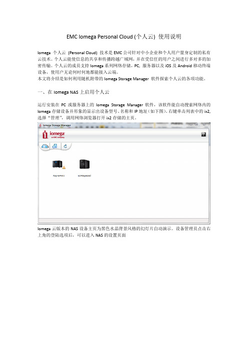
一、在Iomega NAS上启用个人云运行安装在PC或服务器上的Iomega Storage Manager软件,该软件能自动搜索网络内的Iomega存储设备并形象的显示出设备型号、名称和IP地址(如下图)。
右键单击列表中的ix2,选择“管理”,调用网络浏览器打开ix2存储的主页。
Iomega云版本的NAS设备主页为黑色水晶背景风格的幻灯片自动演示。
设备管理员点击右上角的登陆选项后,可以进入NAS的设置页面选择“云服务”中的“个人云”选项页面中的图示简单的介绍了个人云的工作原理。
在配置选项中,用户可以设置两种个人云模式:我的个人云—创建一个由该设备发起的个人云,作为主控邀请其他的成员(Iomega存储、PC、服务器)组成一个私有云其他个人云—作为成员之一加入一个由其它Iomega NAS设备创建的云用户只能选择其中一种模式使用。
比如,如果选择加入其他人的个人云,就不能创建属于自己的云。
在选择“我的个人云”后,系统会进入个人云初始化向导填入个人云的名称和管理员电子邮箱。
如果云的名称或邮箱已经被注册过,则系统会提示用户重新输入。
所有信息确认后,系统页面会显示个人云创建成功。
下图中的图示显示从ix2到路由器再到广域网的连接顺利,如果哪个环节出现问题,图标会从绿色的勾变成红色的叉,方便进行故障排查。
点开旁边的“设置选项”,可以看见云的信息。
- 1、下载文档前请自行甄别文档内容的完整性,平台不提供额外的编辑、内容补充、找答案等附加服务。
- 2、"仅部分预览"的文档,不可在线预览部分如存在完整性等问题,可反馈申请退款(可完整预览的文档不适用该条件!)。
- 3、如文档侵犯您的权益,请联系客服反馈,我们会尽快为您处理(人工客服工作时间:9:00-18:30)。
• 目标用户:
– 企业/机构的部门或办公室用户,小型企业办公室,家庭办公室以及已联网的数字 家庭用户
• 价值主张:
– 用EMC公司全球领先的专业数据存储保护技术,来帮助提高商务办公用户以及家 庭用户的数据安全保护及应用体验
1K
Iomega Confidential
产 品 价 格
10K
CX3-10 & NS20 AX4-5
全新
EMC Iomega StorCenter
产品性能(IOPS)
5
StorCenter™ ix2 硬件特性
• • • • • • 基于高性能低功耗的嵌入式平台 支持2块SATA Rev.3.5 高速硬盘 (3.0 Gb/s) 10/100/1000 Mb/s 自适应以太网端口 3个USB 2.0端口外接设备,以扩展容量或功能 非常小的物理尺寸,仅仅一个书本大 仅有一个散热风扇,非常安静
• 利用设备捆绑的、屡获殊荣的数据备份 及灾难恢复软件系统 EMC® Retrospect® Express ,每天定时、 自动备份保护您的电脑数据
• 借助于RSA公司久经考验的数据加密技 术,可以防止在您安装或者升级系统的 时候遭到黑客的攻击。RSA公司也是 EMC 公司旗下的数据安全专业公司 • 为防范磁盘驱动器故障可能导致的数据 丢失风险,系统内置了安全可靠的 RAID 1 (镜像) 数据保护技术,也支 持 JBOD 特性 • 系统故障预警电邮通知功能,会及时向 您通报备份任务失败的情况或者其他系 统问题 , 让您不用每天担心系统出了故 障而不知道
• 用于保护您个人电脑中的文档资料 • 周期性地定时为您的文档资料创建一个备份副本,并将其保存到别的硬盘驱动器上 • 这个解决方案非常简单、快速而且特别可靠 • 安装配置轻而易举 • 这个软件就随机捆绑在您购买的 StorCenter™ ix2 设备中,无需另外购买!
Iomega Confidential
• 支持Windows XP/Vista, MacOS以及Linux客户操作系统
• 高达4TB的硬盘容量,满足日益增长的数据存储需求
Iomega Confidential
16
Iomega® StorCenter™ ix2 主要益处 – 对小企业而言
增强的数据安全性 •利用系统内建的、屡获殊荣的数据备份及灾难恢复软件系统 EMC® Retrospect® Express ,每天定时、自动 备份保护您的电脑数据 •利用内置安全可靠的RAID (1) & JBOD 特性来防范磁盘驱动器故障可能导致的数据丢失风险 •系统故障预警电邮通知功能,会及时向您通报备份任务失败的情况或者其他系统问题 , 让您不用每天担心系统出 了故障而不知道 •借助于RSA公司久经考验的数据加密技术来保护系统安装和升级 •即插即用,设置向导会自动侦测设备并为您设置网络配置 •为需要进行个性化配置的高级用户也提供了相应的工具 •简单而直观的用户操作界面使得这个产品对任何人而言都是简单易用的 •任何联网的电脑系统都可以作为配置和管理的集中平台 •选择您使用的语言! 这个简单易用的界面已经针对11种语言做了本地化翻译 (包括英语, 西班牙语, 葡萄牙语, 法 语, 意大利语, 日语, 韩语, 简体和繁体中文, 德语、俄语) •网络打印服务器功能 允许您方便地与人共享三台打印机 •内置的多媒体服务器瞬间将您的数据存储设备转变成为多媒体网络共享中心 •只简单地将您的多媒体数据文件存放到您的 StorCenter ix2系统中, 然后就可以从您局域网中的任意一台兼容设 备,来播放、查看或者访问您的文件、照片、视频或者音乐 •在分别运行Windows®, Macintosh®, 或者 Linux® 等多种不兼容操作系统的个人电脑之间进行数据共享 •StorCenter ix2 是支持DLNA® 协议的, 意味着它能够与您从不同的生产厂商那里买来的,或者您原来旧有的数 字设备一起紧密配合使用. 能够与多种类型的设备互联和进行内容共享,这包括 DMAs (数字媒体适配器), UPnP™ AV(例如:游戏控制终端, 立体声网络收音机), iTunes™, PTP (例如. 数码相机) •高性能的 1GHz 系统中央处理器(CPU), 256MB 内存,SATA II 硬盘驱动器 (2) 以及 千兆以太网络连接 •蓝牙® 通信: 能简单快捷地将您的个人通讯录、照片图片或者其他信息,从您的蓝牙手机、个人数字终端PPC® 或者黑莓® 直接传送到您的个人电脑中去!需要配置可选的USB蓝牙适配器. •监控摄像机: 需要监视办公室里的情况吗?您只要简单地通过网络连接一个 Axis® 监控摄像机到您的 StorCenter ix2 系统,就能看到您所关心的情况了 •用户及群组设定: 在系统向导程序的指导下轻易地创建您的用户/群组帐号和管理共享文件夹的访问权限。也支持 17 对 Microsoft® Active Directory 服务的整合.
Iom配置可选的USB蓝牙适配器.
12
StorCenter™ ix2 具备如下特点
提供优秀的数据安全性 简单易用 丰富的功能与配置
Iomega Confidential
13
提供优秀的数据安全性
• RAID技术防止硬件故障造成数据丢失
• 屡获大奖的Retrospsect Express专业级备份软件
Iomega Confidential 11
StorCenter™ ix2 优秀而实用的系统特性
实用的、先进的系统特性是为了满 足各种独特的需求
•蓝牙® 通信: 能简单快捷地将您的个人通讯 录、照片图片或者其他信息,从您的蓝牙手 机、个人数字终端PPC®或者黑莓® 直接传送 到您的个人电脑中去!* •监控摄像机: 您需要监察在离开期间都发生 过什么事情吗? 只要通过以太网连接一个 Axis® 公司出品的监控摄像机到您的 StorCenter™ ix2 系统,它就能记录下您所 关心的情况. 保存下来的视频流信息可以在 将来进行回放察看或者用于处理和归档保存 •用户及群组设定: 在系统向导程序的指导下 轻易地创建您的用户/群组帐号和管理共享文 件夹的访问权限。也支持对 Microsoft® Active Directory 服务的整合.
安全锁 重置按钮 USB 2.0 接口
状态指示灯 电源按钮 QuikTransfer 按钮
USB 2.0 接口
千兆以太网 电源接口
驱动器仓
Iomega Confidential 6
StorCenter™ ix2 增强对用户数据的保护功能
StorCenter ix2 设备提供了多级 别的数据保护功能
• RSA BSAFE加密技术
• 基于用户权限的数据读写保护
• 内置部件状态监控系统和电子邮件故障通知功能
• 支持UPS以保护数据不受电源故障影响
Iomega Confidential
14
简单易用
• 易于管理 – 基于Web的管理界面,提供丰富的帮助 – 界面语言自动适应
– 支持与Active Directory集成,简化帐户管理
8
StorCenter™ ix2 安装和使用都非常简易
StorCenter™ ix2 确实非常简单!
• 设置向导会自动侦测到设备系统并设置您 的网络配置
• 当然我们也为那些高级用户提供了相应的工 具,以便他们可以根据自己的需要进行个性化 设置
• 设置和管理 都可以从同一个集中化的用户 端软件界面来进行,从同一个局域网内的 任何一台PC电脑都能进行操作 • 直观的用户操作界面, 利用容易识别和理解 的小图标, 让全世界的人都能同样简单轻易 地操作使用这个系统
StorCenter™ ix2 广泛的文档共享能力
这是一个简单易用的设备,却能够 同时提供文档的存放、组织以及 共享等多项功能
• 内置的多媒体服务器 能立即将您的 数据存储设备转变成为多媒体网络 共享中心 • 只需简单地将您的多媒体数据文件 存放到您的 StorCenter™ ix2系统 中, 然后就可以从您局域网中的任意 一台兼容设备,来播放、查看或者 访问您的文件、照片、视频或者音 乐 • 能同时为运行Windows®, Macintosh®, 或者 Linux® 等数 种不兼容操作系统的个人电脑之间 提供数据共享访问
– 分别针对商用和家用而设计的应用功能以及方便友好的用户访问界面,使得
StorCenter™ ix2更加简单易用和实现即装即用
Iomega Confidential 3
StorCenter™ ix2 目标用户环境
备份以保护数 据
共享打印 机 Microsoft Exchange 保存照片 Phone
• 基于浏览器的用户操作界面已经内置了11 种语言*的版本,不同民族的用户只需要简 单地选择界面语言即可
• 网络打印服务器功能 允许您方便地与人共 享两台打印机
Iomega Confidential
*英语, 西班牙语, 葡萄牙语, 法语, 意大利语, 日语, 韩语, 繁体和简体中文, 德语, 俄语
9
EMC Iomega StorCenter™ ix2-200d 网络存储设备
2011年6月
内容
• StorCenter™ ix2概述 • 硬件特性 • 软件特性 • 为什么选择StorCenter™ ix2 • 一些应用场景 • Q&A
Iomega Confidential
2
概述
• 产品定位:
– 旨在为小型企业、已联网的办公室和数字家庭用户,提供一套安全易用的、基于
Iomega Confidential 7
关于EMC® Retrospect® 备份软件 帮助备份您所有的数据文档!
EMC® Retrospect® 这个获过大奖的专业备份软件可以让您自己动手来 保护您有价值的信息资料。您只需要设置它定时自动、周期性地将您的电 脑数据备份到内置或者外接的存储设备上即可。