QJ178A随钻震击器使用说明书
随钻震击器使用说明书
文字说明1 概述2 结构与工作原理3 使用与操作4 维修5 地面实验附图图一 BZ随钻震击器外形图及主要尺寸图二运行位置示意图图三新装间隔衬套修理尺寸图四调节震击力方向示意图产品总图随钻震击器使用说明书1.概述机械式随钻震击器是全机械式随钻震击、解卡工具。
它集上、下震击作用于一体,可接触钻进作业中遇阻、遇卡等钻井事故。
它在不需要震击时,是钻柱的一部分,需震击时,随时可作业,因而提高了工作效率。
2.结构与工作原理。
结构外形及主要尺寸如图一。
内部结构如本说明书后附产品总图(图中未画出曲屈接头)。
本震击器是同类产品中结构最新式、最简化、操作最方便的。
上击工作原理图一所示为装配调试合格的位置,即准备出发(解锁)状态。
图二为局部放大图。
上图为准备击发位置。
运行轴与运行套的内齿对应啮合,运行套外部齿与摩擦衬套内部齿是齿顶对齿顶的摩擦状态。
当钻柱上提,通过上接头1,上控制套3,中部套筒28,下控制套37,下调节套29,压缩弹簧管25,26,27使运行套21相对摩擦衬套下移。
当运行套的外齿齿顶与摩擦衬套的齿间相对应时,运行衬套在运行轴的作用下涨开,运行轴的齿从运行套内齿滑出,如图二中图。
此时钻柱储备的能量释放,向上震击。
下放钻柱,整个工具又恢复图二上部的状态,即准备击发状态。
重复上述操作,就可使钻具解卡。
下击工作原理在运行套的上部,还有一组三件与26,27,28完全相同的弹簧管。
当下压钻柱时,通过上接头1,上控制套3,上调节套18,压缩上面一组弹簧管。
运行套相对于摩擦衬套上行,钻柱储能。
当达到预定的吨位,运行套的齿顶与摩擦衬套的顶间相对应,运行衬套涨开,运行轴齿从运行套内的齿中滑出,产生下击,与上击方向相反如图二下图所示。
3.使用与操作下井前的准备震击器下井前应该经台架试验合格,见本说明书第5节。
下井前震击器处于准备击发位置。
钻具配置应使震击器处于钻柱系列中平衡点以上的张力部分,并承受最少5吨的张力。
BZ型震击器最好是在张力状态下工作,但也可在压力状态下工作,可把震击器接入张力压力平衡点以下,承受5吨的压力。
震击式标准振摆仪使用说明书
震击式标准振摆仪使用说明书一、震击式标准振摆仪概述:ZBSX-92A震击式标准振摆仪适用于公路、建筑、地质冶金科研等部门的试验室对物料进行筛分分析,每次开机5分钟,既方便又简单完成分级工作。
整套结构由电动机控制箱,摆动座、定时器、夹筛盘、套筛等部分组成。
具有体积小、重量轻、外泽美观优雅,其结构先进,性能良好,转幅度大,振击力强,筛分效果好,使用装夹方便灵活。
好仪器,好资料,尽在沧州建仪()。
欢迎查询。
打造中国建仪销售第一品牌,树立沧州产品全新形象二、震击式标准振摆仪主要结构性能:主要由摆动机构,震击机构,夹紧机构等部分组成。
电动机通过转动轴,蜗轮付带摆动架上的主偏心轴旋转,从而又连带动其它两个付偏心轴回转促使整个筛组的摆动半径供应商,也等于偏心距的平面圆周摆动。
同时在同一台电动机带动另一对蜗轮付通过凸轮,顶杆装有筛组的摆动架,周期地顶起靠自重下落在机座的砧座上,使摆动架得到平面圆周摆动的同时进行震击。
三、震击式标准振摆仪主要特点:具有体积小,重量轻外型美观,装备自动停止装置,结构先进,性能良好,转幅度大,振击力强筛选效果好,能耗低,运行高效,耐磨性高,使用装夹套筛方便灵活等优点。
四、震击式标准振摆仪技术参数:1、筛子直径:300mm/200mm2、震幅;8mm3、振击次数:147次/分4、筛摇动次数:221次/分5、回转半径:12.5mm6、电机功率:0.75KW7、电压380V五、震击式标准振摆仪校准规程l、外观检查:1.1开启振筛机,检查各电器元件和机械零部件是否安全可靠。
2、振幅检测:2.1在振筛机停止状态下,用直板尺0mm刻度,对齐托盘上边缘,用手盘动传动装置,在托盘到最高点时,读取直板尺刻度,即为振幅,标准振幅为8mm,允许偏差为±lmm。
3、筛摇动次数的检测:3.1开启振筛机,用秒表计时,数5秒时间内筛子摇动次数,连续测3次,并计算出其平均摇动次数。
3.2筛摇动次数的标准值为221次/分,允许偏差±2次/分。
QJ-A型随钻震击器操作规程

QJ-A型随钻震击器操作规程1、概述QJ-A 型是一种全液压式随钻震击器,适用于各种钻井作业,使用时随钻具组合下井。
在正常钻井过程中因某种原因发生井下遇阻或卡钻时,可以通过提拉或下放钻柱,及时启动震击器产生向上或向下的震击力,来处理井下遇阻或卡钻,使钻井作业得以顺利进行,同时避免遇阻或卡钻进一步演化成为事故,造成更大的经济损失。
其主要特点如下:〈1〉上、下击一体,整机长度短,结构合理,安全可靠。
〈2〉上、下击释放力的大小可以在地面不解体的状态下分别进行调节,且调节操作非常简便易行,释放力大小的调节精确、稳定。
〈3〉属机械式震击器,产品性能受高温、腐蚀性介质等工作环境的影响小,能在较高井底温度和空气介质中工作,适用于包括欠平衡钻井在内的钻井作业。
2、结构原理QJ-A 型全机械式随钻震击器,主要由连接机构、密封机构、锁紧机构、弹性机构和打击机构组成。
结构示意见图(注:该示意图与实物不成比例)。
工作原理如下:当需要上击时,上提钻柱使震击器的心轴随之向上运动,弹性机构总成受力而产生弹性变形。
随着大钩拉力的不断增加,弹性机构总成的变形也随之增大。
当拉力达到锁紧机构上击标定释放力时,卡瓦突然完全张开,并嵌入卡瓦套内棱带中,锁紧装置打开,震击器进入了自由打击状态,卡瓦心轴失去卡瓦的约束,快速运动到固定行程的极限位置,打击机构即发生打击,从而产生强大的上击力。
然后,需下放钻柱使震击器复位,以备下次震击或继续钻进。
同理,当需要下击时,适当下放钻柱,直到施加到震击器上的压力达到锁紧机构的下击标定释放力。
此时,卡瓦突然完全张开,并嵌入卡瓦套内棱带中,锁紧装置打开,卡瓦心轴失去锁紧机构的约束,快速移动到固定行程的另一极限位置,打击机构即发生打击,从而产生强大的下击力。
然后,上提钻柱使震击器复位,以备下次震击或者继续钻进。
QJ-A 型随钻震击器可以通过调节上击调节螺母或下击调节螺母来改变释放力的大小。
调节上击调节螺母或下击调节螺母时,改变了卡瓦完全张开时弹性机构总成需要的压缩长度,从而改变了释放力的大小。
JZ型机械式随钻震击器

2、技术参数
型号 外径 内径 mm mm 接头螺纹 API 最大抗拉负荷 最大工作扭矩 MN k N·m 开泵面积 cm2 上击行程 mm 下击行程 mm 总长(锁紧位置) mm
JZ95 JZ121 JZ159Ⅲ JZ165 JZ178 JZ203
95
28
27/8REG NC38 NC46 NC50 NC50 65/8REG
jz型机械式随钻震击器机械表钻数男机械魔法背击苏州天钻机械神圣震击宏震击监视器和保险箱震击器钻展点击率裂震钢钻法术作用于一体,采用全机械式的随钻 震击器。其上、下震击负荷范围比较广,可以在维修站或现场 根据需要进行调节。特殊的挠性接头可以有效地降低震击器本 体的挠应力,因此它是打直井、深井、复杂井和定向井的首选 随钻震击工具。
0.8 1.4 2.2 2.2 2.3 2.5
8 13 15 15 15 20
32 60 100 100 100 176
200 198 149 149 147.5 144.5
200 205 166 166 167.5 176.5
5800 6 343 6 517 6 517 6 570 7 244
121 51.4 159 57 165 57 178 57 203 71.4
强震仪用户手册

第1章开始1.1 前言本用户手册包含关于GDQJ-II数字记录器的命令和信息。
第1章和第2章描述如何安装记录器和外部设备。
第3章描述仪器的配置和操作。
第4章叙述记录器的维护和服务。
第5章提供技术系统概述和总体操作的摘要描述。
第6章讨论高级安装程序。
阅读本手册时最好安装和运行GDQJ 4.0版监控软件。
1.2 介绍GDQJ-II是一台三通道数字记录器。
当配置一台三分量力平衡加速度计(传感器)时组成一套数字强震仪。
可选GPS时间系统和MODEM远程拨号系统。
GDQJ-II数字记录器包含三通道24bit模-数转换器。
采样率为50sps,100sps,200sps和400sps。
在采样率为200sps时提供大约120dB 动态范围。
降低采样率可以提高动态范围。
记录器具有8Mb(4M字)事件存储能力。
一般的讲,其工作原理是:传感器捡拾地面运动加速度信号,记录器连续地监视这些信号,看其是否满足地震事件检测临界(触发条件)。
当信号满足触发条件时,记录器在事件存储器上记录一个事件文件。
事件文件数据可以经过MODEM和公用电话网远程收取,也可以在现场通过直接电缆收取。
记录器也可以实时传送一个连续的数字数据流。
为了收取和处理数据,需要一个IBM兼容的PC机,运行Windows98,Windows 2000或Windows NT 4.0操作系统。
记录器安装在一个防水机箱内。
内部包括:·记录器电路板(三块)。
·浮充电蓄电池(12V,12Ah)。
·GPS时间系统OEM电路板。
仪器前面板有:·三分量力平衡加速度计(传感器)连接器。
·辅助口连接器,可提供高级特性。
·RS-232连接器,可接直接电缆或MODEM电缆。
·电源开关。
·外触发按钮开关。
·GPS使用开关。
·秒脉冲指示灯。
·记录指示灯。
仪器侧面前右卡簧下有GPS天线连接器。
使用液压随钻震击器
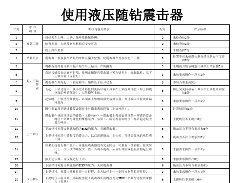
序号 1 2 3 准备工作 考 核 项 目 考核内容及要求 挡好天车大绳,大钩、吊环要拴保险绳; 检查井架,大绳及刹车机构应安全可靠 校正好指重表 配分 2 2 2 未检查扣2分 未检查扣2分 未检查扣2分 位置不对未使震击器在受拉状态下工作 扣5分 未用提升短节将震击器吊上钻台扣2分 未按要求操作一项扣1分 不符合要求扣5分 将任何夹持吊装工具卡在上轴拉开部位 扣5分 未按要求操作一项扣1分 评分标准
4
5 6 7 8 9
钻具组合
震击器一般接装在钻具的中和点偏上位置,使震击器在受拉状态下工作
将准备好的震击器用提升短节吊上钻台,严防撞击。
5
2 3 5 5 3
在连接螺纹处涂好密封脂,按规定扭矩将震击器拧紧在钻柱上,提起钻柱、取下 上轴卡箍(保管好)。
起、下钻 作 业 震击器在井内起、下钻过程中,始终处于拉开状态。 若起、下钻过程中,决不允许将任何夹持吊装工具卡在上轴拉开部位(即上轴镀 铬面的外露部分),以防损坏上轴。 起钻时,上轴呈拉开状态,必须在上轴镀铬面处装好卡箍,方可编入立柱放在钻 杆盒内。
上击解卡
13
上提钻柱时用中等程度的震击力,以后逐渐增加。上击时,指重表显示的吨位应 下降。 如果上提震击器不震击,可能是震击器没有完全回位,可重新下放钻柱,此次应 比上一次下放的吨位大一些。若再不震击,应分析原因或将震击器起出维 修。 按上述步骤,可反复进行上击。 下放钻柱对震击器施加约98KN的压力,关闭震击器。 上提钻柱,使震击器被拉开一定行程,在方钻杆上作一刻度来测量拉开行程。
10
11 12
操作前必须正确计算震击器作业时指重表的读数(上提吨位)。
震击器作业时指重表的读数(上提吨位)=震击器上部的钻具重量+所需的震击 吨位+钻具与井壁的摩擦阻力(估算),所需的震击吨位不允许超过最大 震击吨位。 下放钻柱对震击器施加约为98KN的压力,关闭震击器。
随钻震击器使用说明
目录文字说明1 概述2 结构与工作原理3 使用与操作4 维修5 地面实验附图图一BZ随钻震击器外形图及主要尺寸图二运行位置示意图图三新装间隔衬套修理尺寸图四调节震击力方向示意图产品总图随钻震击器使用说明书1.概述机械式随钻震击器是全机械式随钻震击、解卡工具。
它集上、下震击作用于一体,可接触钻进作业中遇阻、遇卡等钻井事故。
它在不需要震击时,是钻柱的一部分,需震击时,随时可作业,因而提高了工作效率。
2.结构与工作原理。
2.1 结构外形及主要尺寸如图一。
内部结构如本说明书后附产品总图(图中未画出曲屈接头)。
本震击器是同类产品中结构最新式、最简化、操作最方便的。
2.2 上击工作原理图一所示为装配调试合格的位置,即准备出发(解锁)状态。
图二为局部放大图。
上图为准备击发位置。
运行轴与运行套的内齿对应啮合,运行套外部齿与摩擦衬套内部齿是齿顶对齿顶的摩擦状态。
当钻柱上提,通过上接头1,上控制套3,中部套筒28,下控制套37,下调节套29,压缩弹簧管25,26,27使运行套21相对摩擦衬套下移。
当运行套的外齿齿顶与摩擦衬套的齿间相对应时,运行衬套在运行轴的作用下涨开,运行轴的齿从运行套内齿滑出,如图二中图。
此时钻柱储备的能量释放,向上震击。
下放钻柱,整个工具又恢复图二上部的状态,即准备击发状态。
重复上述操作,就可使钻具解卡。
2.3 下击工作原理在运行套的上部,还有一组三件与26,27,28完全相同的弹簧管。
当下压钻柱时,通过上接头1,上控制套3,上调节套18,压缩上面一组弹簧管。
运行套相对于摩擦衬套上行,钻柱储能。
当达到预定的吨位,运行套的齿顶与摩擦衬套的顶间相对应,运行衬套涨开,运行轴齿从运行套内的齿中滑出,产生下击,与上击方向相反如图二下图所示。
3.使用与操作3.1 下井前的准备3.1.1震击器下井前应该经台架试验合格,见本说明书第5节。
3.1.2下井前震击器处于准备击发位置。
3.1.3钻具配置应使震击器处于钻柱系列中平衡点以上的张力部分,并承受最少5吨的张力。
QY-A全液压随钻震击器使用说明书(英文)
QY-A DRILLING JAR OPERATION MANUALBEIJING PETROLEUM MACHINERY CO.SEP 2010ForewordThis new kind of drilling jar, including its structure, principle and application is introduced in this manual. After the drilling jar being used and repaired by customers, its reliability and performance may have some changes. These changes depend on the application conditions and maintenance level.Because of the continuous improvements on the products, some details in the manual may not be same as in actual operation. These differences don’t affect the understanding of the product's structure, the performance and the application by customers. If having any questions, please contact us.The service-life of the drilling jar and operation effects are related with not only designing and manufacturing but also properly operating of customers.We would like to supply customers with high quality products in compliance with specification of the quality assurance system of ISO9001, and also hope that the operators can carefully read the manual to insure the performance of products and successfully achieve the expectant drilling operations.The drilling jar and the information in this manual may not be suitable in some special applications. The operator should make right judgment on the selection and the application of the drilling jars.As the continuous improvements on the drilling technology, the customers will have new requirements on the application. We will be very happy to continuously improve our products to meet your special requirements.Welcome to contact us by the following methods!BPM Beijing Petroleum Machinery Co.Address: No. 41 Zhixin Road, Haidian District, Beijing 100083, China86-10-62098867Fax: 86-10-62311837,Phone: 86-10-83597657(Sale)86-10-83597659(Technical)Homepage: E-mail: bpm.tech@Content (1)1. Description2. Model Illustration (1)3. Principle (1)4. Application Notice (3)in the BHA (3)4.2 Position4.3 Frictionthe drill string (4)of (4)4.4 Pump-openForce4.5 Jarring up (5)4.6 Jarring down (5)4.7 Methods of the adjusting of the release force (5) (6)5. Maintenance5.1 Preparation (6)5.2 Disassembling Procedure (7)Procedure (8)5.3 Assembling5.4 Repair & Coordinate the limiter (9)6. Test & Oil Filling (10)Filling (10)6.1 Oil6.2 Release force test (10)6.3 Sealing Test (11)7. Trouble & Solutions (11)8. Damageable Components (12)9. Notices for Ordering (12)1. DescriptionQY-A hydraulic drilling jar is a new kind of drilling jar which is suitable for a wide range of drilling operations. This drilling jar overcomes the defects of pure mechanical drilling jar or pure hydraulic drilling jar and combines with merits of them. Mechanical lock and hydraulic delay works together in the process of jarring up and jarring down.The QY-A drilling jar has following features:1) It can avoid unexpected strike effectively.2) No need any safety clamps or other special actions on the drilling or tripping.3) Free position in the BHA (in tension, neutral or compression).4) Mechanical lock unit is not affected by the torque.5) The release force of jarring up or down can be adjusted on the drilling platform. Its operation isvery simple, exact and stable.6) Hydraulic delay allows the driller to adjust the jarring up or down force.7) Enclosed oil chambers increase seals and components life.8) Suitable to work in high temperature situation.9) It is an ideal tool for controlled directional well and horizontal well.2. Model Illustration3. PrincipleThe structure of QY-A drilling jar is shown in Figure 1, which be made up of housings, mandrels, valve unit, spring unit and lock unit and so on.QY-A is a new kind of drilling jar which combines the mechanical with hydraulic structures. The hook lifts the drill strings to make the mandrel move up, the spring unit takes place elastic deformation at the pull or push. The more energy from the hook, the spring unit does the greater deformation. When the deformation reaches high-point, the trip sleeve opens immediately and engages with friction sleeve, and then the jar enters the hydraulic-delay state. The cable hoist is baked at the same time. The drilling jar isCode (Drilling jar with adjustable release force)pulled slowly in the effect of pull force and hydraulic resistance force. The jar enters striking state after these series actions. The trip mandrel moves to the limit position quickly along its fixed path. After striking, set down the drill strings to make the jar reset for drilling or striking.Figure 1 the Structure of QY-A Drilling Jar Friction SleeveSpline MandrelStabilizerSpline Housing Upper Valve Housing Hydraulic Cylinder Lower Valve HousinSealBack NutSafe RingUpperValveMandrelValve UnitLower Valve MandrelUpper control HousingMiddle Control HousinConnect UnitLower HousingBottomTripLimiterLock ScrewUpper Adjusting SleeveSpring UnitPistonOil PlugLower Adjusting SleeveExtendedTrip SleeveLocated SleeveAdjusting SleeveWhen jarring down is needed, push the drilling jar until the pressure exceeds the release force. The lock unit opens soon and the trip sleeve opens immediately and engages with friction sleeve, and then the jar enters the hydraulic-delay state. The cable hoist is baked at the same time. The drilling jar is pulled slowly in the effect of pull force and hydraulic resistance force. The jar enters striking state after these seriesactions. The trip mandrel moves to limit position quickly along its fixed path producing huge jarring down force. The lock unit locked again when the drilling string is pulled, then the drilling or striking can be continued.The release force on the drill strings can be adjusted by the adjusting sleeve and the connect unit. In the adjustment process, first disassemble the cover screw, and then turn the adjusting sleeve by the spanner or the screwdriver alongside the thread to make an axial displacement and thus adjust the release force.4. Application Notice4.1 Prepare before down-hole operationThe drilling jar in the down-hole operation must be new or repaired after being used. The continuous working period of a new drilling jar for a single trip may not exceed more than 500 hours, not more than 300 hours for a repaired one. In high temperature or under the condition of acrid medium in the well fluid, it is not suitable to work for a long time. To avoid failure, the drilling jar should be repaired after being used in down hole, or else it is forbidden to use again.4.2 Position in the BHAJarring up or down of the hydraulic drilling jar is a whole section, and this can be subjected to a slightly pull force or push. In order to avoid free vibration of drill string affecting the jar’s life, it is important to avoid putting the jar on a neutral point of drill string. An ideal position is below the neutral point of the drill string, and this can make the pressing force on the drill string equal to the pump-open force.The drilling jar must be placed at the right position in the BHA to guarantee its proper effects and avoid some accidents. The jar's proper position is determined to the well conditions. Generally, the lower position, the better effect. In addition, the large pull or push force could result in unexpected strike.(1) Disposal on the lower location of the assembly (be pushed).The drilling jar is located above one drill collar at least where the collar is above the top centralizer.The drill collars located between a centralizer and a drilling jar can make the jar safer. For example, the drilling jar can not be stuck and dislodged by the rock cutting deposit. If a shock absorber locates in the drill strings, the drilling jar should be above it.(2) Disposal on the upper location of the assembly (be pulled).If it is predicated that the drill collars occur drill pipe stuck caused by pressure difference, the jar should be assembled on the position which is high enough in the drilling strings and always above the stuck point. But the disadvantage is that the distance between the jar and the stuck point would be too long and it could affect the jarring effect if the bit or the centralizers are stuck.4.3 Friction of the drill stringFriction is a kind of force generated between the drilling tool and borehole wall. Its empirical value is 50 kN ~200 kN. The friction is relevant with the BHA, mud condition and well bore structure. The force should be determined by the work site.During practical operation, the operators should exactly estimate the friction of the drill string.4.4 Pump-open ForcePump-open force is a kind of force exerting on the jar caused by the mud pressure in the drill strings in normal running. If the mud pressure is high enough, it will pull the jar open. Thus, the hook weight should deduce the pump-open force in the jarring up or down when calculates the force.The pump-open force is proportional to the pressure in the drill string and the piston equivalent area. So the pump-open force can be work out following:Pump-open force (kN) = piston area (mm2) -pumping pressure (MPa) ×10-3The piston equivalent area is related to the structure of the drilling jar. The pump-open force of QY-A drilling jar lists on the below table 1.Table 1 the Pump-open Force of QY-A Drilling Jar (kN)QY203AQY229AModel QY121A QY159A QY165A QY178APiston Area/mm24806 7835 7835 10722 13823 18850Pump Pressure/MPa971327555557 341381881077810 487819415026411014 6711027637721420 961571574.5 Jarring upWhen the jarring up is needed, lifting the drill strings to make the pull force reach the standardrelease force of the jar, an up-strike force would be produced. Pushing the drilling tools to make the jarreturn the reset position, the locking unit relocks again. Repeating the above steps will achieve the effectof continuous up strike. In jarring up, the hook load is calculated as follows:Hook load = hang weight on the drill string above the jar + frictional force on the drill strings +standard release force - pump-open force4.6 Jarring downWhen the jarring down is needed, lowering down the string to make the press force reach thestandard release force of the jar, a down-strike force would be produced. Pulling the drilling tools tomake the jar return the reset position, the locking unit relocks again. Repeating the above steps willachieve the effect of continuous down strike. In down strike, the hook load is calculated as follows: Hook load = hang weight on the drill string above the jar - standard release force- Frictional forceon the drill strings - pump-open force4.7 Methods of the adjusting of the release forceWe can make use of the adjusting sleeve on cover screw of the drilling jar by the spanner or thescrewdriver to adjust the release force. The upper adjusting sleeve is used for adjusting the up-strikerelease force, and the lower adjusting sleeve for the down-strike release force.There are 25 adjusting grooves on the circumference of the nut that is made letters on the bottomof the grooves. It marks "+" and "-" beside the cover hole, which represents the increase or the decreasedirection of the release force. Letters near the cover hole represent the position of the standard releaseTable 2 the adjusting value every grooveforce on ex-works or on the maintenance.During the adjusting (increasing or decreasing), when the upper or the lower adjusting sleeve can’t be adjusted, it reaches limited position, i.e. maximum or minimum release force.Notice: During the adjusting (increasing or decreasing), lock screw is forbidden to be disassembled or loosen.The every groove can adjust the release force as table 2. On the actual application, adjust the upper or the lower adjusting sleeve every time for one or a number of limiting grooves and record theletter till it reaches the proper tons. It canachieve the adjustment of the force5. MaintenanceOnce the new drilling jar continuously works in the down hole more than 500 hours or 300 hours for the repaired one, it must be checked and disassembled. It is suggested that the drilling jar should be abandoned after it has worked for 1500 hours or 2 years.Before disassembly, the drilling jar should be tested and the data should be recorded.5.1 Preparation①Break-out / Make-up equipment and proper tools, including pipe wrench, chain wrench, nylon slinging belt, etc. is needed.②Sealing and wearing parts. Model Adjusting Value (kN) QY121A 25QY159A 30 QY165A 30 QY178A 40 QY203A 50QY229A 60╋ ╋Page 7 of 12③Lubricants, molybdenum disulfide(MoS 2) lubricant oil and L-HM 32 hydraulic oil. ④Technical files and service drawings of the drilling jar. 5.2 Disassembling ProcedureIn disassembly, it is forbidden to damage sealing surfaces or outer surface of the thin wall housing. Before the disassembly, the drilling jar must be in reset position.The housing threads of the drilling jar are cone screw threads and painted Y680 bounded agent. Locally heat the connection place of all cone screw thread to make bounded agent invalid for dismantling. The surface temperature after heating cannot go beyond 250 and it is noticed that the ℃heating area cannot extend to protect seal parts from damage.(1) Before the disassembly, confirm the drilling jar in the reset (latched) position. Then prepare the oilcontainer, disassemble the oil plug by a spanner, empty the hydraulic oil in the cavity and disassemble the cover screws and lock screws. (2) Disassemble the bottom sub.(3) Disassemble the piston with the special tool and valve unit.(4) Disassemble the lower housing. After loosen the threads, hoist and dislodge it horizontally by thehanging belt. Take notice of the coaxial with upper control housing and the rest.(5) Disassemble the connect unit, turn out the lower adjusting sleeve. (Record the position of thembefore turning out.)(6) Disassemble the middle control housing. The disassembly way is same as the lower housing. Takeout the spring unit, separating sleeve, lining, friction sleeve and adjusting ring in the middle housing in sequence.(7) Disassemble the trip sleeve. First disassemble the extended mandrel, seize up the bottom end ofthe trip sleeve by the hanging belt and pulling it out by assembling test unit. Take out the separating sleeve and the spring unit on the mandrel in sequence.(8) Disassemble the upper control housing. The way is the same as the lower control housing. And turnout the lower adjusting sleeve. (Record the position of them before turning out.) (9) Disassemble the lower valve housing.(10) Disassemble the lower valve mandrel and the valve unit.(11) Disassemble the upper valve housing, as the way of the lower valve housing.(12) Disassemble the upper valve mandrel, the valve unit and the back nut.(13) Disassemble the spline housing, stabilizer and the spline mandrel.(14) Disassemble all the seal components.(15) Flush all the components by cleaning equipment. Check the injury status of the components. Afterchecking, the housings, the spline mandrel, the trip mandrel, friction sleeve, trip sleeve, spring unit, adjusting sleeve and the trip mandrel coupling should be detected. The displacements are replaced according to the destructive status.(16) After taking out the drilling jar from the well, all the seal components should be replaced every time.5.3 Assembling Procedure(1) Pick out invalid parts, substitute new available components and prepare a set of seal and the toolsfor oil injection.(2) Clip the stabilizer with the chain clamp of the assembling unit. First, assemble the wiper ring, sealring and supporting ring into the stabilizer. Then hoist the spline mandrel horizontally, and carefully boot the spline into it and pay attention not to damage the spline body and seal parts.(3) Insert the spline mandrel into the stabilizer(the bare length of the spline mandrel is about 310mm )(4) Assemble the orienting sleeve and seal components into the spline housing.(5) Assemble the clamp ring. Turn the back nut into the spline mandrel and install the spline mandreland the upper valve mandrel. Tighten the back nut and the upper valve mandrel.(6) Assemble the supporting ring to the upper valve mandrel; tighten it with the spline mandrel. Installthe seal part on the mandrel. Assemble the spline housing and upper valve housing together.(7) Pull the spline mandrel to the max trip and install the valve unit.(8) Assemble the seal parts and locker screw on the lower valve mandrel.(9) Assemble the hydraulic cylinder and upper valve housing.(10) Assemble the seal part on the lower valve housing, tighten the hydraulic cylinder and lower valvehousing together.(11) Assemble the seal part on the lower valve mandrel and tighten it with the upper valve mandrel andtrip mandrel (the special tool is needed).(12) Screw the upper adjusting sleeve into the upper control housing. When the distance between theend surface of the adjusting sleeve and that of the housing is “X” (the up strike is 0), the value of Page 8 of 12Page 9 of 12“X” is different from the model of QY-A drilling jar, check it on table 3, install the upper control housing.Table3 the distance between the end surface of adjusting sleeve and that of housingModelDistanceQY121A QY159A QY165A QY178A QY203A QY229AX 5 8.4 8.4 11.5 11.2 11.8 Y 4.7 8.4 8.4 11.8 11.6 12(13) Install the extended mandrel and the trip mandrel.(14) Assemble the spring unit and the separating sleeve on the mandrel in the order. Plug the trip sleeveinto the trip mandrel to make it into the groove, i.e. the reset position.(15) Assemble the bushing, adjusting ring, locating bush, and trip sleeve into the middle housing. Installthe middle housing.(16) Screw the lower adjusting sleeve into the connect unit and ensure that the distance between thehead face of the adjusting sleeve and that of the housing is Y (the down strike is 0), the value of “Y” is different from the model of QY-A drilling jar, check it on table 3, then install the connect unit. (17) Assemble the seal part on the piston and tighten it with the extend mandrel. (18) Assemble the lower control housing with the rest. (19) Install the top sub and assembling is accomplished.All the threads should be screwed down according to the make-up torque on table 4.Table 4 the make-up torque list of the threads (kN·m)ModelthreadsQY121A QY159/165A QY178A QY203A QY229A torque feed torquefeed torque feed torque feed torque feed housings 14 MoS 2 25 Y68035 Y68045 Y680 60 Y680mandrels 5 MoS 2 8 MoS 28 MoS 211 MoS 2 11 MoS 2Mandrel/piston 4 MoS 2 7MoS 28MoS 29MoS 211MoS 25.4 Repair & Coordinate the limiterIf the release force can not meet the requirement after long time using, repairing and coordinating the limiter is a good solution. If the custom wants to ascend the max release force, pare the end face nearing the adjusting sleeve. The length calculates as this formula:Page 10 of 12L=fptΔ25 L: The pared length, mm.p: The adjusting sleeve’ screw-pitch ,check it on table 5, mm.t: Difference between the max release force required on table 1and fact force, kN. Δf: Increase or decrease force dialing every groove of the upper/lower sleeve, kN.Table 5 the adjusting sleeve’ screw-pitch (mm)Model QY121A QY159A QY165A QY178A QY203A QY229Ap 4.5 4.5 4.5 4.23 4.5 6.356.Test & Oil Filling6.1 Oil FillingWhen the drilling jar has been assembled, it must be filled the oil into the cavity before the release force test.The liquid in the drilling jar is L-HM32 hydraulic oil. During oil filling, the drilling jar is required in the reset position.First, inject the barrel of the pump with the filtrated L-HM32 hydraulic oil. Before injection, lift upward the hole on the jar and then incline it by the traveling hoist at the angle of more than 30 degrees, in addition the large end of the mandrel is upward.The following is the connecting way between the oil pump and the hole on the jar. The hosepipe on the oil injection pump is connected with the bottom housing; one end of the return line connects to the hole on the spline body, and the other end inserts into the tubing. After connecting, the pump starts up. Wait till the air bubbles in the return line disappear for a long time so that all the remnant air is discharged, disassemble the pipe, assemble the pipe plug, and then put down the jar in horizontal position, disassemble the feed pipe, and finally install the pipe plug on the bottom housing, completing oil filling.6.2 Release force testThe reassembled drilling jars must come up to the standard in the release force test and seal test before used.After oiling the just-assembled drilling jar, test it’s jarring up and jarring down force on the push-pullBefore the test, it is suggested to locate the limiter as pre-disassembled. Please reference”6.4 repair & coordinate limiter” if you want to adjust the max release force in the adjustable extent of the limiter.After setting up the release force, record the letter locating near the setting nut vessel, and print it on the labeled vessel nearing adjustable aperture(print it behind all the letters ),then assemble limit nut and adjustable nut.The drilling jar must be reset after having been tested.6.3 Sealing TestThe nozzle is plugged by special pressure test connection. One end of the high-pressure hose is connected with the water inlet on the sub, the other end with the outlet on the electric pump. Make the air vent upward and disassemble the plug on the vent.Start up the pump and inject water into the jar. When the water fills up the jar and overflows from the air vent, stop the pump and install the core vent. After the above steps, start the pump again. When the pump pressure is up to 30MPa, stop it and retain the pressure for 5 minutes. If the pressure drops less than 0.5MPa, it represents the pressure test is ok. Disassemble the subs on the two ends. After drying the hole, paint the sealing grease and assemble the screw protector.7. Trouble & SolutionsBecause of the simple structure and the reliability of the mechanical QY-A drilling jar, a new jar or a jar after a normal repair won't have trouble. The trouble shooting during the application is as follows:a. the upper/lower adjusting sleeve can not be adjusted(1) If the upper/lower adjusting sleeve can adjust only toward one way, it indicates that the drilling jar has already been the max or min release force position. It is normal.(2) The drilling jar is not reset .Please pull or push it aptly. Push make jar reset when the jar has been up jarring or pull after down jarring.(3) The tool is too small to adjust the sleeve, please change a bigger one.b. No strike after the drill string lifted up(1) The jar is already at up-strike position. More drill springs would be lowered down to make the drilling jar be pushed, and then lift the strings up.(2) If the down-strike release force on the drilling jar is adjusted too low or too high, lift the jar outPage 11 of 12(3) If the lock unit of the jar is stuck and lodged, lift up the jar and repair it.c. No strike after the drill string lowered down(1) The jar is already at down-strike position, pull jar and lower down the drill string again.(2) If the down-strike release force on the drilling jar is adjusted too low or too high, lift the jar out to modulate.(3) After the drilling jar strikes for many times, and if the locking unit on the jar is stuck and lodged, lift the jar up and repair it.d. Vibration during normal drilling (unexpected strike)(1) If the release force on the drilling jar is adjusted too low, the vibration on the drill string will cause unexpected strike. Try to decrease the vibration on the string or increase the release force on the drilling jar.(2) If the jar in BHA locates at an inappropriate position, it will undertake so much larger pull force or compress force in normal drilling operation. If unexpected striking down, try to decrease the drilling pressure or increase the position of the drilling jar on the drilling assembly; otherwise, if unexpected striking up, try to increase the drilling pressure or decrease the position.8. Damageable ComponentsAfter the jar has worked in the well one time, all the sealing parts must be replaced.Check the stress-containing and frictional parts. If having any damage, replace it. Damageable components and special tools are shown in the following additional table.9. Notices for Ordering(1) Model of the products should be written clearly and completely.(2) If having special requirements on the connect threads, please give us a detailed information when ordering. If no details, we will supply our standard supplies.(3) Name, order number and quantity should be written clearly if ordering spare parts and tools.Page 12 of 12Additional Table 1:Damageable Components of QY121A Drilling JarSerial Number Items Order Number Quantity RemarkMandrel 9324610001 11 SplineSleeve 9314620004 22 SealHousing 9324610002 13 SplineNut 9314620008 14 Back5 Up Valve Mandrel 9324610004 16 Valve Unit 9314620200 2 complete setMandrel 9324610006 1Valve7 DownMandrel 9324610009 18 Trip9 Limiter 9314631007 2Screw 9314620010 210 LockScrew 9314620011 211 CoverUnit 9314620100 2 completeset12 SpringSleeve 9314630012 213 LocatedSleeve 9314630014 114 FrictionSleeve 9314630013 115 Trip16 TopSub 9324611010 117 Seal Components 9324610900 1 complete setSpecial Tools of QY159A Drilling JarSerial Number Items Order Number Remark1 Special Spanner 9316220810 Install valve mandrel piston2 Screw Plug 9316220820 Install trip sleeve3 Screw Block 9316220830 lead while trip installing4 Axle Pin 9316220840 Install valve coreIAdditional Table 1:Damageable Components of QY159A Drilling JarSerial Number Items Order Number Quantity RemarkMandrel 9326211001 11 SplineSleeve 9316220005 22 LeadHousing 9326210002 13 SplineNut 9316220009 14 Back5 Up Valve Mandrel 9326210004 16 Valve Unit 9316220200 2 complete setMandrel 9326210006 1Valve7 DownMandrel 9326210009 18 Trip9 Limiter 9316220014 2Screw 9316231002 210 LockScrew 9316230008 211 CoverUnit 9316220100 2 completeset12 SpringSleeve 9316220018 213 LocatedSleeve 9316220020 114 FrictionSleeve 9316220021 115 Trip16 TopSub 9326211011 117 Seal Components 9326210900 1 complete setSpecial Tools of QY159A Drilling JarSerial Number Items Order Number Remark1 Special Spanner 9316220810 Install valve mandrel piston2 Screw Plug 9316220820 Install trip sleeve3 Screw Block 9316220830 lead while trip installing4 Axle Pin 9316220840 Install valve corePage II of 12Additional Table 1:Damageable Components of QY159A Drilling JarSerial Number Items Order Number Quantity RemarkMandrel 9326211001 11 SplineSleeve 9316220005 22 LeadHousing 9326210002 13 SplineNut 9316220009 14 Back5 Up Valve Mandrel 9326210004 16 Valve Unit 9316220200 2 complete setMandrel 9326210006 1Valve7 DownMandrel 9326210009 18 Trip9 Limiter 9316220014 2Screw 9316231002 210 LockScrew 9316230008 211 CoverUnit 9316220100 2 completeset12 SpringSleeve 9316220018 213 LocatedSleeve 9316220020 114 FrictionSleeve 9316220021 115 Trip16 LowerHousing 9324610010 117 Seal Components 9324610900 1 complete setSpecial Tools of QY121A Drilling JarSerial Number Items Order Number Remark1 Special Spanner 9314620810 Install valve mandrel and piston2 Screw Plug 9314630810 Install trip sleeve3 Axle Pin 9316220840 Install valve coreIII。
- 1、下载文档前请自行甄别文档内容的完整性,平台不提供额外的编辑、内容补充、找答案等附加服务。
- 2、"仅部分预览"的文档,不可在线预览部分如存在完整性等问题,可反馈申请退款(可完整预览的文档不适用该条件!)。
- 3、如文档侵犯您的权益,请联系客服反馈,我们会尽快为您处理(人工客服工作时间:9:00-18:30)。
QJ178A随钻震击器使用说明书北京石油机械厂2002年10月目 录 1概述...........................................................................................................1 2型号说明.................................................................................................1 3技术参数.................................................................................................1 4工作原理.................................................................................................3 5随钻震击器在钻具组合中的配置...............................................4 6摩擦力和开泵力的计算方法.........................................................4 6.1钻柱摩擦力............................................................................................4 6.2开泵力......................................................................................................4 7操作方法.................................................................................................5 7.1向上震击.................................................................................................5 7.2向下震击.................................................................................................5 7.3释放力调节方法..................................................................................5 8维修...........................................................................................................5 8.1准备...........................................................................................................5 8.2拆卸步骤.................................................................................................6 8.3装配步骤.................................................................................................6 9试验与充油............................................................................................7 9.1释放力试验............................................................................................79.2充油...........................................................................................................8 9.3密封试验.................................................................................................8 10故障及排除............................................................................................8 11订货须知.................................................................................................9 1 概述 QJ178A型随钻震击器是一种新型可调全机械整体式随钻震击器,它具有两个特点:一是上、下击一体,整机长度短,结构简单,安全可靠;二是上、下击的释放力大小可以分别调节,且调节简便易行、准确、稳定。
2 型号说明 特征代号(A—释放力井场可调的随钻震击器)规格(外径178mm)产品代号(上下击一体的机械式随钻震击器)3 技术参数 QJ178A随钻震击器技术参数见表1。
表1 QJ178A随钻震击器技术参数型 号 QJ178A 外径尺寸 mm 178 水眼直径 mm 57 上击 kN 700 最大释放力 下击 kN 400 上击 kN 680~720 出厂标定释放力 下击 kN 380~420 最大抗拉载荷 kN 1800 最大工作扭矩 kN・m 15 长度 mm 5790 连接螺纹 API 4 1/2 IF 图1 QJ178A随钻震击器结构示意图4 工作原理 QJ178A随钻震击器结构示意图见图1,工作原理示意图见图2。
随钻震击器释放力的产生主要由卡瓦机构、弹性机构和打击机构来完成。
其中弹性机构用于储能,卡瓦机构在达到极限位置时突然张开,使卡瓦心轴突然释放,打击面产生打击,从而在钻柱中产生震击力。
调节机构可准确、稳定地调节释放力的大小。
(a) (b) (c)图2 工作原理示意图 QJ178A随钻震击器出厂和正常钻井时,处于复位状态,卡瓦的内棱带嵌入卡瓦心轴的沟槽内,此时卡瓦“抱紧”卡瓦心轴。
由于卡瓦心轴被其两端的弹性套限位不能移动,从而使卡瓦心轴不能轴向移动。
震击作业时,下压或上提钻柱,弹性机构受力变形,卡瓦与卡瓦套之间产生相对位移(图(b)),此过程为储能过程(钻柱被拉伸或压缩产生弹性变形)。
当钻柱对随钻震击器施加的拉力或压力达到标定释放力时,卡瓦外棱带进入卡瓦套内棱带的沟槽内,卡瓦突然张开,卡瓦心轴在钻柱拉力或压力的作用下从卡瓦中迅速拉出(图(c)),此时,被拉伸(或压缩)的钻柱突然收缩(或伸长),钻柱储存的能量瞬时释放,产生强大的震击力。
通过调节上、下调节螺母可以调节随钻震击器释放力的大小。
调节时仅需拆下固定螺钉和调整孔螺钉,用调节扳手拨动调节螺母,使调节螺母整体沿螺纹副转动,产生轴向位移,达到调节释放力的目的。
5 随钻震击器在钻具组合中的配置 该型震击器在钻柱组合中可以略受拉力或压力。
为避免自由震动影响使用寿命,应尽量避免放在中和点。
同时,所受的压力或拉力也不可过大,以免引起误击。
理想的位置是在钻柱中和点以下,随钻震击器受到的钻柱压力与开泵力相当的位置。
①配置在钻具组合的下部(受压)这时随钻震击器应装在顶部扶正器以上至少一根钻铤的位置。
扶正器和震击器之间的钻铤可增加随钻震击器的安全性,使岩屑沉积不致卡住随钻震击器。
如果钻柱中装有减震器,则震击器应位于减震器之上。
②配置在钻具组合的上部(受拉)。
如果预计钻铤将会发生压差粘附卡钻,则应将随钻震击器置于井下钻具组合中足够高的位置,使随钻震击器始终位于卡点之上。
其缺点是如果钻头和扶正器被卡,随钻震击器和卡点之间的距离太大会降低震击效果。
6 摩擦力和开泵力的计算方法 6.1 钻柱摩擦力 钻柱摩擦力是指钻柱和井壁之间的摩擦力,其经验数据是50~200kN,具体大小与钻柱组合、泥浆情况和井深结构等有关,由司钻根据现场实际情况确定。
6.2 开泵力 开泵力是指正常循环时,钻柱内泥浆压力对随钻震击器的作用力。
泥浆压力足够高时,开泵力将会使随钻震击器拉开,因此,计算上击悬重和下击悬重时都要减去开泵力。
开泵力的大小与钻柱内的压力和随钻震击器当量活塞面积成正比。
即:开泵力=泵压×当量面积当量面积的大小与产品的结构有关。
QJ178A随钻震击器的开泵力参见表2。
表2 开泵力(kN)泵压(MPa)型号3.5 7 10 14 17 20QJ178A 37.5 75 107 150 182 2147 操作方法 7.1 向上震击 上击作业时,上提钻柱使随钻震击器受到的拉力达到标定释放力,随钻震击器将产生向上震击。
然后下放钻具,使随钻震击器复位,卡瓦机构重新锁紧。
重复上述过程则可实现连续上击。
上击时大钩悬重可按下式计算:上击时大钩悬重=随钻震击器以上钻柱重量+钻柱摩擦力+上击标定释放力-开泵力7.2 向下震击 下击作业时,下放钻柱使随钻震击器受到的压力达到其标定的下击释放力,随钻震击器将产生向下震击。
然后上提钻具,使随钻震击器复位,卡瓦机构重新锁紧。
重复上述过程则可实现连续下击。
下击时大钩悬重可按下式计算:下击时大钩悬重=随钻震击器以上钻柱重量-下击标定释放力-钻柱摩擦力-开泵力7.3 释放力调节方法 卸下随钻震击器上的调整孔螺钉和固定螺钉,可以看到刻有深槽的调节螺母,用调节扳手或一字螺钉旋具(改锥)拨动调节螺母,可以调节释放力的大小。
上调节螺母用于调节下击释放力,下调节螺母用于调节上击释放力。
调节螺母圆周上有30个调节槽,槽底刻有字母,每调节一槽,释放力相应增(减)约20kN。
调整孔旁边标有“+”和“—”标记,分别表示释放力增加或减少的方向。
调整孔旁打印的字母表示出厂(或维修)时标定释放力的位置。
向增加释放力的方向调节,当达到最大释放力后,如果继续调节,释放力将会从最大变为最小,然后继续增加。