Integrating a hypertext interface into a syntax-directed programming environment
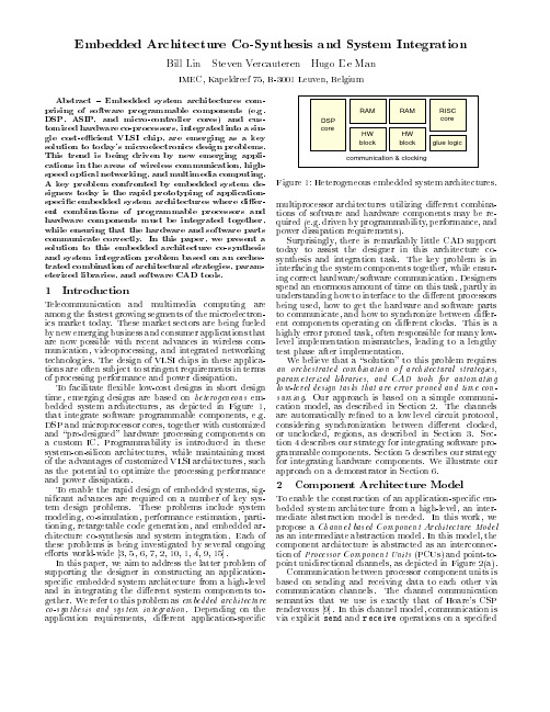
Embedded architecture co-synthesis and system integration
信息管理专业英语试题及答案

信息管理专业英语试题及答案一、写出以下单词的中文意思(每小题0.5分,共10分)1 algorithm 11 object-oriented2 optimization 12 subsystem3 transportation 13 analogous4 dissemination 14 authorization5 evaluate 15 collection6 reliability 16 database7 verification 17 distributing8 computerize 18 payment9 practical 19 warehouse10 manipulation 20 agility二、根据给出的中文意思,写出单词(每小题0.5分,共10分)1 n.组件,群件11 adj.分布式的2 n.反馈,反应12 n.构造,配置3 n.增殖,扩散13 vt.维持,维修4 n.扩散,传播14 vt.使标准化5 n.全球化,全球性15 n.识别,鉴定6 adj.多国的,跨国的16 adj.可接受的7 vt.分配,指派17 adj.兼容的8 adj.交互式的18 n.防火墙9 n.变化,转化,转换19 n.基本设施10 n.应用,应用程序20 vt.& vi.使同步三、根据给出的短语,写出中文意思(每小题1分,共10分)1 application program interface2 back up3 bar code4 base upon5 Business Intelligence6 c loud computing7 commercial service provider8 c ustomer churn9 customer relations management10 data independence四、根据给出的中文意思,写出短语(每小题1分,共10分)1 数据挖掘2 数据转换3 数据仓库4 脏数据,废数据5 外部存储设备6 遗传算法7 网格计算8 投资决策9 知识发现10 最小冗余五、写出以下缩略语的完整形式和中文意思(每小题1分,共10分)缩略语完整形式中文意思1 B2B2 B2C3 CRM4 DBMS5 ERP6 GIS7 HTTP8 IS9 SCM10 SQL六、把以下句子翻译为中文(每小题1.5分,共15分)1) Do you have any idea how to promote the sales of this product?2) Peter is confident of winning the post as the assistant to the managing director.3) There must be fair play whatever the competition is.4) She showed strong leadership during her first term in office.5) If you have any requirements, ask me.6) The managing director's only concern was how to improve the quality of their products.7) The cost of consumption articles is the first consideration, as far as most ordinary people are concerned.8) Appreciation of works of art is bound to be dominated by a particular kind of interest.9) We sought an answer to the question, but couldn't find one.10) The program was implemented with great efficiency and speed.七、把以下句子翻译为英文(每小题1.5分,共15分)1) 没有好的管理,生意是不可能做好的。
Hypermill教程
2009.1Trendsetting Technologies and Novel FunctionalityweiverpNew paradigm in manufacturinghyper MILL® 2009.1 off ers innovative functions and a new multi-dimensional, process-oriented CAM platform.This is a unique platform which, with comprehensive features for planning, organising and implementing machining processes, al-lows users to organise these processes with a view to the future. Users can aggregate manufacturing expertise and thus safely and fl exibly implement complex tasks and reduce production times.This is made possible through the following features:– A ssociative linking of geometries, tools and technology macros – A utomatic inclusion of modifi ed external data– D efi nition of processing standards using customized process features– A utomated programming associated with the above– A bility to defi ne individual diff erences between similar geomet-ries by simply editing/deleting individual constraints– P rocess-oriented workfl ow with signifi cant reduction in auxiliary processing timesHere, hyper MILL® 2009.1 is building on past experience. As a benefi t, users need not relearn how to program. Since users can continue to work in the same manner as previously, they can gra-dually learn this new comprehensive method of programming.Customized Process Fea-tures: CPF allows users to defi ne various characte-ristic geometry sequen-ces using freely defi nable machining processes.8page Transformations: Trans-formations allow users tomove and/or copy a program across spatial coordinates.9page Job linking: This featuremerges machining ope-rations using a commontool into a single machi-ning job.Production mode: This feature automatically optimises all transiti-on moves to minimize processing times for standard parts.Mirroring: This functionmirrors input data acrossa plane and calculates anindependent toolpath onthe basis of the mirrored geometry.11page 12page 10pageSystem requirements:Windows XP, Windows Vista.hyper CAD® 2008.1, thinkdesign2008.1 Software languages: D, E, I, F, ESP, J, NL, PL, CZ, RU, CHIN pageManagement functions and tools 5 General functions 9 Rotate 13 2D machining 15 3D machining 17 5AXIS machining 21 Contact 24 Contents34Analysis functions➜ P arts verifi cation for effi cient job planning and CAM programming The new modelling and surface analysis tools allow users to quickly and easily determine which element properties in a component are relevant for machining tasks. By simply clicking on a surface, users receive impor-tant information on the surface type (radius, plane, free-form surface), minimum and maximum radius, position and angle as well as picking point coordinates for the selected frame system. When selecting two elements, the minimum distance between the two surfaces is displayed. In addition to analysing individual surfaces, hyper MILL ® can automati-cally search for all planes and radii on a component and also mark their positions and sizes accordingly. Various machining data, such as machining type or tolerances, are often compiled into standardised colour tables. These can be stored in h yper MILL ® so that users have easy access to tolerance and fi t data for holes or other geometries to be machined in a component. Manual positioning of any tool allows users to quickly and easily check whether areas that are diffi cult to access can be machined and, if so, at which angle. To do this, any tool defi ned in hyper MILL ® can be moved toany position and freely rotated around all axes.Analysis of existing radii on componentModel analysisIntegration of standar-dised colour tablesMa n a g e m e n t f u n c t i o n s a n d t o o l s Compound job➜ F or well-structured job listsAssociative jobs permanently link all parameters with the original. Changes to the job template are automatically copied to the associated jobs. Any individually defi nable parameter for a job step can be disas-sociated from the template by a simple mouse click so that it can be defi ned diff erently for this job step.This new functionality allows users to work more fl exibly and quickly edit common machining strategies where only few parameters diff er across several steps in a job. All parameters that have been disassociated from the job template are displayed in a separate window of the job step where they can be edited.Associative job copies➜ F or associative copyingInput screen Clear structuring according56➜F ast and easy editingThe redesigned user interface allows additional options to edit seve-ral steps in a job. Next to central parameters such as surface, depth,allowance or infeed, various other geometry selections such as millingor milling surfaces and even macros can be changed globally acrossmultiple jobs.Extended setup➜I mproved management of data and fi les used in hyper MILL®This function simplifi es the handling, entry and confi guration of di-rectories containing essential hyper MILL® data such as postprocessorinformation, machine defi nitions and NC fi les. When saving a CAD model,a backup copy can be created automatically. The storage location andnumber of backup copies are freely defi nable.Editing screenSetup defi nitionIn addition to a holder, thicker shaft and head, tools can now also be defi ned with extensions. For optimum processing, the required length of a tool is calculated during the entire collision check. Here, the software calculates the required length. After the calculation, h yper MILL ® returns the length by which the defi ned tool should be extended or shortened in order to perform the step without colliding.➜ E xtended tool defi nition and collision checks7Ma n a g e m e n t f u n c t i o n s a n d t o o l sTool length calculationhyper MILL ® 2009.1 comes equipped with a fully redesigned high-perfor-mance tool database. Tools can now be defi ned with greater versatility and much more realistically. To fully assemble a tool, freely defi nable tool extensions are now available with corresponding coupling systems. By entering the technology data for tool extensions, copying tools into ajob list automatically changes the corresponding technology values.In addition to the material-specifi c cutting data, users can also createvarious profi les for each tool defi ned in the database. Thus, diff erent applications can be predefi ned and selected in the job steps – even for the same workpiece and cutting materials.➜ E xtensive defi nitions of tools using technology dataTool databaseFreely defi nable tool extensions …... Correspondingcoupling systems Freely defi nable tool holders8CPF – Customized Process Features (optional)➜ A utomation of CAM programming and defi nition of company-specifi c machining standardsExtended feature technology allows users to defi ne any type of complex machining sequence and store it as a technology macro so that it can be quickly and easily applied to various similar machining tasks. This is based on process-oriented links between characteristic geometries with freely defi nable sequences of various machining strategies – from 2D, 3D and 5AXIS milling to turning.The same elements can be used in various work steps for diff erent tasks. For instance, a surface selection can be used as a stop surface in one step and a milling surface in the next step.The various geometry elements can be selected manually in the model or selected automatically by defi ning selection rules. Thus similarly struc-tured external data can be used to quickly program similar components or for making design changes later on.Selection scriptOperating screen for Customized Process Features9Ge n e r a lf u n c t i o n s Using transformations, it is possible to reproduce programs for ma-chining identical or similar geometries within a component or several identical components that are clamped together. By freely transforming machining steps across spatial coordinates, users can simplify their pro-gramming workload and reduce costs. In other words, multiple copies of machining steps can be placed along the X and Y axes or rotated around a freely defi nable axis.With transformations, users can easily and conveniently create programs for multiple components clamped within a single plane or in a tombstone fi xture, for example. Since the “copies” are associated with the job temp-late, modifi cations to a program or geometry can be implemented quickly and easily. Any changes to the job template are copied automatically by hyper MILL ® to the associated jobs. Furthermore, each parameter can be modifi ed individually. Since users can make local changes or even delete parameters and dependencies, workfl ows remain highly fl exible (see also “Associative job copies”, page 5).Another powerful feature is that users can perform collision checksrelative to the fi nished part for programs that have been off set or rotated. This means that jobs involving tombstones or multiple setups can be programmed effi ciently and reliably.Transformations can be applied to all job steps.Transformations➜ F or reproducing machining jobs on identical orsimilar geometriesSpatial copies of programsCopies of program sections for components with identical elements10➜C reates symmetrical geometries or geometrical planes incomponents and determines entire machining programs formirrored componentsIn contrast to simple mirroring actions performed by machine controllers,h yper MILL® does not merely mirror the NC paths but also the entire step.This requires recalculating an independent toolpath for the mirrored geo-metry. Here, h yper MILL® automatically adapts the required technologiesso that climb milling movements remain intact. Automatic approach andretract strategies, curve orientations and optimised infeed movementsare taken into consideration in mirrored jobs.Mirroring automatically creates an associated element in a browser. Anychanges to the original are automatically applied to the mirrored versi-ons. Again, every parameter can also be modifi ed individually if required.Mirroring can be applied to all job steps as well as to the entire job list. Geometry and boundaries are mirrored11Ge n er a l f u n c t i o n s ➜ F or intelligent links between jobs and eff ective reduction of transition moves Multiple job steps to be machined with the same tool can be combined into a single step using job linking. Here, each of the job steps remains unchanged. h yper MILL ® calculates the NC toolpaths between these steps with respect to the workpiece and performs a collision check. Each job link is established independently of the type of machining (2D, 3D and 5AXIS machining) and machining direction. Even undercut areas can be approached safely with job linking. This new unique function allows users to combine multiple strategies into a single processing cycle. The benefi t is that there are no transition moves to safety planes between these jobs, saving much non-cutting time. And the job linking moves are collision controlled.With and without job linking Collision-checked link12Production mode➜ A utomatic optimisation of transition moves for shortestp ossible machining times of standard parts Production mode is a new function that lets you minimise all transition moves within a job. h yper MILL ® automatically optimises fast travel move-ments according to the path length by stepping over or sideways around the geometry to the starting point of the next path. Lateral movements prevent unnecessary plunging movements. By including the stock in the collision calculation, h yper MILL ® ensures that transition moves remain reliable.Extended collision checks➜ B etter process reliability, improved surface qualityThe safety allowances for tool collision checks can now be defi ned in even higher detail. Each of the various tool components (spindles, holders, extensions) can be defi ned with separate allowances for checks against the model. Next to collision checks, the required length can also be calculated. Depending on the entry, the tool is not only extended but the shortest possible tool is also calculated (see also “Tool definition”).Machining without production mode Machining with production modeDefi nition with safety allowanceR ot a t e Advanced stock defi nition➜ C onvenient and easy defi nition of turning stockh yper MILL ® provides users with various options for defi ning stock for turning processes: 1) The user chooses the stock contour as a 2D sketch.2) Relative to a rotational axis, the software automatically calculates a rotationally symmetrical stock that contains the entire CAD model. 3) The user generates the turning stock on the basis of 3D milling stock or STL model.Here, the new function for defi ning the bounding geometry makes the workfl ow very easy and user-friendly. The corresponding surfaces are simply selected by clicking them with the mouse. Next, users can enter a stock allowance applicable to all contours or defi ne separate allowances for each contour. h yper MILL ® automatically creates the correspondinggeometry. Furthermore, a parallel stock allowance can also be defi ned as an off set to the contour – as required for cast components, for instanceh yper MILL ® automatically suggests a minimum size for the stock. Based on these values, users can defi ne global or separate stock allowances or even defi ne the fi nal dimensions.13Slope-dependent turning➜ F or optimised cutting conditions during fi nishingThese new functions are specifically intended so that users can machine fl at and steep regions. To defi ne the areas to be machined, the user fi rstselects the entire contour. Next, the user defi nes the areas that are to be machined and the maximum slope angle to be used in the single-step process.Slope-dependentturning deactivatedSteep regions Flat regions Defi ning the b ounding geometry14Feature recognition for pockets ➜ D etection of breakthroughs Pocket feature recognition has been extended to include breakthroughs. In addition to closed pockets, pockets with islands and pockets with open sides, hyper MILL ® now also detects breakthroughs. In automatic mode, any closed breakthroughs within the model are detected in the frame direction. In manual mode, users can specify the start and endpoints to also detect open areas or separate breakthroughs.Open pockets without fl ooringPockets without a bottom surface Playback ➜ S imple creation of toolpaths Toolpaths can be generated manually by moving the tool across the mo-del with the mouse. Once defi ned, hyper MILL ® performs a collision check for the tool against the model. If a collision is detected, the software mo-difi es the tool paths to place them at collision free points on the model.Easy generation of NC toolpathsReliable programming of machi-ning processesWith collision checks2Dma c hining 152D contour milling➜ U nique potential for optimisation with reductions inp rogramming and machining timeshyper MILL ® 2009.1 provides new functions for optimised 2D machining of contours. The “Automatic orientation”, “Fast travel optimisation” and “Contour sorting” functions mainly assist users while programming mo-dels with multiple contour areas or for machining automatically detected pocket features.The automatic search feature for starting points can be used together with new intelligent approach and retract macros to ensure the transition moves are always performed in the most suitable areas for the technolo-gy in use. Other functions such as automatic step-down levels, multiple infeeds in the vertical and horizontal machining directions, and defi niti-on of additional fi nishing allowances allow users to make eff ective and reliable use of their tools. As an added benefi t, the surface quality also improves.The new production mode allows the created milling paths to be checked against the current stock material. Any traversing or other redundant mo-vements that are detected are reduced to a minimum. Using a collision check, fast travel movements can be performed directly within a model or in its vicinity. This eliminates the need for repeated, time-consuming positioning movements along the clearance plane. As a result, machiningtimes are reduced and the process becomes more reliable.Automatic cut divisionTrimming against the model Fillet outside edges…... with extended edgesComplex deep holes with various steps and cross-holes can be pro-grammed separately using hyper MILL ®. The infeeds, drilling speeds and coolant can be controlled separately for diff erent areas and geometry elements such as guide bushings, pilot holes or cross-holes. Here, the strategy automatically detects cross-holes in the specifi ed stock.Optimised peck drilling ➜ D rilling deep holes16Automatic detection of cross-holesInput screen for optimising processCross-hole/breakthrough Pilot holeF1, S1, M9F2, S2, M8F3, S3, M9F4, S4, M9F5, S5, M9F2, S2, M83D m a c hin i n g17Stock roughing➜ O ptimised and reliable stock roughing with high milling quality and precision To improve milling paths and prevent empty cuts and/or very short movements, “minimum material removal” can be defi ned to optimise NC toolpaths. Here, hyper MILL ® fi lters out small areas of material. Using the new parameter “Force contour cutting”, stock roughing can also be used for machining rest materials as well as for preliminary fi nishing. As early as during the roughing phase, an allowance is applied equally across the entire component. After entering the new tool parameter, “core diame-ter” and “core height”, hyper MILL ® provides the best possible plunge movement. Here, the infeed is calculated automatically and adapted to the e for preliminary finishing With minimum material removalWithout minimum material removalFor higher precision 3D radius compensation ➜P recise machining18A bullnose endmill can be used to detect rest material areas as well as for actual machining. A rest material area that has not been machined due to potential collisions can be used as a reference for a subsequent machi-ning step with modifi ed tools (e.g., longer tool lengths). This ensures that only the areas that could not be completed during the fi rst step are machined in this next one.With the new machining strategies for cavities, it is now possible to create grooves, ribs or deep, narrow grooves in a single machining step. Deep areas containing large amounts of material can be cleared comple-tely and eff ectively using a constant infeed.➜ F or effi cient machining and milling ribs and groovesAutomatic 3D rest materialPrevious job as reference3D m a c h i n i n g19Bullnose endmill as reference toolVisualisation of non-machined areaMilling grooves20Drill point optimisation➜M ore eff ective machining with minimised tool path lengthsDrill hole optimisation is now also available for 5AXIS drilling. In additionto the shortest paths between the drill holes, the preferred axis of rota-tion still has to be defi ned. This combines the drill holes so that depen-ding on the settings, fi rst the C-axis or the A/B-axis is moved. Furthermo-re, users also have the option of using the Z-height as a sorting criterion.Optimised drilling for B-axisOptimised drilling for Z-levelOptimised drilling for C-axis5A X I S m i l l i n gAutomatic 5x Rest Machining allows users to freely combine various approach strategies with each other. Depending on the given require-ments, users decide whether only to approach or to machine the various rest material areas using a vertically aligned tool. For areas that can be machined using a vertical or angled tool, the area not yet processed can also be milled simultaneously.➜ O ptimised machining and straightforward programming a ccording to your specifi c needsAutomatic 5AXIS rest materialWith automatic search feature for constant tilt angles21Automatic indexing➜ M ore possibilities for defi ning tool positions according to your specifi c needsThe 5AXIS machining strategies of profi le fi nishing, Z-level fi nishing and reworking now include automatic indexing functions. The tilt strategy automatically subdivides the component into separate areas that can be machined at a constant tilt angle.By defi ning boundaries and segment limits, areas can be defi ned wher-ein a specifi c tilt angle is to be used. Optionally, the entire machining procedure can be merely indexed or even defi ned with a vertical tool po-sition. The remaining areas to be machined either vertically or at a tilt can be optionally calculated as NC toolpaths for simultaneous machining.Areas with constant tilt angleContact© A l l r i g h t s r e s e r v e d , O P E N M I N D T e c h n o l o g i e s A G , W e s s l i n g , G e r m a n y . P u b l i s h e d a u g u s t 2009. A l l i n f o r m a t i o n s u b j e c t t o c h a n g e . N o r e p r o d u c t i o n a l l o w e d w i t h o u t t h e c o n s e n t o f t h e p u b l i s h e r .OPEN MIND Technologies AG is represented in Germany, Italy, France, Switzerland, UK, USA, Singapore, China, Japan, Taiwan and India and a member of the Mensch und Maschine techno-logy group, www.mum.de.OPEN MIND Technologies AGArgelsrieder Feld 5 • 82234 Wessling • Germany Phone: +49-81 53-93 35 00E-Mail: I nfo.Europe@Support.Europe@OPEN MIND Technologies UK Ltd.John Eccles House • Robert Robinson Avenue Oxford Science Park • Oxford OX4 4GP • UK Phone: +44-18 65-33 80 26E-Mail: @OPEN MIND Technologies USA, Inc.39111 W.Six Mile Road • Livonia MI 48152 • USA Phone: +1-888-516 1232E-Mail: Info.Americas@OPEN MIND Technologies Japan Inc.KS Building • 1-31-11, Kichijojihoncho Musashino-shi • Tokyo 180-0004 • Japan Phone: +81-4 22-23-53 05E-Mail: Info.Japan@OPEN MIND Technologies Asia Pacifi c Pte. Ltd.10 Ubi Crescent • #05-22 Ubi Techpark Singapore 408564 • Singapore Phone: +65-67 42-95 56E-Mail: @OPEN MIND Technologies China Co. Ltd.Suite 1507 • Le Kai Tower • 660 Shang Cheng Road Shanghai 200120 • China Phone: +86-21-5887 6572E-Mail: Info.China@OPEN MIND Technologies Taiwan Inc.3F, No. 153, Hwan-Pei Road • Chungli City 320 Taiwan, R.O.C.Phone: +886-3-4613125E-Mail: Info.Taiwan@OPEN MIND Technologies India 1109, 11th fl oor, Barton Center • #84, M.G. Road Bangalore 560001 • India Phone: +91-80-30504647E-Mail: Info.India@。
我的教育英语作文

Education is a fundamental aspect of human development and societal progress.It is not merely a process of acquiring knowledge but also a means of personal growth and social integration.In this essay,I will discuss the importance of education,the challenges faced in the educational system,and the role of education in shaping the future.The Importance of Education1.Personal Development:Education is crucial for the intellectual and emotional growth of an individual.It helps in developing critical thinking skills,problemsolving abilities, and creativity.It also fosters a sense of curiosity and a desire to learn,which are essential for personal development.2.Social Integration:Education plays a vital role in integrating individuals into society.It imparts values,norms,and social skills that are necessary for harmonious coexistence.It also helps in understanding and respecting cultural diversity,which is crucial in our increasingly globalized world.3.Economic Growth:A welleducated populace is a key driver of economic development. Education equips individuals with the skills needed for employment and entrepreneurship, contributing to a countrys economic prosperity.4.Civic Responsibility:Education instills a sense of civic responsibility and encourages active participation in democratic processes.It helps individuals understand their rights and responsibilities,fostering a more informed and engaged citizenry.Challenges in the Educational SystemDespite its importance,the educational system faces numerous challenges:1.Access to Education:Inequality in access to education is a significant issue, particularly in developing countries.Factors such as poverty,gender discrimination,and geographical isolation can limit educational opportunities for many.2.Quality of Education:Even where access is available,the quality of education can vary greatly.Overcrowded classrooms,outdated curricula,and a lack of qualified teachers are common problems that affect the educational experience.3.Technological Integration:With the rapid advancement of technology,integrating digital tools and resources into the educational process is becoming increasingly important.However,this presents challenges in terms of infrastructure,training,andensuring equitable access to technology.4.Lifelong Learning:The concept of lifelong learning is gaining prominence as the pace of change in the job market accelerates.The educational system must adapt to support continuous learning and skill development throughout an individuals life.The Role of Education in Shaping the FutureEducation is a cornerstone for building a better future.It is through education that we can:1.Promote Equality:By ensuring equal access to quality education,we can reduce social and economic disparities and promote a more equitable society.2.Encourage Innovation:Education fosters a culture of inquiry and experimentation, which is essential for driving innovation and addressing the complex challenges of the future.3.Prepare for the Future of Work:As the nature of work evolves,education must equip individuals with the skills needed for the jobs of tomorrow,including digital literacy, adaptability,and the ability to work in diverse and dynamic teams.4.Sustain Global Development:Education is a key factor in achieving the United Nations Sustainable Development Goals,contributing to poverty reduction,health improvement, and environmental sustainability.In conclusion,education is a powerful tool for personal and societal transformation.It is our collective responsibility to ensure that education is accessible,equitable,and of high quality,empowering individuals to contribute positively to the world around them.As we look to the future,the role of education in shaping a more just,prosperous,and sustainable world cannot be overstated.。
低频活动漂浮潜水船声探测系统(LFATS)说明书

LOW-FREQUENCY ACTIVE TOWED SONAR (LFATS)LFATS is a full-feature, long-range,low-frequency variable depth sonarDeveloped for active sonar operation against modern dieselelectric submarines, LFATS has demonstrated consistent detection performance in shallow and deep water. LFATS also provides a passive mode and includes a full set of passive tools and features.COMPACT SIZELFATS is a small, lightweight, air-transportable, ruggedized system designed specifically for easy installation on small vessels. CONFIGURABLELFATS can operate in a stand-alone configuration or be easily integrated into the ship’s combat system.TACTICAL BISTATIC AND MULTISTATIC CAPABILITYA robust infrastructure permits interoperability with the HELRAS helicopter dipping sonar and all key sonobuoys.HIGHLY MANEUVERABLEOwn-ship noise reduction processing algorithms, coupled with compact twin line receivers, enable short-scope towing for efficient maneuvering, fast deployment and unencumbered operation in shallow water.COMPACT WINCH AND HANDLING SYSTEMAn ultrastable structure assures safe, reliable operation in heavy seas and permits manual or console-controlled deployment, retrieval and depth-keeping. FULL 360° COVERAGEA dual parallel array configuration and advanced signal processing achieve instantaneous, unambiguous left/right target discrimination.SPACE-SAVING TRANSMITTERTOW-BODY CONFIGURATIONInnovative technology achievesomnidirectional, large aperture acousticperformance in a compact, sleek tow-body assembly.REVERBERATION SUPRESSIONThe unique transmitter design enablesforward, aft, port and starboarddirectional transmission. This capabilitydiverts energy concentration away fromshorelines and landmasses, minimizingreverb and optimizing target detection.SONAR PERFORMANCE PREDICTIONA key ingredient to mission planning,LFATS computes and displays systemdetection capability based on modeled ormeasured environmental data.Key Features>Wide-area search>Target detection, localization andclassification>T racking and attack>Embedded trainingSonar Processing>Active processing: State-of-the-art signal processing offers acomprehensive range of single- andmulti-pulse, FM and CW processingfor detection and tracking. Targetdetection, localization andclassification>P assive processing: LFATS featuresfull 100-to-2,000 Hz continuouswideband coverage. Broadband,DEMON and narrowband analyzers,torpedo alert and extendedtracking functions constitute asuite of passive tools to track andanalyze targets.>Playback mode: Playback isseamlessly integrated intopassive and active operation,enabling postanalysis of pre-recorded mission data and is a keycomponent to operator training.>Built-in test: Power-up, continuousbackground and operator-initiatedtest modes combine to boostsystem availability and accelerateoperational readiness.UNIQUE EXTENSION/RETRACTIONMECHANISM TRANSFORMS COMPACTTOW-BODY CONFIGURATION TO ALARGE-APERTURE MULTIDIRECTIONALTRANSMITTERDISPLAYS AND OPERATOR INTERFACES>State-of-the-art workstation-based operator machineinterface: Trackball, point-and-click control, pull-down menu function and parameter selection allows easy access to key information. >Displays: A strategic balance of multifunction displays,built on a modern OpenGL framework, offer flexible search, classification and geographic formats. Ground-stabilized, high-resolution color monitors capture details in the real-time processed sonar data. > B uilt-in operator aids: To simplify operation, LFATS provides recommended mode/parameter settings, automated range-of-day estimation and data history recall. >COTS hardware: LFATS incorporates a modular, expandable open architecture to accommodate future technology.L3Harrissellsht_LFATS© 2022 L3Harris Technologies, Inc. | 09/2022NON-EXPORT CONTROLLED - These item(s)/data have been reviewed in accordance with the InternationalTraffic in Arms Regulations (ITAR), 22 CFR part 120.33, and the Export Administration Regulations (EAR), 15 CFR 734(3)(b)(3), and may be released without export restrictions.L3Harris Technologies is an agile global aerospace and defense technology innovator, delivering end-to-endsolutions that meet customers’ mission-critical needs. The company provides advanced defense and commercial technologies across air, land, sea, space and cyber domains.t 818 367 0111 | f 818 364 2491 *******************WINCH AND HANDLINGSYSTEMSHIP ELECTRONICSTOWED SUBSYSTEMSONAR OPERATORCONSOLETRANSMIT POWERAMPLIFIER 1025 W. NASA Boulevard Melbourne, FL 32919SPECIFICATIONSOperating Modes Active, passive, test, playback, multi-staticSource Level 219 dB Omnidirectional, 222 dB Sector Steered Projector Elements 16 in 4 stavesTransmission Omnidirectional or by sector Operating Depth 15-to-300 m Survival Speed 30 knotsSize Winch & Handling Subsystem:180 in. x 138 in. x 84 in.(4.5 m x 3.5 m x 2.2 m)Sonar Operator Console:60 in. x 26 in. x 68 in.(1.52 m x 0.66 m x 1.73 m)Transmit Power Amplifier:42 in. x 28 in. x 68 in.(1.07 m x 0.71 m x 1.73 m)Weight Winch & Handling: 3,954 kg (8,717 lb.)Towed Subsystem: 678 kg (1,495 lb.)Ship Electronics: 928 kg (2,045 lb.)Platforms Frigates, corvettes, small patrol boats Receive ArrayConfiguration: Twin-lineNumber of channels: 48 per lineLength: 26.5 m (86.9 ft.)Array directivity: >18 dB @ 1,380 HzLFATS PROCESSINGActiveActive Band 1,200-to-1,00 HzProcessing CW, FM, wavetrain, multi-pulse matched filtering Pulse Lengths Range-dependent, .039 to 10 sec. max.FM Bandwidth 50, 100 and 300 HzTracking 20 auto and operator-initiated Displays PPI, bearing range, Doppler range, FM A-scan, geographic overlayRange Scale5, 10, 20, 40, and 80 kyd PassivePassive Band Continuous 100-to-2,000 HzProcessing Broadband, narrowband, ALI, DEMON and tracking Displays BTR, BFI, NALI, DEMON and LOFAR Tracking 20 auto and operator-initiatedCommonOwn-ship noise reduction, doppler nullification, directional audio。
科技外文文献原文
AMBULANT:A Fast,Multi-Platform Open Source SML Player Dick C.A. Bulterman, Jack Jansen, Kleanthis Kleanthous, Kees Blom and Daniel Benden CWI: Centrum voor Wiskunde en InformaticaKruislaan 4131098 SJ Amsterdam, The Netherlands +31 20 592 43 00 Dick.Bulterman@cwi.nl ABSTRACTThis paper provides an overview of the Ambulant Open SMIL player. Unlike other SMIL implementations, the Ambulant Player is a reconfigureable SMIL engine that can be customized for use as an experimental media player core.The Ambulant Player is a reference SMIL engine that can be integrated in a wide variety of media player projects. This paper starts with an overview of our motivations for creating a new SMIL engine then discusses the architecture of the Ambulant Core (including the scalability and custom integration features of the player).We close with a discussion of our implementation experiences with Ambulant instances for Windows,Mac and Linux versions for desktop and PDA devices.Categories and Subject Descriptors H.5.1 Multimedia Information Systems [Evaluation]H.5.4 Hypertext/Hypermedia [Navigation]. General TermsExperimentation, Performance, V erification KeywordsSMIL, Player, Open-Source, Demos1.MOTIV ATIONThe Ambulant Open SMIL Player is an open-source, full featured SMIL 2.0 player. It is intended to be used within the researcher community (in and outside our institute) in projects that need source code access to a production-quality SMIL player environment. It may also be used as a stand-alone SMIL player for applications that do not need proprietary mediaformats.The player supports a range of SMIL 2.0 profiles ( including desktop and mobile configurations) and is available in distributions for Linux, Macintosh, and Windows systems ranging from desktop devices to PDA and handheld computers. While several SMIL player implementationsexist,including the RealPlayer [4], InternetExplorer [5], PocketSMIL [7],GRiNS [6],X-SMILES [8] and various proprietary implementations for mobile devices, we developed Ambulant for three reasons:Permission to make digital or hard copiesof all or part of this work for personal or classroom use is granted without fee provided that copies are not made or distributed for profit or commercial advantage and that copies bear this notice and the full citation on the first page. To copy otherwise, or republish,to post on servers or to redistribute tolists,requires prior specific permissionand/or a fee.'MM' 04, October 10-16, 2004, New Y ork, New Y ork, USA.Copyright 2004 ACM 1-58113-893-8/04/0010...$5.00.•N one of the existi ng SMIL players provides a complete and correct SMIL 2.0 implementation. The Ambulant player implements all of SMIL, based on the SMIL 2.0 Language profile plus extensions to support advanced animation and the needs of the mobile variant used by the 3GPP/PSS-6 SMIL specification [9]. •A ll commercial SMIL players are geared to the presentation of proprietary media. The Ambulant player uses open-source media codecs and open-source network transfer protocols, so that the player can be easily customized foruse in a wide range of researchprojects.• Our goal is to build a platform that will encourage the development of comparable multimedia research output.By providing what we expect will be a standard baseline player, other researchers and developmentorganizations can concentrate on integratingextensions to the basic player (either in terms of new media codecs or new network control algorithms). These extensions can then be shared by others.In contrast to the Helix client architecture [10], which also moved to a GPL core in mid-2004, the Ambulant player supports a wider range of SMIL target application architectures,it provides a more complete and correct implementation of the SMIL language,it provides much better performance on low-resource devices and it provides a more extensible media player architecture. It also provides an implementation that includes all of the media codecs as part of the open client infrastructure.The Ambulant target community is not viewers of media content, but developers of multimedia infrastructures, protocols and networks. Our goal has been to augument the existing partial SMIL implementations produced by many groups with a complete implementation that supports even the exotic features of the SMIL language. The following sections provide an introduction to the architecture of the player and describe the state of the various Ambulant implementations. We then discuss how the Ambulant Core can be re-purposed in other projects. We start with a discussion of Ambulant 's functional support for SMIL.2.FUNCTIONAL SUPPORT FOR SMIL 2.0The SMIL 2.0 recommendation [1] defines 10 functional groups that are used to structure the standard '5s0+ modules. These modules define the approximately 30 XML elements and 150 attributes that make up the SMIL 2.0 language. In addition to defining modules, the SMIL 2.0 specification also defines a number of SMIL profiles: collection of elements, attributes and attribute values that are targeted to meet the needs of a particular implementation community. Common profiles include the full SMIL 2.0 Language, SMIL Basic, 3GPP SMIL,XHTML+SMIL and SMIL 1.0 profiles.A review of these profiles is beyond the scope of this paper(see [2]), but a key concern of Ambulant ' sdevelopment has been to provide a player core that can be used to support a wide range of SMIL target profiles with custom player components.This has resulted in an architecture that allows nearly all aspects of the player to be plug-replaceable via open interfaces. In this way, tailored layout, scheduling, media processing and interaction modules can be configured to meet the needs of individual profile requirements. The Ambulant player is the only player that supports this architecture.The Ambulant player provides a direct implementation of the SMIL 2.0 Language profile, plus extensions that provide enhanced support for animation and timing control. Compared with other commercial and non-commercial players, the Ambulant player implements not only a core scheduling engine, it also provides complete support for SMIL layout,interaction, content control and networking facilities.Ambulant provides the most complete implementation of the SMIL language available to date.3.AMBULANT ARCHITECTUREThis section provides an overview of the architecture of the Ambulant core. While this discussion is high-level, it will provide sufficient detail to demonstrate the applicability of Ambulant to a wide range of projects. The sections below consider thehigh-level interface structure, the common services layer and the player com mon core architecture.3.1The High-Level Interface StructureFigure 1 shows the highest level player abstract ion. The player core support top-level con trol exter nal entry points (in clud ing play/stop/pause) and in turn man ages a collection of external factories that provide in terfaces to data sources (both for sta ndard and pseudo-media), GUI and window system interfaces and in terfaces to ren derers. Unlike other players that treat SMIL as a datatype [4],[10], the Ambula nt en gi ne has acen tral role in in teractio n with the input/output/scree n/devices in terfaces.This architecture allows the types of entry points (and the moment of evaluation) to be customized and separated from the various data-sources and renderers. This is important forintegration with environments that may use non-SMIL layout or special device in terface process ing.Figuit 1 k Ambulaittliigk-ljtwLstruchm.3.2The Common Services LayerFigure 2 shows a set of com mon services that are supplied for the player to operate. These in clude operati ng systems in terfaces, draw ing systems in terfaces and support for baseli ne XML fun ctio ns.All of these services are provided by Ambulant; they may also be integrated into other player-related projects or they may be replaced by new service components that are optimized for particular devices or algorithms. Hsurt 2. Amldant Common [Services Liwr/3.3The Player Common CoreFigure 3 shows a slightly abstracted view ofthe Ambula nt com mon core architecture. The view is essentially that of a single instanceof the Ambula nt player. Although only oneclass object is shown for eachservice,multiple interchangeable implementations have been developed for all objects (except the DOM tree) during theplayer 'development. As an example,multiple schedulers have bee n developed to match the fun cti onalcapabilities of various SMIL profiles.Arrows in the figure denote that one abstract class depends on the services offered by the other abstract class. Stacked boxes denote that a si ngle in sta nce of the player will con tain in sta nces of multiple con crete classes impleme nting that abstract class: one for audio, one for images, etc. All of the stacked-box abstract classes come with a factory function to create the in sta nces of the required con crete class.The bulk of the player implementation is architected to be platform in depe ndent. As we will discuss, this platform in depe ndent component has already been reused for five separate player impleme ntati ons. The platform dependent portions of the player include support for actual ren deri ng, UI in teract ion and datasource processing and control. When the player is active, there is asingle instanee of the scheduler and layout manager, both of which depend on the DOM tree object. Multiple instances of data source and playable objects are created. These in teract with multiple abstract rendering surfaces. The playable abstract class is the scheduler in terface (play, stop) for a media no de, while the renderer abstract class is the drawing in terface (redraw). Note that not all playables are ren derers (audio, SMIL ani mati on). The architecture has bee n desig ned to have all comp onents be replaceable, both in terms of an alter native impleme ntati on of a give n set of functionality and in terms of a complete re-purposing of the player components. In this way, the Ambulant core can be migrated to being a special purpose SMIL engine or a non-SMIL engine (such as support for MPEG-4 or other sta ndards).The abstract in terfaces provided by the player do not require a “ SMIL on Top” model of docume nt process ing. The abstract in terface can be used with other high-level control 4.1 Implementation PlatformsSMIL profiles have been defined for a widerange of platforms and devices, ranging fromdesktop implementations to mobile devices. Inorder to support our research on distributedmodels (such as in an XHTML+SMIL implementation), or to control non-SMILlower-level rendering (such as timed text).Note that in order to improve readability of theillustrati on, all auxiliary classes (threadi ng, geometry and color han dli ng, etc.) and several classes that were not important for general un dersta nding (player driver engine, transitions, etc.) have been left out of the diagram.4. IMPLEMENTATION EXPERIENCESThis sectio nwill briefly review ourimpleme ntatio n experie nces with theAmbula nt player. We discuss the implementation platforms used during SMIL ' s development and describe a set of test documents that were created to test the fun cti on ality of the Ambula nt player core. We con clude with a discussi on on the performa nee of the Ambula nt player.SMIL document extensions and to provide a player that was useful for other research efforts, we decided to provide a wide range of SMIL implementations for the Ambulant project. The Ambulant core is available as a single C++ source distribution that provides support for the following platforms:•Linux: our source distributi on in elude makefiles that are used with the RH-8 distribution of Linux. We provide support for media using the FF-MPEG suite [11]. The player interface is built using the Qt toolkit [12]. •Macintosh:Ambulant supports Mac OS X 10.3. Media rendering support is available via the internal Quicktime API and via FF-MPEG . The player user interface uses standard Mac conventions and support (Coca). •Windows: Ambulant provides conventional Win32 support for current generation Windows platforms. It has been most extensivelytested with XP (Home,Professional and TabletPC) and Windows-2000. Media rendering include third-party and local support for imaging and continuous media. Networking and user interface support are provided using platform-embeddedlibraries.•PocketPC: Ambulant supports PocketPC-2000,PocketPC-2002andWindows Mobile 2003 systems. The PocketPC implementations provide support for basic imaging, audio and text facilities.•Linux PDA support:Ambulant provides support for the Zaurus Linux-PDA. Media support is provided via the FF-MPEG library and UI support is provide via Qt. Media support includes audio, images and simple text.In each of these implementations, our initial focus has been on providing support for SMIL scheduling and control functions.We have not optimized media renderer support in the Ambulant 1.0 releases, but expect to provide enhanced support in future versions. 4.2 Demos and Test SuitesIn order to validate the Ambulant player implementation beyond that available with the standard SMIL test suite [3], several demo and test documents have been distributed with the player core. The principal demos include: •Welcome: A short presentation that exercises basic timing,media rendering, transformations and animation.•NYC: a short slideshow in desktop and mobile configurations that exercises scheduling, transformation and media rendering.•News: a complex interactive news document that tests linking, event-based activation, advanced layout, timing and media integration. Like NYC, this demo support differentiated mobile and desktop configurations.•Links: a suite of linking and interaction test cases.•Flashlight: an interactive user'sguide that tests presentation customization using custom test attributes and linking/interaction support. These and other demos are distributed as part of the Ambulant player web site [13].4.3Performance EvaluationThe goal of the Ambulant implementation was to provide a complete and fast SMIL player. We used a C++ implementation core instead of Java or Python because our experience had shownthat on small devices (which we feel hold significant interest for future research), the efficiency of the implementation still plays a dominant role. Our goal was to be able to read, parse, model and schedule a 300-node news presentation in less than two seconds on desktop and mobile platforms. This goal was achieved for all of the target platforms used in the player project. By comparison, the same presentation on the Oratrix GRiNS PocketPC player took 28 seconds to read, parse and schedule. (The Real PocketPC SMIL player and the PocketSMIL players were not able to parseand schedule the document at all because of their limited SMIL language support.)In terms of SMIL language performance, our goal was to provide a complete implementation of the SMIL 2.0 Language profile[14]. Where other players have implemented subsets of this profile,Ambulant has managed to implement the entire SMIL 2.0 feature set with two exceptions: first, we currently do not support the prefetch elements of the content control modules; second, we provide only single top-level window support in the platform-dependent player interfaces. Prefetch was not supported because of the close association of an implementation with a given streaming architecture. The use of multiple top-level windows, while supported in our other SMIL implementation, was not included in version 1.0 of Ambulant because of pending working on multi-screen mobile devices. Both of these feature are expected to be supported in the next release of Ambulant.5.CURRENT STATUS AND AVAILABILITYT his paper describes version 1.0 of the Ambulant player, which was released on July 12, 2004. (This version is also known as the Ambulant/O release of the player.) Feature releases and platform tuning are expected to occur in the summer of 2004. The current release of Ambulant is always available via our SourceForge links [13], along with pointers to the most recent demonstrators and test suites.The W3C started its SMIL 2.1 standardization in May, 2004.At the same time, the W3C' s timed text working group is completing itsfirst public working draft. We will support both of these activities in upcoming Ambulant releases.6.CONCLUSIONSWhile SMIL support is becoming ubiquitous (in no small part due to its acceptance within the mobile community), the availability of open-source SMIL players has been limited. This has meant that any group wishing to investigate multimedia extensions or high-/low-level user or rendering support has had to make a considerable investment in developing a core SMIL engine.We expect that by providing a high-performance, high-quality and complete SMIL implementation in an open environment, both our own research and the research agendas of others can be served. By providing a flexible player framework, extensions from new user interfaces to new rendering engines or content control infrastructures can be easily supported.7.ACKNOWLEDGEMENTS This work was supported by the Stichting NLnet in Amsterdam.8.REFERENCES[1]W3C,SMIL Specification,/AudioVideo.[2]Bulterman,D.C.A and Rutledge, L.,SMIL 2.0:Interactive Multimedia for Weband Mobile Devices, Springer, 2004.[3]W3C,SMIL2.0 Standard Testsuite,/2001/SMIL20/testsuite/[4]RealNetworks,The RealPlayer 10,/[5]Microsoft,HTML+Time in InternetExplorer 6,/workshop/author/behaviors/time.asp[6]Oratrix, The GRiNS 2.0 SMIL Player./[7]INRIA,The PocketSMIL 2.0 Player,wam.inrialpes.fr/software/pocketsmil/. [8],X-SMILES: An Open XML-Browser for ExoticApplications./[9]3GPP Consortium,The Third-GenerationPartnership Project(3GPP)SMIL PSS-6Profile./ftp/Specs/archive/26_series/26.246/ 26246-003.zip[10]Helix Community,The Helix Player./.[11]FFMPEG ,FF-MPEG:A Complete Solution forRecording,Converting and Streaming Audioand Video./[12]Trolltech,Qtopia:The QT Palmtop/[13]Ambulant Project,The Ambulant 1.0 Open Source SMIL 2.0Player, /.[14]Bulterman,D.C.A.,A Linking andInteraction Evaluation Test Set for SMIL,Proc. ACM Hypertext 2004, SantaCruz,August, 2004.。
信息技术整合在今天的作用表现
信息技术与各学科课程的整合是从上世纪90年代提出并开始实施,已经取得了令人瞩目的成就。
但目前,许多政治教师还不能真正把握信息技术与高中政治教学整合的实施途径。
不少教师把信息技术与高中政治教学整合和计算机辅助教学等同起来,认为只要在课堂教学中运用了多媒体或课件就是将信息技术与高中政治教学有机整合了,这显然是肤浅的,甚至是错误的。
Disciplines of information technology and curriculum integration is proposed and implemented in the 1990 s, has made remarkable achievements. But at present, many political the teacher can't really grasp the information technology and the implementation ways in the integrate of the high school political teaching. Many teachers to integrate information technology and senior high school political teaching and computer assisted teaching, think that as long as the use of multimedia in classroom teaching or courseware is the organic integration of information technology and politics teaching in high school, it's clearly a superficial, even is wrong.信息技术与高中政治教学的整合,是通过将现代信息技术有效地融合于高中政治教学过程来营造一种新型教学环境,实现一种既能发挥教师主导作用,又能充分体现学生主体地位的以“自主、探究、合作”为特征的教学方式,从而把学生的主动性、积极性、创造性较充分地发挥出来,使传统的以教师为中心的课堂教学结构发生根本性变革,切实提高政治理论课的教学效果。
Fusion 360 制图功能教程:绘制工程图纸说明书
Your AU Expert(s)
Andrew de Leon is a senior principal user experience designer at Autodesk, Inc., with 20 years’ experience in the manufacturing industry and 11 years in user experience design. He has experience with AutoCAD software, AutoCAD Mechanical software, Inventor software, and Fusion பைடு நூலகம்60 software. He’s passionate about manufacturing and design, and enjoys solving difficult problems.
控制空间EX-1280数字信号处理器说明书
P R O F E S S I O N A LTECHNICAL DATAControlSpace EX-1280 digital signal processorApplicationsPerformance venues Stadiums and arenas Places of worshipResorts and Hospitality Venues Multipurpose spacesKey FeaturesOpen-architecture , 1RU design built for general-purpose and PA applications USB connection facilitates easy integration with PC audio sourcesDante audio networking supports 64 x 64 audio channels for connection to other Dante-enabled products, including native Dante-integrated microphones, amplifiers, mixers, and end pointsBose AmpLink port provides 8 channels of uncompressed, low-latency digital audio to AmpLink-equipped Bose amplifiersFront-panel interface features a large OLED display and rotary encoder for setting network parameters and monitoring channel activityGPIO (5 in/5 out) and Serial for interfacing with external devices and control systemsHigh-quality analog circuitry offers both mic and line-level I/O, operates with ultra-low noise and 118 dB dynamic range.Bose ControlSpace Designer software enables a large set of signal processing modules, such as automatic micmixing, multiband graphic and parametric EQs, Bose loudspeaker libraries, signal generators, routers, mixers, AGCs, duckers, gates, compressors, source selectors, delays and logicA variety of control options— compatible with the programmable Bose CC-64 and CC-16 controllers, ControlCenter digital zone controllers, and ControlSpace Remote clientsSupports industry-standard control systems using a comprehensive serial protocol through onboard RS-232 and Ethernet ports, with available drivers for AMX and Crestron-based systemsProduct OverviewWith an open-architecture, single-rack-unit design, the ControlSpace EX-1280 is a robust digital signal processor equipped for general-purpose audio processing applications. Twelve mic/line analog inputs, eight analog outputs, a Bose AmpLink output, and 64 x 64 Dante® connectivity allow for flexible configuration and high-quality sound system control. ControlSpace Designer software simplifies the setup process with drag-and-drop programming, making configuration quick and easy.Technical Specificationsq Front-panel OLED Display and Encoder – 256 x 64 display for metering and network info. Rotary/press knob for IP setupq Balanced Analog I/O – 12 inputs, 8 outputswG PIO – 5 x 5 general-purpose control eC ontrolSpace Network Port – ControlSpace/Dante secondary when configured for redundant mode r Dante Network Port – ControlSpace/Dante Primary by defaulttU SB Port – Micro-B USB for PC with stereo input and output y USB Port – Future useuB ose Amplink – 8-channel uncompressed, low-latency digital audio output iS erial Port – 3-wire RS-232C (DTE) serial interface connection oC C-16 – Supports Bose CC-16 user controls qq w r t y u i oeDante is a registered trademark of Audinate Pty Ltd. For additional specifications and application information, please visit . Specificationssubject to change without notice. 06/2019Product CodesControlSpace EX-1280 digital signal processor US-120V 834317-1110EU-230V 834317-2110JP-100V 834317-3110UK-230V834317-4110AU-240V 834317-5110AccessoriesControlSpace EX-UH USB/Headset Dante endpoint 771784-0110ControlSpace EX-4ML 4-ch mic/GPIO Dante endpoint 771783-0110ControlSpace EX-8ML 8-ch mic/GPIO Dante endpoint772045-0110。
国家全民健康信息平台数据交换规范(2019年版)
国家全民健康信息平台数据交换规范1范围本规范规定了国家全民健康信息平台数据交换采用数据接口规范,规定了平台数据交换范围与格式、交换方式与流程、交换管理等规范。
本规范适用于指导国家级与省级全民健康信息平台数据交换接口设计,以及交换体系的建立和管理工作,适用于规范全民健康信息平台数据采集、传输、存储等工作。
2规范性引用文件下列文件对于本文件的应用是必不可少的。
凡是注日期的引用文件,仅所注日期的版本适用于本文件。
凡是不注日期的引用文件,其最新版本(包括所有的修改单)适用于本文件。
WS/T303-2009卫生信息数据元标准化数据规范WS/T305-2009卫生信息数据集元数据规范WS363-2011卫生信息数据元目录WS365-2011城乡居民健康档案基本数据集WS372-2012疾病管理基本数据集WS373-2012医疗服务基本数据集WS374-2012卫生管理基本数据集WS375-2012疾病控制基本数据集WS376-2013儿童保健数据集WS377-2013妇女保健基本数据集WS445-2014电子病历基本数据集WS/T447-2014基于电子病历的医院信息平台技术规范WS/T448-2014基于居民健康档案的区域卫生信息平台技术规范WS/T482-2016卫生信息共享文档编制规范WS/T483-2016健康档案共享文档规范WS/T500-2016电子病历共享文档规范WS/T502-2016电子健康档案与区域卫生信息平台标准符合性测试规范WS537-2017居民健康卡数据集WS538-2017医学数字影像通信基本数据集WS539-2017远程医疗信息基本数据集WS541-2017新型农村合作医疗基本数据集WS542-2017院前医疗急救基本数据集WS374.1-2012卫生管理基本数据集第一部分:卫生监督检查与行政处罚WS374.2-2012卫生管理基本数据集第二部分:卫生监督行政许可与登记WS374.3-2012卫生管理基本数据集第三部分:卫生监督监测与评价WS374.4-2012卫生管理基本数据集第四部分:卫生监督机构与人员WS541-2017新型农村合作医疗基本数据集WS/T546-2017远程医疗信息系统与统一通信平台交互规范GB/T22611-2003个人基本信息分类与代码第1部分:人的性别代码GB/T22612-2003个人基本信息分类与代码第2部分:婚姻状况代码GB/T3304中国各民族名称罗马字母拼写法和代码GB/T4761家庭关系代码GB/T4658学历代码GB/T6565职业分类与代码GB/T2260中华人民共和国行政区划代码GB/T2659世界各国和地区名称代码GB/T21062.4-2007政务信息资源交换体系第4部分:技术管理要求电子病历基本架构与数据标准(试行)原卫生部2009年健康档案基本架构与数据标准(试行)原卫生部2009年3术语和缩略语3.1术语和定义下列术语和定义适用于本文件。
- 1、下载文档前请自行甄别文档内容的完整性,平台不提供额外的编辑、内容补充、找答案等附加服务。
- 2、"仅部分预览"的文档,不可在线预览部分如存在完整性等问题,可反馈申请退款(可完整预览的文档不适用该条件!)。
- 3、如文档侵犯您的权益,请联系客服反馈,我们会尽快为您处理(人工客服工作时间:9:00-18:30)。
Integrating a Hypertext Interfaceinto a Syntax-Directed Programming EnvironmentMichael A.Bell and Mark G.RiversDepartment of Computer Science,University of Liverpool,P.O.Box 147,L693BX,U.K.AbstractThis paper describes an integration of hypertext browsing and authoring facilities into a syntax-directed programming environment.The editor’s recognition of the programming language building blocks has been exploited not only to guide program entry,but to break programs into units which can be connected into a ments and documentation are separated from the actual program and integrated into this hyperdocument to provide an explanatory hypertext view through which programs can be navigated.The environment also incorporates a flexible history record mechanism deployed at appropriate points in the program structure,rather than only at the file level as with many current programming environments.1IntroductionThe conventional software development environment is centred around two main tools,the program editor and the program compiler,both of which exist independently of each other.General-purpose text editors provide a flat page-like view of the subject text:they make no inferences about any other aspect of the text’s structure,since they have no knowledge of programming language syntax or semantics—and indeed cannot even recognise that the edited text is a program.This independence between the writing and interpreting environments means that typing and syntactic errors are left for the compiler to report rather than being detected as they are made.Many compilers produce misleading error reports because precise diagnosis of syntactic errors requires understanding of bad syntax as well as good syntax.Often,compiler error recovery mechanisms are not complete enough to prevent one error producing several subsequent side-effect errors.This frustrates program development,and increases development time.This suggests that programming would be easier and more efficient if the editor constrained the user to entering correct program syntax;such editors are called syntax-directed [9,11,7].Fig.1(a)shows an example view of a program fragment a > 0 b <= 100<STUB>IF THEN WHILELOOPEND LOOP;END IF;stubs are placeholders (b)(a)nodes in bold typerepresent templatesblock>L R a 0<=100b block cond cond LR stub IF WHILE for future code Figure 1:Program code is represented internally by an abstract syntax treewithin a syntax-directed editor,using templates to constrain entry and editing of each program construct (such as the IF clause or the WHILE clause).The unfilled stub can eventually be filled with an appropriate piece of program code,perhaps containing further templates.The use of modular pretty-printed templates could be extended to present other information associated with the program,as well as the program code itself.Program comments could be made into pretty-printed units too,connectedinto the appropriate parts of the code,and consequently(providing the environment runs on a display with adequate capabilities)this new graphical nature could be exploited to allow pictorial information to be incorporated into comments.Syntax-directed editors’modular but strongly structured presentation of program information to the user would seem to invite the use of hypertext-like mechanisms for browsing between interconnected modules.With the incorporation of documentation into the program code this possibility becomes even more attractive.Program sections can provide links to related parts and to associated comments;references to variables and functions can behave as links to their respective declarations;comments attached to particular pieces of code can be linked to other such comments and also to more general pieces of documentation,introducing a more manageable and navigable framework into each programming project.This paper describes a design for a system which attempts to exploit the potential of hypertext within a syntax-directed programming environment,by providing the user with a hypertext environment for program development.The next section describes the design of our syntax-directed editor,and its built in history mechanism.The following section describes the integration of program documentation,and how hypertext techniques can be employed to facilitate user interaction with the resulting integrated program structure—allowing powerful browsing over the program,documentation,and version information.Finally,we draw our conclusions and identify directions for further research.2The Syntax-Directed Editor DesignThe design described uses a hybrid syntax-directed editor for programming in a subset of ADA.It employs templates for editing high-level language constructs such as IF statements and WHILE loops,and for statement sequencing;it uses basic textual editing for expressions and assignment statements.This not only avoids the inconvenience of having to enter simple expressions through a template interface,but interacts well with the history and hypertext mechanisms to be described later.There is always an edit focus which is located within the program element currently being edited.This is the syntax-directed editor’s equivalent of a cursor.Possible shifts of this edit focus involve moving up or down the hierarchy of nested templates.At the lowest level,during textual editing,the edit focus takes the form of a simple textual cursor.Program code is internally represented by,and manipulated as,an abstract syntax tree(AST),as shown in Fig.1(b). This is a truncated parse tree,with matched tokens(such as IF,THEN and END IF)combined together.Each node represents a program construction(e.g.a WHILE loop),and each template corresponds to one node.The children of a node represent the separate variable program elements contained within that construction(e.g.the condition and statement-block parts of a WHILE loop),and placeholders called stubs reside in those child-slots where code still needs to be entered (corresponding to template stubs).History records enable past states of an item to be ing a traditional text editor on programfiles,history records are only possible at the level of edit phrases—for example,phrase insertions or block deletes could be“undone”. The editor cannot identify any super-structure to the text onto which a more sophisticated history mechanism could be hooked.Partial compensation for this lack of recognition of structure is achieved by splitting a program into smaller units each in a separatefile;histories offiles can be maintained using version-control systems such as SCCS[10]or RCS[12]. The project framework which results is often ad-hoc and can become difficult to negotiate and manage.In the design described,the editor’s knowledge of the program structure is exploited to provide a history mechanism that works between these two extreme levels,at points where a history mechanism is more useful to a programmer—for example,on case statements or procedures.Each template node carries its own history record;these take the form of version trees,which can be visualised as residing in a plane orthogonal to that of the AST(Fig.2).Each version in the tree represents a different historical state of the associated template.The state represented by each version comprises the children that branch from the node at a particular point in its history.Whenever an attempt is made to change a state,a new state is created as a successor to the old one.The old statetoo simple to need a version treeversion tree <STUB>WHILE IF b100L <=0aL >cond of WHILE templateversion treeR R cond block block of IF template Figure 2:Integration of a history mechanism into the ASTis left unchanged:versions are thus immutable .This history mechanism is based on one previously developed within an object-oriented CAD data management system [4].A new version of an AST node is created when the edit focus shifts upward to the enclosing node,providing changes have been made.Fig.3shows a program representation in which the edit focus moves from the initial version of theof WHILE template(A)<STUB>WHILE (B)<STUB>IF b100L <=condcond cond version treeversion tree R <STUB>block blockcond blockblock of IF template Figure 3:How the history mechanism supports program changeIF template into the initial version of the WHILE template,where the programmer replaces the conditional stub with an expression,b<=100.When the edit focus returns from the expression editor to the WHILE template,a new version of that WHILE is created (transition A)containing the new expression.Note that at this point,the enclosing version of the IF still references the original WHILE ,with the stub in its condition part.When edit focus returns from the WHILE to the IF a new version of the IF is created,containing the new version of the WHILE (transition B).This one new version contains all the changes made whilst the edit focus was below it;this minimises version proliferation.V ersion trees can be traversed in order to select a different version state to reintroduce at a particular node.This is done by popping up a window that displays the tree,and selecting the desired state using the mouse,or by using a “backtrack”key to recall the predecessor of the current version.3The Hypertext LayerProbably the most well-known example of integration of hypertext into a programming environment is DynamicDesign [2,1].This is a CASE environment for the C language which enables source code,documentation,and system requirements to be connected and browsed as a hyperdocument.Programs are input to DynamicDesign as text files,and a treerepresentation is built using the GraphBuild utility;although the source browser can be used to work on this tree representation,the principal method of program entry is via a conventional,external,text editor.Therefore,whilst DynamicDesign successfully integrates software lifecycle information,using hypertext,it lacks adequate support for the program development phase by failing to integrate editing facilities.Other attempts at exploiting the potential of hypertext within software engineering environments include the Hy-perCASE project[6]and the Integrated Software Engineering Applications(ISEA)system[3].Both of these systems successfully employ hypertext to provide a navigable view of software,but neither adequately address source code creation—only the browsing of the combined source code and documentation.What we are concerned with in this project is making programs more accessible to programmers.Unlike that described above,our system is oriented towards supporting program editing and documentation during the development and maintenance phases.We have chosen hypertext as a paradigm for construction of an extensible,configurable and dynamic view onto a structured programming environment.Through this view programmers can more easily navigate a large project,as it evolves,and co-operatively work on interconnected sections.3.1Integrating Program DocumentationIn most programming situations,the program code and annotations co-exist in the samefiles and are both manipulated from within the same text editor.This is usually achieved by the use of certain lexical tokens to request the compiler not to compile those parts of the text meant as comments.Some systems extend this simple scheme—for example,Knuth’s WEB system[8]integrates Pascal code and program documentation in the samefile,whilst allowing each to be extracted separately.One problem with combining program and documentation is that of visual contention.Often complex procedures or abstract data types are designed which require large chunks of comment to explain:this comment breaks up theflow of the program itself,making it more difficult for the user to see the overall structure of the section.It also reduces the amount of program code that can be displayed by the editor at one time.In the described system,the user is presented with a split-window view,where the left-hand pane is the program view and the right-hand pane the documentation view.This not only prevents comments from cluttering the program code,but gives a greater degree of independence between the two views;it is possible for different pieces of documentation to be displayed alongside the same piece of program code,and vice-versa,which is not possible if the two views are combined in the samefile.The hypertext layer takes the form of an interconnected net of documentation nodes,which are bound to(but separate from)the program itself.The system provides two kinds of documentation node.A template comment is bound to a particular program template,and is laid out so that it looks like the program template but with the blocks of lower level code replaced by blocks of descriptive text.The documentation window will usually display a template comment whenever its associated program template contains the edit focus;alternatively a template comment can be“popped up”by clicking the mouse on the associated program template(see Fig.4).Also,a template comment can be used to obscure lower level code indefinitely,in the program window,by double clicking on the program template.This allows“code folding”,where large areas of code can be compactly represented by a smaller,descriptive comment.The second form of documentation node is the general comment,which is not explicitly associated with any particular part of the program;these can only be viewed from within the documentation browser.These may be used for information that is relevant more widely than to just one template—for example,information onfile formats or general program architecture.Within programs constructed using pure text editors,comments are restricted to consisting only of text.Since the system is graphical,diagrammatic annotations are possible.Diagrams can often communicate the details of constructionsIF n = 0THEN f := 0;ELSE f := 1;WHILE LOOP n is more than 1multiply running product, f,EN by n and continue with the next lower value of n END LOOP;n > 1IF n = 0THENf := 0;ELSEf := 1;WHILELOOPf := f * n;n := n - 1;END LOOP;END IF;Figure 4:A pop-up template commentsuch as data structures in a way that textual description never could.Most programmers use diagrams when designing their programs,so it would be beneficial to include these in the online documentation.3.2Linking Comments to Make HyperdocumentsAll comments can contain links to other comments,so that they become the nodes of a hyperdocument.Browsing between these comments amounts to browsing through the program itself,since the appropriate program template is always brought to the program window and edit focus when its associated documentation template is arrived at during navigation.Fig.5shows the AST representation of a simple program extract,and a descriptive hyperdocument with the template documentation nodes mapped onto the program templates.Two kinds of links are automatically available within the hyperdocument.Implicit links exist between template comments for parent/child templates,indicated in Fig.5by bidirectional dotted arrows;these are not links proper,but these routes are easily traversed by moving the edit focus between parent/child program templates.The other kind of automatic links are created from variable and program identifiers in the program template itself,to the templates within which they are declared.Neither of these types of link can be destroyed.Links can also be created by programmers;each of these jumps from a button in one comment to some other comment.If the destination node is a template comment,traversal of the link raises not only this comment but also the appropriate area of program code,with the edit focus in the associated program template.If the destination node is a general comment,this is raised in the documentation window without moving the edit focus from its current position;moving the edit focus between templates whilst general documentation is displayed will not result in its replacement by template comments until a “dismiss”button is clicked.This allows general information to be displayed indefinitely whilst the programmer works through a whole area of code.Programmer-created links may be public or private.Public links are visible to all programmers working on the project,whereas private links are visible only to the programmer who created them.Private links can be used to attach private working notes to part of a program,without cluttering up other programmers’views.Traversing a link to a template comment may warp the edit focus from its current position to a new position,perhaps far away in the program.It must be ensured that in leaving the previous position,updates are not lost.Thus warping the edit focus must create appropriate new versions of program templates,as if the edit focus had moved from source to destination one step at a time via the nearest shared ancestor node in the AST.The hyperdocument enables the programmer to navigate through the code and documentation in more useful waystemplate-specific general commentscomments<STUB><STUB>123<STUB><STUB><STUB>>=aimplicit linksexplicit linksIF-ELSEWHILEWHILEIF cond ifTrue ifFalse R L cond blockcondblock cond block Figure 5:How the hypertext layer sits over program codethan are possible in a conventional editor.Most text editors provide aids to navigation,such as marking text positions and searching on simple string terms,but such capabilities are not sufficient to permit quick and easy movement between different parts of a file that are logically linked.Separate tools such as cross-referencers help alleviate this problem,for example by listing line numbers on which declarations and uses of particular variables occur,but such data is statically derived and quickly becomes out of date.The hypertext layer described here provides a flexible and dynamic framework in which concrete links can be easily established between logically linked pieces of information,allowing free and easy traversal along useful routes.3.3The Dynamics of the HyperdocumentThe hyperdocument only provides a view onto the current revision of the program.The reason for this is that traversing a link to an old version of a template could not result in its display,since it may have lost the context within which it can be displayed;for example,there may have been many possible program states within which that template had been used:which one should be displayed around the template?Instead,old versions of templates are inspected by perusing the appropriate history tree.The hypertext nodes do not support a history record for their own contents.However,old versions of template comments are retained in case an old version of the associated program template is reinstated,in which case a newer comment may not be valid.Rather than being attached to the program template itself,a template comment is attached to a particular version of that template (Fig.6).If a change is made to the template comment whilst the current version is more recent than this,a copy of the comment is made and attached to the current version,and the change is made to this copy.This way,the template comment for an out-dated version is never modified.The template comment displayed for a particular program template is the one attached to its current version,or to its closest commented predecessor;in Fig.6,the current template comment is B,since that is the most recent comment inherited by the current version.versions of templateb100<=<STUB>LRcondblockWHILE(A)(B)(C)of WHILE templateversion treetemplatecomments on WHILE Figure6:How template comments are versionedOnly general comment nodes can be added or deleted explicitly,since template comments are bound to the program representation.When a general comment is deleted,all links from it and to it are deleted as well.When the current state of the program changes,template comments present as nodes in the hyperdocument may be affected in several ways.Whereas the introduction of a template can cause no problems,removing a template from the current program state(but keeping it as an outdated version)must result in the links to/from its comment becoming “dormant”;they are retained but become invisible and hence impossible to traverse.If the template is reintroduced by backtracking through the version history,the links are reinstated.If a template is changed to a different version,links to/from the old version’s comment become dormant,and links to/from the new version are reintroduced.There are two kinds of link to a template comment:version-specific links to the old version become dormant,whereas version-general links are simply redirected to the new version.The type of a link is specified by the programmer on creation;the default is version-general.3.4Disorientation and Cognitive OverheadThere are two major problems with hypertext systems[5].Disorientation arises in a conventional hypertext system when a user traverses several links in a large and complex hyperdocument,and becomes unaware of how to return to any point with which they are familiar.Cognitive overheads arise in both creating and browsing hyperdocuments,due to the mental effort required to construct a complex net or to remember the locations of those items of interest.Much research effort is currently being devoted to devising ways to help users navigate without suffering these problems. Many of these aids rely on maps and guided tours.The described system provides this kind of help automatically since the underlying program itself acts as a map.Disorientation is unlikely,since there is always some part of the program visible by which the user can re-orientate themselves.Becoming lost within the program itself is unlikely;the name of the procedure currently being edited is always displayed in a title bar.If a user traverses a link which takes them to a completely different part of the program, they can instantly identify the area that they are in.The cognitive overhead involved in creation of the hyperdocument is reduced by the automatic creation of many links,for example between variable references and declarations.Whilst browsing,the general layout of the immediate surrounding hyperdocument is summarised by the program view,except for general comments.To avoid cognitive overhead in locating general documentation of interest,link buttons can be attached to entire code hierarchies,such as procedures.When the edit focus is within a hierarchy,any buttons attached to the hierarchy are displayed beneath the documentation window.This feature can be used to make important general comments easily accessible from within a whole area of program code.4Conclusions and Future WorkThis paper has presented a syntax-directed programming environment design,enhanced by a hypertext interface.The syntax direction ensures that programs are syntactically correct,reducing the incidence of programming errors.Because of the modular internal representation,code and documentation can be interconnected without being combined as in a simple editor.The modularity also allows connection of program and document nodes into a hypertext graph,providing a more flexible,navigable and informative interface to programs.Much of the hypertext graph can be automatically generated from program structure;this structure acts as a map which reduces the chance of users suffering disorientation within the hypertext environment.Overall,we believe the environment could promote greater manageability of software projects and encourage pro-grammer efficiency,especially during software maintenance.The main limitations with this system are due to the higher learning overheads associated with syntax-directed editors,and the sometimes restrictive editing environment.These problems may be considered worth suffering for the manageability and efficiency benefits that could be gained.As future work,it would be useful to build in some semantic checking,such as a type-checking mechanism to ensure that the uses of variables and procedures match their declared types:for example,to ensure that the number and type of parameters passed to a procedure are correct.AcknowledgementsThe authors would like to thank Colin Charlton,Keith Halewood,and Dave Jackson for comments on previous versions of this paper.Michael Bell is supported by the Science and Engineering Research Council(UK).References[1]James Bigelow.Hypertext and CASE.IEEE Software,5(2):23–27,March1988.[2]James Bigelow and Victor Reiley.Manipulating Source Code in DynamicDesign.In Hypertext’87Papers,pages397–408,November1987.[3]P.Brown.Integrated hypertext and program understanding.IBM Systems Journal,30(3):363–392,1991.[4]Colin Charlton,Paul Leng,and Mark Rivers.An Object-Oriented Model of Design Evolution.Submitted forpublication,1993.[5]Jeff Conklin.Hypertext:An Introduction and Survey.IEEE Computer,pages17–41,September1987.[6]Jacob L.Cybulski and Karl Reed.A Hypertext Based Software-Engineering Environment.IEEE Software,pages62–68,March1992.[7]Keith Halewood.Towards a Uniform Graphical Representation of the Program Construction,Debugging and TestingProcess.PhD thesis,Dept.of Computer Science,University of Liverpool,1991.[8]Donald Knuth.Literate Programming.The Computer Journal,27(2):97–111,May1984.[9]T.F.Lunney and R.H.Perrott.Syntax-directed Editing.Software Engineering,3(2):37–46,March1988.[10]Sun Microsystems.SCCS—Source Code Control System,March1990.[11]Tim Teitelbaum and Thomas Reps.The Cornell Program Synthesizer:A Syntax-Directed Programming Environment.Communications of the ACM,24(9):563–573,September1981.[12]W.F.Tichy.Design,Implementation and Evaluation of a Revision Control System.In Proceedings of the6International Conference on Software Engineering,Tokyo,Japan,September1982.IEEE Publishing Inc.。