硬件描述语言范例
硬件描述语言作
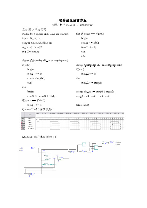
硬件描述语言作业杨帆电子0502班012005015324 五分频verilog代码:module fre_5_div(clk_in,clk_out,r_clk_out,ena); input clk_in,ena;output clk_out,r_clk_out;reg temp1,temp2;reg [2:0]count;always @(posedge clk_in or negedge ena) if(!ena)begintemp1 <= 0;count <= 3'b0;endelsebegincount <= count + 1'b1;if(count == 3'b010)temp1 <= 1; else if(count == 3'b100)begincount <= 3'b0;temp1 <= 0;endendalways @(negedge clk_in or negedge ena) if(!ena)temp2 <= 0;elsetemp2 <= temp1;assign clk_out = temp1 | temp2; assign r_clk_out = ~clk_out;endmoduleQuartusII v7.0仿真波形:Leonardo综合电路图如下:1101序列检测器verilog代码:module Moorefsm (clk,rst,a,z); input clk,rst;input a;output z;reg z;reg [3:0] currentstate,nextstate; parameter s0=4'b0000; parameter s1=4'b0001; parameter s2=4'b0010; parameter s3=4'b0011; parameter s4=4'b0100;always@(posedge clk or negedge rst) if(!rst)currentstate<=0;elsecurrentstate<=nextstate;always@(currentstate or a) case(currentstate)s0:nextstate=(a==1)?s1:s0;s1:nextstate=(a==0)?s2:s1;s2:nextstate=(a==1)?s3:s0;s3:nextstate=(a==1)?s4:s2;s4:nextstate=(a==1)?s1:s2;default:nextstate=s0; endcasealways@(rst or currentstate) if(!rst)z=0;else case (currentstate)s4:z=1;default:z=0;endcaseendmoduleQuartusII v7.0仿真波形如下:Leonardo 综合电路图如下:12小时计数器verilog代码如下:module clock(clk,rst,sec,mini,hour);input clk,rst;output [5:0]sec,mini,hour;reg [5:0]sec,mini,hour;reg [5:0]temp1,temp2,temp3;always@(posedge clk or negedge rst)if(!rst)begintemp1<=6'b0;temp2<=6'b0;temp3<=6'b0;endelsebegintemp1<=temp1+6'b1;if(temp1==6'b111011)begintemp1<=0; temp2<=temp2+6'b1;if(temp2==6'b111011)begintemp2<=0;temp3<=temp3+6'b1;if(temp3==6'b001011)temp3<=0;endendendalways@(temp1 or temp2 or temp3)beginsec=temp1;mini=temp2;hour=temp3;endendmoduleLeonardo综合电路图如下:。
硬件PRD模板范文
硬件PRD模板范文硬件产品PRD模板1.产品概述:在这一部分,简要介绍硬件产品的名称、功能和主要特点。
包括产品的定位、主要用户群体以及产品的核心竞争力。
2.需求背景:简要描述市场需求和用户需求,阐明为什么需要这款硬件产品。
可以结合数据分析市场规模、用户反馈等。
3.目标用户:详细描述产品的目标用户群体,包括用户的特征、使用场景和需求。
这部分需求与产品功能设计有密切关联。
4.产品功能:在这一部分,详细列出硬件产品的各项功能。
注意要细化功能,并与需求背景和目标用户保持一致。
5.产品规格:列出硬件产品的具体规格,包括尺寸、重量、材质等。
6.系统架构:描述硬件产品的系统架构,包括硬件组成和各部分之间的关系。
可以使用图表和示意图进行展示。
7.界面设计:描述硬件产品的界面设计,包括显示屏、按键、接口等。
可以结合视觉设计进行展示。
8.用户交互:详细描述用户和硬件产品之间的交互方式,包括按钮操作、手势识别等。
9.使用场景:描述用户在不同场景下使用硬件产品的情况,包括室内、户外、工作环境等。
10.系统要求:列出硬件产品的运行环境要求,包括操作系统、处理器、内存等。
11.安全防护:阐述硬件产品的安全防护措施,包括数据加密、指纹识别等。
12.故障排除:介绍硬件产品发生故障时的排查和解决办法。
13.售后服务:详细描述售后服务内容和方式,包括维修、退换货政策等。
14.附录:包括产品原理图、尺寸图、电路图等相关附件。
以上是硬件产品PRD的主要内容和模板。
根据具体产品的特点和需求,可以适当增减相关内容。
在编写PRD时,要结合市场调研和用户需求,确保产品的功能和特点能够满足用户的需求,提升产品竞争力。
计算机硬件介绍英语作文

计算机硬件介绍英语作文## What is computer hardware?##。
Computer hardware is the physical components of a computer system. It includes all the electronic devicesthat make up the computer, as well as the physical devices that allow the computer to function. The hardware components of a computer system can be divided into two main categories: internal components and external components.Internal components are the components that are located inside the computer case. These components include the motherboard, processor, memory (RAM), storage devices (hard drives and solid-state drives), and graphics card. The motherboard is the main circuit board of the computer andit connects all of the other internal components. The processor is the brain of the computer and it is responsible for executing instructions. Memory (RAM) stores the instructions and data that are being processed by theprocessor. Storage devices store the operating system, applications, and files. The graphics card is responsiblefor displaying images on the monitor.中文回答:计算机硬件是计算机系统中的物理组件,它包括组成计算机的所有电子设备以及实现计算机功能的物理设备,计算机系统的硬件组件可分为: 内部组件和外部组件。
硬件描述语言VHDLPPT精选文档
END kxor;
ENTITY、IS、PORT、IN、OUT和END为关键字; ENTITY...END之间表示实体内容; kxor表示实体的名称,即电路的符号名; PORT——端口(引脚)信息关键字,描述了信号的流向; std_logic表示信号取值的类型为标准逻辑。
1. entity实体描述格式
entity 实体名 is
[generic(类属表);]
[port(端口表);]
[declarations说明语句;]
[begin
实体语句部分];
end [实体名];
[ ]表示其中的部分是可选项。 10
1. entity实体描述格式
实体语句的一般格式 ENTITY 实体名 IS
y: out bit);
--输出信号:y,为bit数据类型
end mux21;
--实体描述结束
13
3.类属表 类属表:描述的是实体与外界通信的静态信息通道。类属表主 要用来规定端口的大小,实体中元件的数目,实体的定时特性 等。通常放在端口语句之前。 类属表的书写格式:
generic ([常量]名字表:[in]类属标识[:=初始值];…); 例如:generic(wide:integer:=32);
15
Out与Buffer的区别
Entity test1 is port(a: in std_logic; b,c: out std_logic ); end test1;
architecture a of test1 is begin
b <= not(a); c <= b;--Error end a;
介绍PC硬件的英语作文

介绍PC硬件的英语作文Title: An Overview of PC Hardware Components。
Introduction:In the realm of computing, understanding the fundamental components of a personal computer (PC) is crucial. These components work in harmony to execute tasks efficiently. In this essay, we will delve into the various hardware components that constitute a typical PC.Central Processing Unit (CPU):The CPU serves as the brain of the computer, executing instructions and performing calculations. It comprises arithmetic logic units (ALUs), control units, and registers. Modern CPUs have multiple cores, allowing for parallel processing and improved performance.Random Access Memory (RAM):RAM is temporary storage used to store data and instructions that the CPU needs to access quickly. It is volatile memory, meaning it loses its contents when the power is turned off. RAM capacity significantly impacts a computer's multitasking ability and overall responsiveness.Motherboard:The motherboard is the main circuit board that connects all other components of the PC. It houses the CPU, RAM, storage devices, and expansion cards. It also facilitates communication between these components via buses and ports.Storage Devices:Storage devices store data permanently or semi-permanently. Hard Disk Drives (HDDs) use spinning magnetic disks to store data, while Solid State Drives (SSDs)utilize flash memory for faster read/write speeds. SSDs are becoming increasingly popular due to their speed and reliability.Graphics Processing Unit (GPU):The GPU is responsible for rendering images, videos, and animations. It offloads graphical tasks from the CPU, improving overall system performance, especially in gaming and multimedia applications. GPUs have their dedicated memory called Video RAM (VRAM).Power Supply Unit (PSU):The PSU converts electrical power from the outlet into a form suitable for the computer's internal components. It provides stable voltages to ensure the proper functioning of the CPU, GPU, and other hardware components.Cooling System:To prevent overheating, PCs utilize cooling systems such as fans, heat sinks, and liquid cooling solutions. These components dissipate heat generated by the CPU, GPU, and other high-power hardware, ensuring stable operationand prolonging component lifespan.Input and Output Devices:Input devices like keyboards, mice, and touchscreens allow users to interact with the computer, while output devices such as monitors, printers, and speakers display information or produce output generated by the computer.Expansion Cards:Expansion cards are additional circuit boards inserted into expansion slots on the motherboard. Common expansion cards include graphics cards, sound cards, and network interface cards, which enhance the capabilities of the computer.Conclusion:Understanding the various hardware components of a PC is essential for anyone interested in computing. Each component plays a vital role in the overall performance andfunctionality of the system. By comprehending these components and their functions, users can make informed decisions when building or upgrading their PCs.。
硬件描述语言

硬件描述语言期末作业分析题目:出租车计价器专业:电子信息工程学生:段晨阳、梁佳佳、段晨阳、栾世达、李俊杰学号: 201142363、201142238、201142282、201142344总体方案设计一设计要求该出租车计价器实现功能:1、行程≤4公里,且等待累计时间≤2分钟,起步费为8.0元。
2、行程4公里外,以每公里1.0元,等待累计时间2分钟外,以每分钟以1.0元计费。
3、能显示行驶公里数、等待累计时间和最后的总费用。
4、能通过修改程序来对计费要求实现改变。
用Verilog HDL语言设计符合上述功能要求的出租车计费器,并用层次化设计方法设计该电路,各计数器的计数状态用功能仿真的方法验证,并通过有关波形确认电路设计是否正确。
方案论证采用EDA技术,根据层次化设计理论,该设计问题自顶向下可分为分频模块,控制模块计量模块、译码和动态扫描显示模块,其系统框图如图所示:二设计思想及原理出租车的一般计费过程为:出租车载客后,启动计费器,整个系统开始运行,里程计数器和时间计数器从0开始计数,费用计数器从8开始计算。
再根据行驶里程或停止等待的时间按以上的标准计费。
若在行驶状态,则计程器开始加计数,当路程超过四公里后,计费器以每公里1元累加。
若出租车停止等待状态,则计时器开始加计数,当时间超过两分钟后,计费器以每分钟1元累加。
出租车到达目的地停止后,停止计费器,显示总费用。
根据课程设计要求计价器可根据车轮转数计算路程,车轮每转一圈送一个脉冲波,假设每转一圈为2米,车轮每转一圈送一个脉冲波( 可用传感器检测送出脉冲),本设计为了好模拟仿真假设的是车轮转动100圈才产生一个脉冲,即是一个脉冲是代表200米,则经过5分频器后是每1Km送一个脉冲到里程计算模块,这样方便在软件里面仿真观察,若要下载到实物应用中去,通过实际车轮周长自己设置不同的分频电路来达到产生任意精度的计程距离模块。
而当车停止的时候通过分频模块产生秒脉冲,通过计时要求来产生计费,本设计重点就在计费控制模式模块和计费模块这两大模块的设计,则根据出租车计费器的工作过程,本系统采用分层次、分模块的方式设计。
电脑硬件介绍范文
电脑硬件介绍范文电脑硬件是指构成电脑主体的各个组成部分,包括中央处理器(CPU)、主板、内存、硬盘、显卡、显示器、键盘、鼠标等。
在这篇文章中,我将为您详细介绍每个硬件组件的功能和作用。
首先,让我们来看看中央处理器(CPU)。
中央处理器是电脑的大脑,它负责执行和控制整个计算机系统的各种操作。
CPU的速度决定了计算机的运行速度和处理能力。
现在流行的CPU厂商有英特尔和AMD,它们生产了各种不同型号和系列的处理器,以满足不同用户的需求。
接下来是主板,也称为系统板或母板。
主板是电脑系统的核心组件,它提供了连接各种硬件设备的接口和插槽。
主板上有集成电路、追踪线路和连接器,用来连接中央处理器、内存、硬盘、显卡等各个硬件组件。
主板的质量和性能直接影响着计算机的稳定性和速度。
内存是存储数据和程序的地方,它是电脑中的临时存储器。
内存通常分为主内存和辅助内存,主内存是CPU直接访问的存储器,辅助内存是用来存储大容量数据和程序的设备,如硬盘、固态硬盘等。
内存的大小决定了计算机可以同时处理的任务数量和运行程序的速度。
硬盘是用来存储数据的设备,它通常是计算机中最大容量的存储器。
硬盘有机械硬盘(HDD)和固态硬盘(SSD)两种类型。
机械硬盘使用磁性材料和机械运动的方式来存储和访问数据,而固态硬盘则使用闪存存储器来实现数据的存储和访问。
固态硬盘的读写速度比机械硬盘快很多,因此越来越受到用户的青睐。
显卡是负责显示图像和图形的设备,它的性能直接影响计算机的图像处理能力和游戏性能。
显卡有独立显卡和集成显卡两种类型。
独立显卡是一种独立于主板的显卡,它有自己的显存和处理器,可以提供更好的图像处理性能。
集成显卡则是集成在主板上的显卡,它的性能比较低,适合一般办公和娱乐使用。
显示器是电脑输出图像和文字的设备,它通过显示技术将计算机处理的数据转化为可视化的图像。
显示器通常由液晶显示屏或LED显示屏组成,其尺寸和分辨率决定了显示效果的清晰度和细腻程度。
计算机硬件介绍英语作文
计算机硬件介绍英语作文Title: Introduction to Computer Hardware.In the modern era of technology, computer hardware serves as the backbone of all digital devices, enabling them to perform various tasks efficiently. Computer hardware refers to the physical components that constitute a computer system, including the input/output devices, central processing unit (CPU), memory, storage devices, and other internal components. This article aims to provide a comprehensive introduction to computer hardware, exploring its various components, functions, and significance in today's digital world.Firstly, let's delve into the central processing unit (CPU), the brain of the computer. The CPU is responsiblefor executing instructions and performing calculations, ensuring the smooth operation of the computer. It consists of the arithmetic logic unit (ALU), which performs arithmetic and logical operations, and the control unit(CU), which manages the flow of instructions. The speed and performance of a CPU are determined by its clock speed, cache memory, and the number of cores it possesses. Modern CPUs often feature multi-core architectures, allowing them to handle multiple tasks simultaneously, enhancing overall computing efficiency.Memory, also known as RAM (Random Access Memory), serves as the temporary storage space for data and instructions required by the CPU. RAM is.。
硬件描述语言及器件2(侯伯亨版)
硬件描述语言发展历程
1980年代
第一个HDL,即VHDL诞生。
1990年代
Verilog成为另一种广泛使用的 HDL。
2000年代至今
随着FPGA和ASIC设计复杂性的 增加,HDL在数字电路设计中占 据越来越重要的地位。
硬件描述语言应用领域
集成电路设计
用于描述数字集成电路的行为和结构。
系统级设计
述组合逻辑电路和时序逻辑电路,使得设计者能够更方便地描述电路的行为和功能。
结构建模
总结词
结构建模关注电路的物理结构和组成,使用实例化语句来描述。
详细描述
结构建模是一种基于物理结构的硬件描述方法。它关注电路的物理结构和组成,使用实例化语句来描述电路的各 个组成部分。这种方法使得设计者能够更清晰地表达电路的结构和组成,并且方便地实现电路的模块化和复用。
仿真和测试
Verilog支持仿真和测试,使得设计者能够验证电路的正确性和性能。
可移植性
Verilog代码可以在不同的EDA工具和平台上使用,提高了设计的可 移植性。
模块化设计
Verilog支持模块化设计,使得复杂系统可以被分解为较小的模块, 提高了设计的可维护性和可重用性。
Verilog语言基本结构
混合建模
总结词
混合建模结合了行为建模和结构建模的方法,通过使用不同的建模方法来描述不同的电路部分。
详细描述
混合建模是一种综合使用行为建模和结构建模的方法。它可以根据不同的电路部分选择不同的建模方 法,以实现更全面、更准确的硬件描述。混合建模能够充分发挥行为建模和结构建模的优势,使得设 计者能够更灵活地描述复杂的电路系统。
05
硬件描述语言应用实例
VHDL应用实例
硬件描述语言介绍
2选1数据选择器及仿真研究
21 (); ; s; y; y = (0)? a : b;
1. 语句 2. 表达式1? 表达式2: 表达式3
s
b
0
y
a
1
y~0
数据流描述
21 (); ; s; y; ; d = a & (); e = b & s; y = d | e;
1 2
&0 1 x z 00000 101xx x0xxx z0xxx
| 0 1 xz 0 0 1 xx 1 1 1 11 x x 1 xx z x 1 xx
~ 01 10 xx zx
^0 1xz 0 0 1xx 1 1 0xx xXxxx z X x xx
^~ 0 1 x z 010xx 101xx xxxxx z x x xx
行为级描述
的行为可以描述为:只要信号a或b或s发生变化,如果s为0则选择a输 出;否则选择b输出。
输延时。
21(, a, b, ); a, b, ; ;
u1 (, ); #1 u2 (, a, ); #1 u3 (, b, );
#2 u4 (, , );
4选1数据选择器实例之一
4_1(0123); ; 0123; [1:0] ; ; @(0 1 2 3 ) () 2'b00: 0; 2'b01: 1; 2'b10: 2; 2'b11: 3; :;
a = b c; b = a c; a < b -1
(! ) (a<1)()()
( 0)
结构型描述
结构级适合开发小规模元件,如和的单元 内部带有描述基本逻辑功能的基本单元(),如门。 综合产生的结果网表通常是结构级的。用户可以用结构级描述
- 1、下载文档前请自行甄别文档内容的完整性,平台不提供额外的编辑、内容补充、找答案等附加服务。
- 2、"仅部分预览"的文档,不可在线预览部分如存在完整性等问题,可反馈申请退款(可完整预览的文档不适用该条件!)。
- 3、如文档侵犯您的权益,请联系客服反馈,我们会尽快为您处理(人工客服工作时间:9:00-18:30)。
硬件描述语言语言设计实例1、8-3编码器module encode_verilog ( a ,b );input [7:0] a ; //编码器输入wire [7:0] a ;output [2:0] b ; //编码器输出reg [2:0] b;always @ ( a )begincase ( a ) //编码器某一输入端口为高电平输出相应的3位二进制数8'b0000_0001 : b<=3'b000; //08'b0000_0010 : b<=3'b001; //18'b0000_0100 : b<=3'b010; //28'b0000_1000 : b<=3'b011; //38'b0001_0000 : b<=3'b100; //48'b0010_0000 : b<=3'b101; //58'b0100_0000 : b<=3'b110; //68'b1000_0000 : b<=3'b111; //7default : b<= 3'b000; //其他情况编码器输出3’b000endcaseendendmodule2、8-3优先编码器module p_encode_verilog ( A ,I ,GS ,EO ,EI ); //编码器以低为有效input [7:0] I ; //编码器输入wire [7:0] I ;input EI ; //输入使能,EI=0时,编码器正常工作wire EI ;output [2:0] A ; //编码器输出reg [2:0] A ;output GS ; //优先编码器工作状态标志,编码器的八个输入端有信号输入时,GS=0 reg GS ;output EO ; //输出使能,reg EO ;always @ ( I or EI )if ( EI ) //使用if、else if表明条件的优先级顺序beginA <= 3'b111;GS <= 1;EO <= 1;endelse if ( I[7] == 0 )beginA <= 3'b000;GS <= 0;EO <= 1;endelse if ( I[6] == 0 )beginA <= 3'b001;GS <= 0;EO <= 1;endelse if ( I[5] == 0 )beginA <= 3'b010;GS <= 0;EO <= 1;endelse if ( I[4] == 0 )beginA <= 3'b011;GS <= 0;EO <= 1;endelse if ( I[3] == 0 )beginA <= 3'b100;GS <= 0;EO <= 1;endelse if ( I[2] == 0 )beginA <= 3'b101;GS <= 0;EO <= 1;endelse if ( I[1] == 0 )beginA <= 3'b110;GS <= 0;EO <= 1;endelse if ( I[0] == 0 )beginA <= 3'b111;GS <= 0;EO <= 1;endelse if ( I == 8'b11111111)beginA <= 3'b111;GS <= 1;EO <= 0;endendmodule3、3-8译码器module decoder_verilog ( G1 ,Y ,G2 ,A ,G3 ); input G1 ; //使能输入,高有效wire G1 ;input G2 ; //使能输入,低有效wire G2 ;input [2:0] A ; //3位译码器输入,为高有效wire [2:0] A ;input G3 ; //使能输入wire G3 ; //使能输入,低有效output [7:0] Y ; //8位译码器输出,为低有效reg [7:0] Y ;reg s;always @ ( A ,G1, G2, G3)begins <= G2 | G3 ;if ( G1 == 0) //G1为低有效Y <= 8'b1111_1111;else if ( s)Y <= 8'b1111_1111;elsecase ( A )3'b000 : Y<= 8'b1111_1110;3'b001 : Y<= 8'b1111_1101;3'b010 : Y<= 8'b1111_1011;3'b011 : Y<= 8'b1111_0111;3'b100 : Y<= 8'b1110_1111;3'b101 : Y<= 8'b1101_1111;3'b110 : Y<= 8'b1011_1111;3'b111 : Y<= 8'b0111_1111;endcaseendendmodule4、数据选择器module mux8_1_verilog ( Y ,A ,D0, D1,D2, D3, D4, D5, D6, D7 ,G );input [2:0] A ; //地址输入端wire [2:0] A ;input D0 ; //数据输入端input D1 ; //数据输入端input D2 ; //数据输入端input D3 ; //数据输入端input D4 ; //数据输入端input D5 ; //数据输入端input D6 ; //数据输入端input D7 ; //数据输入端input G ; //使能端,当G=1时Y=0,当G=0时数据选择器正常工作wire G ;output Y ; //数据输出端reg Y ;always @(G or A or D0 or D1 or D2 or D3or D4 or D5 or D6 or D7 )beginif (G == 1) //使能端的优先级高Y <= 0;elsecase (A ) //根据输入的地址A确定数据选择器输出哪路输入数据3'b000 : Y = D0 ;3'b001 : Y = D1 ;3'b010 : Y = D2 ;3'b011 : Y = D3 ;3'b100 : Y = D4 ;3'b101 : Y = D5;3'b110 : Y = D6 ;3'b111 : Y = D7 ;default : Y = 0;endcaseendendmodule5、多位数值比较器module compare_verilog ( Y ,A ,B );input [3:0] A ; //4位二进制数Awire [3:0] A ;input [3:0] B ; //4位二进制数Bwire [3:0] B ;output [2:0] Y ; //A与B大小的比较结果reg [2:0] Y ;always @ ( A or B )beginif ( A > B )Y <= 3'b001; //A > B时Y输出3'b001 else if ( A == B)Y <= 3'b010; //A = B时Y输出3'b010 elseY <= 3'b100; //A < B时Y输出3'b100 endendmodule6、全加器module sum_verilog ( A ,Co ,B ,S ,Ci );input A ; //输入加数Awire A ;input B ; //输入加数Bwire B ;input Ci ; //相邻低位的进位输入信号wire Ci ;output Co ; //向相邻高位的进位输出信号reg Co ;output S ; //相加和数输出reg S ;always @ ( A or B or Ci)beginif ( A== 0 && B == 0 && Ci == 0 )beginS <= 0;Co <= 0;endelse if ( A== 1 && B == 0 && Ci == 0 )beginS <= 1;Co <= 0;endelse if ( A== 0 && B == 1 && Ci == 0 )beginS <= 1;Co <= 0;endelse if ( A==1 && B == 1 && Ci == 0 )beginS <= 0;Co <= 1;endelse if ( A== 0 && B == 0 && Ci == 1 )beginS <= 1;Co <= 0;endelse if ( A== 1 && B == 0 && Ci == 1 )beginS <= 0;Co <= 1;endelse if ( A== 0 && B == 1 && Ci == 1 )beginS <= 0;Co <= 1;endelsebeginS <= 1;Co <= 1;endendendmodule7、D触发器module Dflipflop ( Q ,CLK ,RESET ,SET ,D ,Qn );input CLK ; //D触发器输入时钟wire CLK ;input RESET ; //D触发器清零输入wire RESET ;input SET ; //D触发器预置数输入wire SET ;input D ; //D触发器输入wire D ;output Q ; //D触发器输出reg Q ;output Qn ;wire Qn ;assign Qn = ~Q ; //将D触发器输出取反always @ ( posedge CLK or negedge SET or negedge RESET ) beginif ( !RESET) //RESET下降沿将D触发器输出清零Q <= 0 ;else if ( ! SET) //SER下降沿将D触发器输出置1 Q <= 1;else Q <= D; //CLK上升沿D触发器输出等于输入endendmodule8、寄存器module reg8 ( clr ,clk ,DOUT ,D );input clr ; //异步清零信号,高有效wire clr ;input clk ; //时钟输入wire clk ;input [7:0] D ; //寄存器数据输入wire [7:0] D ;output [7:0] DOUT ; //寄存器数据输出reg [7:0] DOUT ;always @ ( posedge clk or posedge clr)beginif ( clr == 1'b1)DOUT <= 0;else DOUT <= D ;endendmodule9、双向移位寄存器module shiftdata ( left_right ,load ,clr ,clk ,DIN ,DOUT );input left_right ; // 左移右移控制信号wire left_right ;input load ; //异步置数信号,有效时将DIN输入wire load ;input clr ; //异步清零信号,高有效wire clr ;input clk ; //时钟输入wire clk ;input [3:0] DIN ; //并行输入wire [3:0] DIN ;output [3:0] DOUT ; //并行输出wire [3:0] DOUT ; // DOUT是一个wire型变量,不能在always块中被赋值reg [3:0] data_r; //所以定义一个寄存器型变量data_r作为中间变量assign DOUT = data_r ;always @ ( posedge clk or posedge clror posedge load )beginif ( clr == 1) //异步清零data_r <= 0;else if (load ) //异步置数data_r <= DIN;else beginif ( left_right) //left_right=1,信号左移begindata_r <= (data_r<<1);data_r[0] <= 0; //移出位补0endelse begin //left_right=0,信号右移data_r <= (data_r>>1);data_r[3] <= 0; //移出位补0endendendendmodule10、4位二进制加减法计数器module counter4 ( load ,clr ,c ,DOUT ,clk, up_down ,DIN);input load ; //异步预置数input clk; //输入时钟wire load ;input clr ; //异步清零wire clr ;input up_down ; //加减计数,up_dpwn=1加计数,up_down=0减计数wire up_down ;input [3:0] DIN ; //预置数输入wire [3:0] DIN ;output c ; //进位/借位输出,可以用于计数器的级联reg c ;output [3:0] DOUT ; //计数输出wire [3:0] DOUT ;reg [3:0] data_r;assign DOUT = data_r;always @ ( posedge clk or posedge clror posedge load)beginif ( clr == 1) //异步清零data_r <= 0;else if ( load == 1) //异步预置data_r <= DIN;else begin if ( up_down ==1) //加计数beginif ( data_r == 4'b1111) begindata_r <= 4'b0000;c = 1;endelse begindata_r <= data_r +1;c = 0 ;endendelse //减计数beginif ( data_r == 4'b0000) begindata_r <= 4'b1111;c = 1;endelse begindata_r <= data_r -1;c = 0 ;endendendendendmodule11、十进制加减法计数器module counter10 ( load ,clr ,c ,DOUT ,clk,up_down ,DIN ,seven_seg);input load ; //异步预置数input clk; //输入时钟wire load ;input clr ; //异步清零wire clr ;input up_down ; //加减计数,up_dpwn=1加计数,up_down=0减计数wire up_down ;input [3:0] DIN ; //预置数输入wire [3:0] DIN ;output c ; //进位/借位输出,可以用于计数器的级联reg c ;output [3:0] DOUT ; //计数输出output [7:0] seven_seg; //7段数码管wire [3:0] DOUT ;reg [3:0] data_r;assign DOUT = data_r;always @ ( posedge clk or posedge clror posedge load)beginif ( clr == 1) //异步清零data_r <= 0;else if ( load == 1) //异步预置data_r <= DIN;else if ( up_down ==1 & data_r == 9) //加进位beginc = 1;data_r <= 4'b0000;endelse if ( up_down ==0 & data_r == 0) //减借位beginc = 1;data_r <= 9;endelsebeginif (up_down ==1) begin //加计数data_r <= data_r +1;c = 0 ;endelse begin //减计数data_r <= data_r -1 ;c = 0 ;endendend/************数码管***************/assign seven_seg =Y_r;reg [7:0] Y_r;always @(data_r ) //用7段数码管显示计数输出beginY_r =8'b11111111;case (data_r )4'b0000: Y_r = 8'b00000011; //显示04'b0001: Y_r = 8'b10011111; //显示14'b0010: Y_r = 8'b00100101; //显示24'b0011: Y_r = 8'b00001101; //显示34'b0100: Y_r = 8'b10011001; //显示44'b0101: Y_r = 8'b01001001; //显示54'b0110: Y_r = 8'b01000001; //显示64'b0111: Y_r = 8'b00011111; //显示74'b1000: Y_r = 8'b00000001; //显示84'b1001: Y_r = 8'b00001001; //显示9default: Y_r = 8'b11111111; //默认数码管不发光endcaseendendmodule12、顺序脉冲发生器module pulsegen ( Q ,clr ,clk);input clr ; //异步预置数wire clr ;input clk ; //时钟输入wire clk ;output [7:0] Q ;//顺序脉冲输出wire [7:0] Q ;reg [7:0] temp ;reg x;assign Q =temp;always @ ( posedge clk or posedge clr )beginif ( clr==1)begintemp <= 8'b00000001; //temp寄存预定的序列x= 0 ;endelsebeginx<= temp[7] ; //序列最高位输出temp <= temp<<1 ; //temp左移一位temp[0] <=x; //将输出的结果赋给序列最低位,实现序列的循环输出endendendmodule13、序列信号发生器module xlgen ( Q ,clk ,res);input clk ; //时钟输入wire clk ;input res ; //异步预置数wire res ;output Q ; //序列信号输出reg Q ;reg [7:0] Q_r ;always @( posedge clk or posedge res)beginif (res ==1)beginQ <= 1'b0;Q_r <= 8'b11100100 ;//Q_r寄存预定的序列endelsebeginQ <= Q_r[7]; //序列最高位输出Q_r <= Q_r<<1; //Q_r左移一位Q_r[0] <=Q; //将输出的结果赋给序列最低位,实现序列的循环输出endend endmodule14、分频器module clockdiv ( Q ,rst ,sysclk ,sel );input rst ; //系统复位wire rst ;input sysclk ; //系统时钟输入wire sysclk ;input [1:0] sel ; //分频倍数选择wire [1:0] sel ;output Q ; //分频器输出wire Q ;reg [2:0] q;reg [31:0] cnt ;reg clk ;//时钟分频模块always @( posedge sysclk or negedge rst)beginif ( !rst ) begincnt <= 0 ;clk <= 1'b1 ;endelse begincnt <= cnt + 1'b1 ;if (cnt >= 32'd2500000 ) begin /clk时钟周期是系统时钟周期的5000000倍clk <= ~clk;cnt <= 0 ;endendend//分频器模块always @ ( posedge clk or negedge rst )if ( !rst ) q[0] <= 0;else q[0] <= ~q[0] ; // q[0]是clk的2分频always @ ( posedge q[0] or negedge rst )if ( !rst ) q[1] <= 0;else q[1] <= ~q[1] ; // q[1]是clk的4分频always @ ( posedge q[1] or negedge rst )if ( !rst ) q[2] <= 0;else q[2] <= ~q[2] ; // q[2]是clk的8分频assign Q = (sel== 2'd0) ? clk : //分频器输出clk(sel== 2'd1) ? q[0] : //分频器输出clk的二分频(sel== 2'd2) ? q[1] : //分频器输出clk的四分频(sel== 2'd3) ? q[2] : 0; //分频器输出clk的八分频endmodule。