中英文文献翻译-汽车转向系统
机械类汽车转向系统外文文献及翻译

1 IntroductionThe key task for the automobile industry and its suppliers in future lies in speedily developing and implementing ecologically sound and economically justifiable mobility systems. Light metals such as aluminum and magnesium along with glass and carbon fiber reinforced materials, ceramics and composites have opened up the potential for considerable weight reduction and for "green" vehicle concepts which can be realized economically. Aluminum in particular can provide the impetus for new designs for the next millennium. Decades ago, the use of aluminum in auto construction was seen as an "experiment"; Today it is a vital factor in reducing weight and thus lowering fuel consumption.The average passenger car today contains 60 to 70 kg of aluminum, and current developments point to a doubling of this amount in the next few years. Motor vehicles both now and in future must meet requirements for: greater performance, greater safety, comfort, low pollution. Lightweight construction is not just about reducing weight; it is a question of -striking the right balance between reduced weight and structural efficiency. In vehicle construction this normally means making the best use of the generally very tight space available for individual components so as to allow weight to be minimized while still meeting all stiffness, strength, natural frequency or acoustical requirements. To achieve this, stresses must be distributed throughout the structure as evenly as possible. Modern numerical analysis methods such as FEA allow a very detailed analysis of system behavior, provide cost-efficient support for the complex process of optimization and thus make a huge contribution to advances in lightweight construction. Packaging, safety considerations, reproducibility and price place restrictions on the degree of weight reduction achievable.The broad range of expertise available to Krupp Presta AG allows the company to analyze customer specifications for steering systems and provide appropriate solutions.2 Requirements to be met by steering systemsThe steering is an important part of the feel of a car. The steering system should make driving an enjoyable experience with no unpleasant vibration from the road surface while guaranteeing the required hand- sing. It is also important that high safety requirements be met, both under normal conditions and in crash situations. The key criteria for the steering system are thus as follows:rolling friction, torsional stiffness /strength, Damping, temperature, corrosion, durability / fatigue, weight. Crash kinematics and energy absorption steering column requirements:natural frequency / stiffness, mass, damping, space, strength (crash, misuse), ergonomics, handling, acoustics, crash kinematics and energy absorption. Other basic conditions:interfaces with adjacent components, installation, joining techniques, price.3 Materialsmaterial light weighting can be achieved by using either stronger or lighter material. When stiffness or natural frequency are Important sizing criteria, low density materials with a high modulus of elasticity by quired. Non-exotic materials must be selected which are readily recyclable, low in price and display good durability.Further requirements are set by the manufacturing and joining processes. Steel, aluminum, magnesium and a variety of plastics are the materials of choice for steering systems.Low specific gravity, high corrosion resistance, low fabricating costs, high energy absorption and good recycle ability make aluminum a favored light weighting material. Owing to its high energy content, up to 90% of the aluminum used in auto construction can be recycled (intelligent design / no mixing with other materials). The favorable energy balance of aluminum puts it at a great advantage over many other materials.In environmental terms aluminum scores highly. The large amounts of primary energy required to make raw aluminum are offset over the lifetime of the vehicle. Composites could also become a very attractive proposition on account of their extreme stiffness, low weight and energy absorption capabilities. At present, howler, price is a problem, as are joining and quality assurance.4 Reducing component weightA focused strategy to reduce component weight requires a lightweight approach to design (force distribution, stresses), material (material selection), specifications (modified, realistic specifications)Key factors in lightweight design include [1]: force flows, material properties, ambient conditions ® safety requirements, reliability of joints, manufacture ability. Practical experience has shown that car makers' specifications based on steel need to be revised for lightweighting. Requirements valid for a steel steering shaft, for example, can result in severe oversizing of an aluminum shaft. Reducing component weight requires material compatible designs combined with material- compatible specifications.5 Lightweight componentsAs part of its development program Krupp Presta is replacing conventional steel steering components such as steering rods , shafts or forks with corresponding aluminum components produced by new processes. Weight savings of 20-30% are achievable depending on the basic conditions stipulated by the customer. Aluminum and magnesium die castings are already being used in steering columns , and further opportunities for weight reduction are being investigated. The lightweight steering column (Fig. 1) produced by Krupp Presta for the Audi A6 is a good example. By using magnesium die castings it has been possible to limit the weight of the steering column to just 5kg, a reduction of 15-20% over conventional (steel) designs.6 Steering column designExperience has shown that it is possible to design steering columns for cars more or less on the basis of their natural frequency alone. Additional engineering work may be required to design critical parts which must not break in the case of a crash or misuse (e.g. theft). The main task when engineering a steering column is thus to achieve the highest possible natural frequencies while minimizing weight. Low-stiffness components are being analyzed and refined in an effort to achieve uniform loading of the structure. In solving this task, use is made of numerical methods such as FEA. The structure is divided into finite elements which are characterized by specific deformation assumptions. Using FE analysis it is possible to examine complex structures, analyze sensitivities and links, discuss variations or ways of making improvements and optimize the structure numerically. Topological optimization is carried out for the analysis of low-stress areas and for the basic design of ribs and beads. CAD geometrydata are processed in an FE pre-processor. Correct modeling of the following is essential, individual parts, stiffness, contact faces, kinematics mass. Modeling is followed by computation and evaluation of the data obtained. The deformation energy is a global measure for assessing stresses. Normalizing the element deformation energy by the element mass provides information on the stresses acting on the element relative to its mass. The kinetic energy is regarded as the influence of vibrating masses which have a negative effect on the natural frequency of the steering column. By evaluating stress and strain conditions, highly localized weak points or high-stress areas can be identified.7 ConclusionsExisting technologies must be continuously adapted and improved in line with the requirements of the auto industry. Systematic weight reduction is a major challenge and requires close cooperation between vehicle manufacturers and suppliers. Materials, fabricating and joining technologies must be further refined. One prerequisite for the continuing success of Krupp Presta is the flexibility to react to customer wishes and requirements.Reference[1] Klein, B.:Leichtbau-Konstruktion. Berech- nungsgrundlagen und Gestaltung.Braunschweig: Vieweg, 1997一、简介一、简介 汽车工业及其供应商,在未来的关键任务在于迅速制定和实施无害生态和经济上合理流动系统。
汽车转向系统中文文献

DSP-based电力辅助转向使用无刷直流电机MURUGAN NANDAKUMAR R,S和M S MOHIYADEENBharat Electronics Limited, Nandambakkam, Chennai 600 089e-mail: muruganr@bel.co.in; nandakumars@bel.co.in;mohiyadeenms@bel.co.in本文介绍了电的设计方法和步骤辅助动力转向系统(简称EAS)用无刷直流电机为一辆汽车。
控制建筑由两层控制,即车辆速度相关的控制以及扭矩协助控制。
在更高的层次上控制系统的体系结构、功能的车辆作为援助速度控制器、液位控制器的控制力。
在较低的水平,给出了转矩控制器的努力水平的控制。
这已经是实现了由扭矩传感器和车辆在DSP这种传感器。
为实现在系统中,DSP-based三相逆变器直流无刷电动机控制器模块是特意使用采用霍尔传感器反馈和一个单一的dc-link电流传感器。
这项工作是实现光商用车拥有一个循环球式齿轮。
这是第一次(简称EAS)的实施为这种类型的车辆在任何地方在世界上。
一般来说,有离合器递归断开电动机在高速度或非正常条件下从齿轮箱。
在该实现电动机直接耦合到变速箱没有离合器和所有的人异常处理的处理器。
这是执行,不修改车辆供应系统,比如改变现有的交流发电机或额定值电池,利用现有的传感器。
设计是这样一种方式的那种感觉司机援助可以变换轻易地在任何时间。
控制的性能实验结果表明,系统是它被测试在其中的轻型商用车辆(LCV)。
关键词。
无刷直流电机;EAS;转向系统。
1.介绍动力转向系统的转向努力降低车辆的使用外部的源,来协助将轮子。
现在大多数新一代车辆动力转向,由于车辆的趋势,走向更大质量和更宽的轮胎,所有增加的控制力所需要的。
现代交通工具很难动作,速度较低(例如当停车场)如果没有人帮助。
大多数助力转向系统工作,用皮带驱动泵提供的液压系统。
该液压压力泵,是所产生的车辆的引擎驱动。
汽车转向系统车辆外文文献翻译、中英文翻译、外文翻译
汽车转向系统随着汽车电子技术的迅猛发展,人们对汽车转向操纵性能的要求也日益提高。
汽车转向系统已从传统机械转向、液压助力转向(Hydraulic Power Steering ,简称HPS) 、电控液压助力转向( Electric Hydraulic PowerSteering , 简称EHPS) ,发展到电动助力转向系统(Electric Power Steering ,简称EPS) ,最终还将过渡到线控转向系统(Steer By Wire ,简称SBW)。
机械转向系统是指以驾驶员的体力作为转向能源,其中所有传力件都是机械的,汽车的转向运动是由驾驶员操纵方向盘,通过转向器和一系列的杆件传递到转向车轮而实现的。
机械转向系由转向操纵机构、转向器和转向传动机械3大部分组成。
通常根据机械式转向器形式可以分为:齿轮齿条式、循环球式、蜗杆滚轮式、蜗杆指销式。
应用最广的两种是齿轮齿条式和循环球式(用于需要较大的转向力时) 。
在循环球式转向器中,输入转向圈与输出的转向摇臂摆角是成正比的;在齿轮齿条式转向器中,输入转向圈数与输出的齿条位移是成正比的。
循环球式转向器由于是滚动摩擦形式,因而正传动效率很高,操作方便且使用寿命长,而且承载能力强,故广泛应用于载货汽车上。
齿轮齿条式转向器与循环球式相比,最大特点是刚性大,结构紧凑重量轻,且成本低。
由于这种方式容易由车轮将反作用力传至转向盘,所以具有对路面状态反应灵敏的优点,但同时也容易产生打手和摆振等现象,且其承载效率相对较弱,故主要应用于小汽车及轻型货车上,目前大部分低端轿车采用的就是齿轮齿条式机械转向系统。
随着车辆载重的增加以及人们对车辆操纵性能要求的提高,简单的机械式转向系统已经无法满足需要,动力转向系统应运而生,它能在驾驶员转动方向盘的同时提供助力,动力转向系统分为液压转向系统和电动转向系统2 种。
其中液压转向系统是目前使用最为广泛的转向系统。
液压转向系统在机械系统的基础上增加了液压系统,包括液压泵、V 形带轮、油管、供油装置、助力装置和控制阀。
汽车转向系统外文原文及翻译
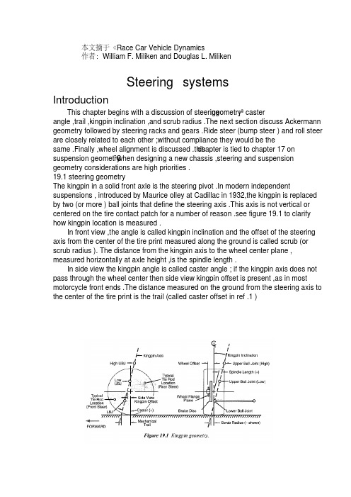
作者:William F. Miliken and Douglas L. MilikenSteering systemsIntroductionThis chapter begins with a discussion of steeringgeometry¡ªcasterangle ,trail ,kingpin inclination ,and scrub radius .The next section discuss Ackermann geometry followed by steering racks and gears .Ride steer (bump steer ) and roll steer are closely related to each other ;without compliance they would be thechapter is tied to chapter 17 onsame .Finally ,wheel alignment is discussed .this¨C when designing a new chassis ,steering and suspension suspension geometrygeometry considerations are high priorities .19.1 steering geometryThe kingpin in a solid front axle is the steering pivot .In modern independent suspensions , introduced by Maurice olley at Cadillac in 1932,the kingpin is replaced by two (or more ) ball joints that define the steering axis .This axis is not vertical or centered on the tire contact patch for a number of reason .see figure 19.1 to clarify how kingpin location is measured .In front view ,the angle is called kingpin inclination and the offset of the steering axis from the center of the tire print measured along the ground is called scrub (or scrub radius ). The distance from the kingpin axis to the wheel center plane , measured horizontally at axle height ,is the spindle length .In side view the kingpin angle is called caster angle ; if the kingpin axis does not pass through the wheel center then side view kingpin offset is present ,as in most motorcycle front ends .The distance measured on the ground from the steering axis to the center of the tire print is the trail (called caster offset in ref .1 )作者:William F. Miliken and Douglas L. MilikenSteering systemsIntroductionThis chapter begins with a discussion of steeringgeometry¡ªcasterangle ,trail ,kingpin inclination ,and scrub radius .The next section discuss Ackermann geometry followed by steering racks and gears .Ride steer (bump steer ) and roll steer are closely related to each other ;without compliance they would be thechapter is tied to chapter 17 onsame .Finally ,wheel alignment is discussed .this¨C when designing a new chassis ,steering and suspension suspension geometrygeometry considerations are high priorities .19.1 steering geometryThe kingpin in a solid front axle is the steering pivot .In modern independent suspensions , introduced by Maurice olley at Cadillac in 1932,the kingpin is replaced by two (or more ) ball joints that define the steering axis .This axis is not vertical or centered on the tire contact patch for a number of reason .see figure 19.1 to clarify how kingpin location is measured .In front view ,the angle is called kingpin inclination and the offset of the steering axis from the center of the tire print measured along the ground is called scrub (or scrub radius ). The distance from the kingpin axis to the wheel center plane , measured horizontally at axle height ,is the spindle length .In side view the kingpin angle is called caster angle ; if the kingpin axis does not pass through the wheel center then side view kingpin offset is present ,as in most motorcycle front ends .The distance measured on the ground from the steering axis to the center of the tire print is the trail (called caster offset in ref .1 )作者:William F. Miliken and Douglas L. MilikenSteering systemsIntroductionThis chapter begins with a discussion of steeringgeometry¡ªcasterangle ,trail ,kingpin inclination ,and scrub radius .The next section discuss Ackermann geometry followed by steering racks and gears .Ride steer (bump steer ) and roll steer are closely related to each other ;without compliance they would be thechapter is tied to chapter 17 onsame .Finally ,wheel alignment is discussed .this¨C when designing a new chassis ,steering and suspension suspension geometrygeometry considerations are high priorities .19.1 steering geometryThe kingpin in a solid front axle is the steering pivot .In modern independent suspensions , introduced by Maurice olley at Cadillac in 1932,the kingpin is replaced by two (or more ) ball joints that define the steering axis .This axis is not vertical or centered on the tire contact patch for a number of reason .see figure 19.1 to clarify how kingpin location is measured .In front view ,the angle is called kingpin inclination and the offset of the steering axis from the center of the tire print measured along the ground is called scrub (or scrub radius ). The distance from the kingpin axis to the wheel center plane , measured horizontally at axle height ,is the spindle length .In side view the kingpin angle is called caster angle ; if the kingpin axis does not pass through the wheel center then side view kingpin offset is present ,as in most motorcycle front ends .The distance measured on the ground from the steering axis to the center of the tire print is the trail (called caster offset in ref .1 )no diagonal weight jacking will occur .3. Caster angle affects steer-camber but ,unlike kingpin inclination ,the effect is favorable . With positive caster angle the outside wheel will camber in a negative direction (top of the wheel toward the center of the car ) while the inside wheel cambers in a positive direction , again learning into the turn .(steer out of the turn ) is used and in this case In skid recovery , ¨Dopposite lock ¡¬the steer¨Ccamber resulting from caster angle is in the ¨Dwrong ¡¬ direction for increased front tire grip . conveniently ,this condition results from very low lateral force at therear so large amounts of front grip are not needed .4. As discussed in chapter 2, tires have pneumatic trail which effectively adds to (and at high slip Angles subtracts from ) the mechanical trail . This tire effect is nonlinear with lateral force and affects steering torque and driver feel .In particular ,the fact that pneumatic trail approaches zero as the tire reaches the limit will result in lowering the self-centering torque and can be s signal to the driver that the tire is near breakaway .The pneumatic trail ¨Dbreakaway signal¡¬ will be swamped out by mechanical trail if the mechanical trail is large compared to the pneumatic trail .5.Sometimes the trail is measured in a direction perpendicular to the steering axis (rather than horizontal as shown in figure 19.1) because this more accurately describes the lever (moment ) arm that connects the tire lateral forces to the kingpin . Tie rod locationNote that in figure 19.1 a shaded area is shown for the steering tie rod location . Camber compliance under lateral force is unavoidable and if the tie rod is located as noted ,the effect on the steering will be in the understeer ( steer out of the turn ) direction becomes much more complex than can be covered here .19.2 Ackerman steering geometryAs the front wheels of a vehicle are steered away from the straight-aheadposition ,the design of the steering linkage will determine if the wheels stay parallel orif one wheel steers more than the other .This difference in steer Angles on the left and right wheels should not be confused with toe-in or toe-out which are adjustments and add to ( or subtract from ) Ackerman geometric effects .For low lateral acceleration usage (street cars) it is common to use Ackerman geometry . as seen on the left of figure 19.2, this geometry ensures that all the wheels roll freely with no slip Angles because the wheels are steered to track a common turn center . Note that at low speed all wheels are on a significantly different radius , the inside front wheel must steer more than the outer front wheel . A reasonable approximation to this geometry may be as shown in figure 19.3.According to ref .99, Rudolf Ackerman patented the double pivot steering systemin 1817 and in 1878, Charles Jeantaud added the concept mentioned above to eliminate wheel scrubbing when cornering . Another reason for Ackermanngeometry ,mentioned by Maurice olley , was to keep carriage wheels from upsetting smooth gravel driveways .High lateral accelerations change the picture considerably . Now the tires alloperate at significant slip Angles and the loads on the inside track are less than on the outside track . Looking back to the tire performance curves ,it is seen that less slip angle is required at lighter loads to reach the peak of the cornering force to a higher slip angle than required for maximum side force . Dragging the inside tire along at high slip Angles ( above for peak lateral force ) raise the tire temperature and slows the car down due to slip angle ( induced ) drag .For racing , it is common to use parallel steering or even reverse Ackermann as shown on the center and right side of figure 19.2.It is possible to calculate the correct amount of reverse Ackermann if the tire properties and loads are known . In most cases the resulting geometry is found to be too extreme because the car must also be driven (or pushed ) at low speeds , for example in the pits .Another point to remember is that most turns in racing have a fairly large radius and the Ackermann effect is very small . In fact , unless the steering system and suspension are very stiff ,compliance (deflection ) under cornering loads may steer the wheels more than any Ackermann (or reverse Ackermann ) built into the geometry .The simplest construction that generates Ackermannn geometry is shown in figure 19.3 for ¨Drear steer ¡¬ . Here ,the rack (cross link or relay rod in steering box systems ) is located behind the front axle and lines staring at the kingpin axis , extended through the outer tie rod ends , intersect in the center of the rear axle . The angularity of the steering knuckle will cause the inner wheel to steer more than the outer (toe-out on turning ) and a good approximation of ¨Dperfect Ackermann ¡¬ will be achieved .The second way to design-in differences between inner and outer steer Angles is by moving the rack (or cross link ) forward or backward so that it is no longer on a line directly connecting the two outer tie rod ball joints .This is shown in figure 19.4. with ¨Drear steer ¡¬ , as shown in the figure ,moving the rack forward will tend more toward parallel steer (and eventually reverse Ackermann ), and moving it toward the rear of the car will increase the toe-out on turning .A third way to generate toe with steering is simply to make the steering arms different lengths . A shorter steering arm (as measured from the kingpin axis to the outer tie rod end ) will be steered through a larger angle than one with a longer knuckle. Of course this effect is asymmetric and applies only to cars turning in one direction¡ªoval track cars .RecommendationWith the conflicting requirements mentioned above , the authors feel that parallel steer or a bit of reverse Ackermann is a reasonable compromise . With parallel steer , the car will be somewhat difficult to push through the pits because the front wheels will be fighting each other . at racing speeds , on large-radius turns , the front wheels are steered very little , thus any ackermann effects will not have a large effect on the individual wheel slip angles , relative to a reference steer angle , measured at the centerline of the car .》 文献翻译 摘自《Race Car Vehicle Dynamics第19章 转向系统 序言: 本章以转向几何参数的讨论为开始,包括主销后倾角,后倾拖距,主销内倾角,主销偏置量。
转向系统外文文献翻译、中英文翻译、外文翻译

使用的弹簧越硬对角线的重量转移效果也会越明显因为这个是几何效应。每个车轮被抬起(或者下落)的距离是恒定的但是重量抬起量和底盘侧倾角是前后侧倾刚度的作用结果。这个对角线的载荷转移可以通过把车放在秤上和定位板上来测量。
记住在实际比赛中前轮并没有转过很大的角度,除非是非常紧的发夹弯。例如,在一个半径是100英尺(时速在40-50英里)的弯,一个10英尺的轴距的中性转向车辆转弯时前轮只需要转过0.1rad(5.7°)(转向传动比是16:1时方向盘的转角大概在90°)。
1.当主销偏距是正的时(一般的车都是正主销偏距,如图19.1中一样)那车轮转离中心位置的时候车会有一个抬升效果。主销内倾角偏离竖直平面越大前轮转向时车被抬起的效果越明显。不管车轮往哪个方向转都会是一个抬升的效果,除非主销是完全垂直的。这个效果只有在主销后倾角为零时才是两边对称的。见后面关于主销后倾角部分。对于一个给定的主销内倾角来说,主销偏距越大转向时的抬升量也越大。
2.主销内倾角和主销偏距将车子前端抬起的效果对于自身来说是有助于低速转向的。在高速转向时,只要有主销后倾拖距就可能会掩盖掉转向时抬升和下落的效果。
3.主销内倾角影响转向时车轮的外倾角特性。如果主销向内倾斜(主销上端倾向车辆中心)当车轮转向的时候,车轮上端将会向外倾斜,趋向正的车轮外倾角。左右转向都会导致正的车轮外倾。如果跑道有比较紧的弯这个作用效果是比较小但却是有重要意义的。
转向系统的发展外文文献翻译、中英文翻译、外文翻译
的动态特征时,以低段参数效果不是很好,如果没有,目标车辆液压系统也必须在发动机驱动。
因此,能源消耗,增加燃料发动机,现有的液压油泄漏问题应该不仅污染环境,而且容易影响其他组件。
针对低温,液压系统性能很差。
近年来,随着电子技术的广泛应用,转向系统也越来越多的使用电子设备。
因此,变成使用电子控制系统出现相应的电动液压助力转向系统。
电动液压动力转向系统可以分为两类:电动液压操舵系统(电液压动力(EHPS)和电动液压转向电子控制转向(液压动力转向)。
电动液压操舵系统在液压动力系统的基础上开发的液压增压系统,不同的是,电动液压系统液压系统的电源,但不是由汽车发动机汽车驱动液压系统,节约能源,降低发动机油耗。
电动液压操舵装置是在传统的液压助力系统的基础上开发,所不同的是,电动液压操舵系统,电子控制设备增加。
电子控制单元可以根据转向速度,速度的汽车液压系统的操作参数,改变液压增压速度不同的大小,从而实现变化,动态特征。
但根据电机驱动液压系统,反过来,电机停止转动,从而减少能源消耗。
虽然电动液压动力转向液压操舵系统克服了缺点。
但由于液压系统的存在,它的存在液压油泄漏问题,和电动液压助力转向系统,介绍了电机驱动系统更复杂,成本和可靠性。
为了区别电动液压转向系统、电动助力转向系统电动助力转向(EPS)。
现在应该知道各种各样的转向系统,最大的区别在于电动助力转向系统没有液压系统。
最初由液压操舵系统的电动机。
电动助力转向系统一般由扭矩传感器和微处理器、电机、等的基本原理是:当司机将方向盘驱动轴旋转,安装在转动轴的扭矩传感器和扭矩信号到电信号微处理器,微处理器基于其他车辆运行速度和扭矩信号的参数,根据治疗的程序集电力汽车助推器方向和大小的助推器。
自1988年以来,第一次在日本铃木Cervo汽车装备转向系统、动力转向系统被广泛承认的人。
转向系统主要体现在以下方面:动力转向系统可以提供不同在不同速度下的动态特性。
低,方向盘,增加更多的光,在高速转向减少,甚至为了提高道路增加潮湿。
转向系设计英文文献及翻译
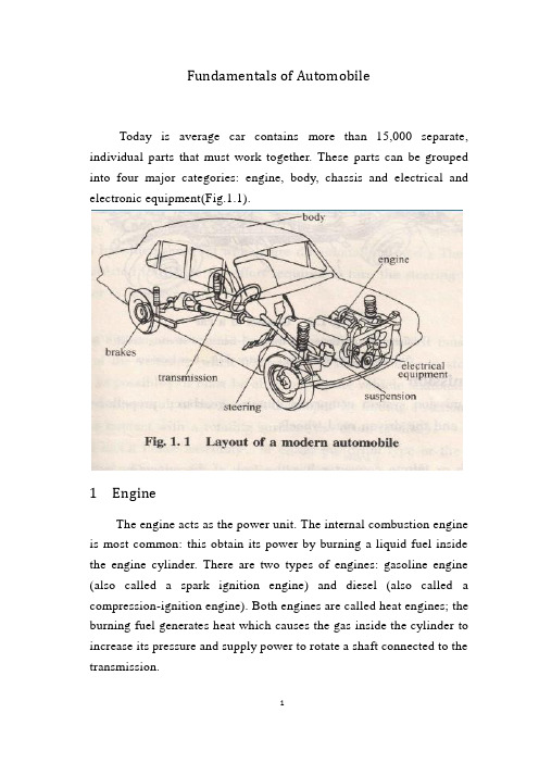
Fundamentals of AutomobileToday is average car contains more than 15,000 separate, individual parts that must work together. These parts can be grouped into four major categories: engine, body, chassis and electrical and electronic equipment(Fig.1.1).1 EngineThe engine acts as the power unit. The internal combustion engine is most common: this obtain its power by burning a liquid fuel inside the engine cylinder. There are two types of engines: gasoline engine (also called a spark ignition engine) and diesel (also called a compression-ignition engine). Both engines are called heat engines; the burning fuel generates heat which causes the gas inside the cylinder to increase its pressure and supply power to rotate a shaft connected to the transmission.2 BodyAn automobile body is a sheet metal shell with windows, doors, a hood, and a trunk deck built into it. It provides a protective covering for the engine, passengers, and cargo. The body is designed to keep passengers safe and comfortable. The body styling provides an attractive, colorful, modern appearance for the vehicle.3 chassisThe chassis is an assembly of those systems that are the major operating parts of a vehicle. The Chassis includes the transmission, suspension, steering, and brake system.3.1 TransmissionThe transmission system comprises clutch, gearbox, propeller shaft, rear axle and differential and the driven road wheels.ClutchThe clutch or torque converter has the task of disconnecting and connecting the engine's power from and to the driving wheels of the vehicle. This action may be manual or automatic.GearboxThe main purpose of the gearbox is to provide a selection of gear ratios between the engine and driving wheels, so that the vehicle can operate satisfactorily under all driving conditions. Gear selection may be done manually by the driver or automatically by a hydraulic control system.Propellor shaftThe function of the propeller (drive) shaft is to transmit the drivefrom the gearbox to the input shaft of the rear axle and differential assembly. Flexible joints allow the rear axle and wheels to move up and down without affecting operation.The role of the drive shaft from the transmission the driving force transmitted to the rear axle input shaft and the differential assembly. Universal joint allows the rear axle and wheels move up and down without affecting operation.Rear axle and differentialThe rear axle and differential unit transmits the engine's rotational power through 90 from propshaft to axle shaft to axle shaft to road wheels. A further function is to allow each driven wheel to turn at a different speed; essential when cornering because the outer wheel must turn further than the inside wheel. A third function is to introduce another gear ratio for torque multiplication.3.2 SuspensionThe axles and wheels are isolated from the chassis by a suspension system . The basic job of the suspension system is to absorb the shocks caused by irregular road surfaces that would otherwise be transmitted to the vehicle and its occupants, thus helping to keep the vehicle on a controlled and level course, regardless of road conditions.3.3 SteeringThe steering system, under the control of the driver at the steering wheel, provides the means by which the front wheels are directionally turned. The steering system may be power assisted to reduce the effort required to turn the steering wheel and make the vehicle easier to manoeuvre.3.4 BrakesThe braking system on a vehicle has three main functions. It must be able to reduce the speed of the vehicle, when necessary; it must be able to stop the car in as short a distance as possible; it must be able to hold the vehicle stationary. The braking action is achieved as a result of the friction developed by forcing a stationary surface(the brake lining)into contact with a rotating surface(the drum or disc).Each wheel has a brake assembly of either the drum type or the disc type, hydraulically operated when the driver applies the foot brake pedal.4 Electrical Equipment and InstrumentationThe electrical system supplies electricity for the ignition, horn, lights, heater, and starter. The electricity level is maintained by a charging circuit. This circuit consists of a battery, and an alternator (or generator). The battery stores electricity. The alternator changes the engine's mechanical energy into electrical energy and recharges the battery.The motor vehicle incorporates a number of electrical devices that are used for:Battery charging –alternator and regulator.Engine purposes –starting and ignition.Safety and convenience –lighting, horn, wipers, washers etc.Driver information –instrumentation and warning lamps.Of these devices instrumentation is, perhaps, most influenced by the advance of microelectronics. The basic electromechanical systems of:Speedometer –for indicating vehicle speed.Engine oil pressure –warning lamp or gauge to show operating limits.Engine coolant temperature –warning lamp or gauge to show operating limits.Battery charging –warning lamp or gauge to indicate satisfactory/unsatisfactory action.Fuel tank content –gauge to show amount of fuel in the fuel tank.are giving way to computerized vehicle management information centres.The Steering System1 The Steering GearThe steering gear mechanism enables the driver to turn the front wheels of the car. The mechanism consists of a steering gear box, pitman arm, drag link, tie rods, steering arms, and steering knuckles, the latter supporting the front wheels(Fig.6.1).Turning the steering wheel turns the steering shaft to which a worm gear is attached within the steering gear box. The steering worm moves a roller through a part of an arc, the motion of which is transmitted to the pitman arm, which moves back and forth across the width of the frame. Several arrangements of rods and levers are in common use but, in general, a drag link, connected to the pitmen arm, transmits the movement to tie rods which are connected to the steering arms. Sideward movement of the steering arms turns the steering knuckles, and the wheels, as they are pivoted on front end support mechanism.There are two types of steering system: manual steering system and power steering system. In the manual type, the driver does all the work of turning the steering wheel, steering gears, wheels, and tires. In the power type, hydraulic fluid assists the operation so that the driver's effort is reduced.Mechanical steering system: And changes the transmission systemby the diverter to be composed.Diverter: By the steering wheel, the steering wheel steering axle, changes meshing to pay (diverter) to be composed.Steering transmission system: By drop arm (drop arm), drag link, drag link arm, about trapezoidal arm, steering knuckle tie rod, if a dry bulb joint composes.Power steering system: Changes the augmenter constitution by mechanical steering system Canada.A typical power steering system needs a power steering pump and reservoir in addition to the steering gear(Fig.6.2). These parts store the hydraulic fluid and provide the hydraulic pressure to assist steering. In most instances, a V-belt from the engine power the hydraulic pump. Hoses lead from the pump to the steering gear and back to the pump.In steering gear box the gear is slightly larger and has other parts. The wormshaft is the same in both systems. Instead of a ball nut, though, the power steering system uses a power piston or rack piston in steering gear box. The power piston has teeth on one side that meshwith the sector teeth. The forward and backward motion of the power piston moves the sector, pitman shaft, and steering linkage.The power steering gear also uses a control valve to send hydraulic fluid into the steering gear at the right time. When the steering wheel starts to move in either direction, the valve opens its ports to sent fluid under pressure into the main chamber of the steering gear. The fluid pushes against the power piston and assists the motion of the steering wheel.Fig.6.2 In an integral power steering system, the power and control are in the same housing as the steering gear2 Front-GeometryThe front wheels are arranged at various angles to the car frame to provide good steering control and stability. The angles are discussed in the following order: caster, camber, steering axis inclination, toe, and turning radius.Caster is the slant of the kingpin forward at the bottom(Fig.6.3). (NOTE: Modern passenger car does not use a kingpin in an independently mounted front wheel suspension, but reference to its former position helps to clarify some front end concepts. The positionof the kingpin would be on a direct line drawn between the two ball joints). The front wheels, when provided with the proper amount of caster, will align themselves in the direction in which the car is moving. Too much caster will cause hard steering and shimmy at low speed. Too little caster will cause wander or weave at high speed and erratic steering when applying the brakes.Camber is the angle between a vertical line and a line drawn through the center of the wheel(Fig.6.4). The top of the wheel is inclined away from the car. The purpose of camber is to place the center of the tire directly under the extended line of the kingpin for easier steering. This places the weight of the car directly over the pivot point.Steering Axis Inclination is the outward tilt of the bottom of the kingpin toward the wheel(Fig.6.5). Modern engineering practice is to minimize camber in order to reduce uneven tire wear, and increase theFig.6.3 Caster Fig.6.4 Camber angular inclination of the kingpin to place its centerline directly under the center of the tire for ease in steering.Steering axis inclination also provides steering stability by raisingthe entire front end of the vehicle during a turn. Gravity causes the spindle ends to tend to return to their straight ahead position. This force is not enough to cause steering, but is enough to provide excellent directional stability. Steering axis inclination is probably a more important steering stability factor than caster.Toe-in is the difference in distance between the front and rear of the front tires, measured at spindle height(Fig.6.6). That is, the wheels are aimed slightly in as if to cross each other, it seems to cross each other's path. Due to compression of the steering linkage parts, the front wheels tend to turn out or away from each other. To offset this, they are provided with a small amount of toe-in. In operation, the wheels travel parallel paths and no side scuffing occurs.Fig.6.5 Steering axis inclinationTurning Radius, or toe-out on turns, is needed when turning a corner. Because the outside wheel on a curve turn about a longer arcthan does the inside wheel, it is necessary to have the inside wheel turn at a sharper angle to prevent tire scuffing and wear. To obtain this action, the steering arms are set at an angle to the wheels. Although the tie rod moves each arm an equal distance, the angular movement is unequal and the wheels toe-out. The sharper the turning angle, the more toe-out results.Fig.6.6 Toe-in汽车部件目前大多数的汽车由超过15000个各自独立的零部件组成,这些零部件必须一起配合工作。
汽车转向系统中英文外文翻译

中英文对照资料外文翻译文献Spin control for carsStability control systems are the latest in a string of technologies focusing on improved diriving safety. Such systems detect the initial phases of a skid and restore directional control in 40 milliseconds, seven times faster than the reaction time of the average human. They correct vehicle paths by adjusting engine torque or applying the left- or-right-side brakes, or both, as needed. The technology has already been applied to the Mercedes-Benz S600 coupe.Automatic stability systems can detect the onset of a skid and bring a fishtailing vehicle back on course even before its driver can react.Safety glass, seat belts, crumple zones, air bags, antilock brakes, traction control, and now stability control. The continuing progression of safety systems for cars has yielded yet another device designed to keep occupants from injury. Stability control systems help drivers recover from uncontrolled skids in curves, thus avoiding spinouts and accidents.Using computers and an array of sensors, a stability control system detects the onset of a skid and restores directional control more quickly than a human driver can. Every microsecond, the system takes a "snapshot," calculating whether a car is going exactly in the direction it is being steered. If there is the slightest difference between where the driver is steering and where the vehicle is going, the system corrects its path in a split-second by adjusting engine torque and/or applying the cat's left- or right-side brakes as needed. Typical reaction time is 40 milliseconds - seven times faster than that of the average human.A stability control system senses the driver's desired motion from the steering angle, the accelerator pedal position, and the brake pressure while determining the vehicle's actual motion from the yaw rate (vehicle rotation about its vertical axis) and lateral acceleration, explained Anton van Zanten, project leader of the Robert Bosch engineering team. Van Zanten's group and a team of engineers from Mercedes-Benz, led by project manager Armin Muller, developed the first fully effective stability control system, which regulates engine torque and wheel brake pressures using traction control components to minimize the difference between the desired and actual motion.Automotive safety experts believe that stability control systems will reduce the number of accidents, or at least the severity of damage. Safety statistics say that most of the deadly accidents in which a single car spins out (accounting for four percent of all deadly collisions) could be avoided using the new technology. The additional cost of the new systems are on the order of the increasingly popular antilock brake/traction control units now available for cars.The debut of stability control technology took place in Europe on the Mercedes-Benz S600 coupe this spring. Developed jointly during the past few years by Robert Bosch GmbH and Mercedes-Benz AG, both of Stuttgart, Germany, Vehicle Dynamics Control (VDC). in Bosch terminology, or the Electronic Stability Program (ESP), as Mercedes calls it, maintains vehicle stability in most driving situations. Bosch developed the system, and Mercedes-Benz integrated it into the vehicle. Mercedes engineers used the state-of-the-art Daimler-Benz virtual-reality driving simulator in Berlin to evaluate the system under extreme conditions, such as strong crosswinds. They then put the system through its paces on the slick ice of Lake Hornavan near Arjeplog, Sweden. Work is currently under way to adapt the technology to buses and large trucks, to avoid jack-knifing, for example.Stability control systems will first appear in mid-1995 on some European S-Class models and will reach the U.S. market during the 1996 model year (November 1995 introduction). It will be available as a $750 option on Mercedes models with V8 engines, and the following year it will be a $2400 option on six-cylinder 鉣俕嶏핤딿냷 $1650 of the latter price is for the traction control system, a prerequisite for stability control.Bosch is not alone in developing such a safety system. ITT Automotive of Auburn Hills, Mich., introduced its Automotive Stability Management System (ASMS) in January at the 1995 North American International Auto Show in Detroit. "ASMS is a quantum leap in the evolution of antilock brake systems, combining the best attributes of ABS and traction control into a total vehicle dynamics management system," said Timothy D. Leuliette, ITT Automotive's president and chief executive officer."ASMS monitors what the vehicle controls indicate should be happening, compares that to what is actually happening, then works to compensate for the difference," said Johannes Graber, ASMS program manager at ITT Automotive Europe. ITT's system should begin appearing on vehicles worldwide near the end of the decade, according to Tom Mathues, director of engineering of Brake & Chassis Systems at ITT Automotive North America. Company engineers are now adapting the system to specific car models from six original equipment manufacturers.A less-sophisticated and less-effective Bosch stability control system already appears on the 1995 750iL and 850Ci V-12 models from Munich-based BMW AG. The BMW Dynamic Stability Control (DSC) system uses the same wheel-speed sensors as traction control and standard anti-lock brake (ABS) systems to recognize conditions that can destabilize a vehicle in curves and corners. To detect such potentially dangerous cornering situations, DSC measures differences in rotational speed between the two front wheels. The DSC system also adds a sensor for steering angle, Utilizes an existing one for vehicle velocity, and introduces its own software control elements in the over allantilock-brake/traction-control/stability-control system.The new Bosch and ITT Automotive stability control systems benefit from advanced technology developed for the aerospace industry. Just as in a supersonic fighter, the automotive stability control units use a sensor-based computer system to mediate between the human controller and the environment - in this case, the interface between tire and road. In addition, the system is built around a gyroscopelike sensor design used for missile guidance.BEYOND ABS AND TRACTION CONTROLStability control is the logical extension of ABS and traction control, according to a Society of Automotive Engineers paper written by van Zanten and Bosch colleagues Rainer Erhardt and Georg Pfaff. Whereas ABS intervenes when wheel lock is imminent during braking, and tractioncontrol prevents wheel slippage when accelerating, stability control operates independently of the driver's actions even when the car is free-rolling. Depending on the particular driving situation, the system may activate an individual wheel brake or any combination of the four and adjust engine torque, stabilizing the car and severely reducing the danger of an uncontrolled skid. The new systems control the motion not only during full braking but also during partial braking, coasting, acceleration, and engine drag on the driven wheels, circumstances well beyond what ABS and traction control can handle.The idea behind the three active safety systems is the same: One wheel locking or slipping significantly decreases directional stability or makes steering a vehicle more difficult. If a car must brake on a low-friction surface, locking its wheels should be avoided to maintain stability and steerability.Whereas ABS and traction control prevent undesired longitudinal slip, stability control reduces loss of lateral stability. If the lateral forces of a moving vehicle are no longer adequate at one or more wheels, the vehicle may lose stability, particularly in curves. What the driveɲ逾半쀹ᾩ쏪 ﲢ끣 "fishtailing" is primarily a turning or spinning around the vehicle's axis. A separate sensor must recognize this spinning, because unlike ABS and traction control, a car's lateral movement cannot be calculated from its wheel speeds.SPIN HANDLERSThe new systems measure any tendency toward understeer (when a car responds slowly to steering changes), or over-steer (when the rear wheels try to swing around). If a car understeers and swerves off course when driven in a curve, the stability control system will correct the error by braking the inner (with respect to the curve) rear wheel. This enables the driver, as in the case of ABS, to approach the locking limit of the road-tire interface without losing control of the vehicle. The stability control system may reduce the vehicle's drive momentum by throttling back the engine and/or by braking on individual wheels. Conversely, if the hteral stabilizing force on the rear axle is insufficient, the danger of oversteering may result in rear-end breakaway or spin-out. Here, the system acts as a stabilizer by applying the outer-front wheel brake.The influence of side slip angle on maneuverability, the Bosch researchers explained, shows that the sensitivity of the yaw moment on the vehicle, with respect to changes in the steeringangle, decreases rapidly as the slip angle of the vehicle increases. Once the slip angle grows beyond a certain limit, the driver has a much harder time recovering by steering. On dry surfaces, maneuverability is lost at slip-angle values larger than approximately 10 degrees, and on packed snow at approximately 4 degrees.Most drivers have little experience recovering from skids. They aren't aware of the coefficient of friction between the tires and the road and have no idea of their vehicle's lateral stability margin. When the limit of adhesion is reached, the driver is usually caught by surprise and very often reacts in the wrong way, steering too much. Oversteering, ITT's Graber explained, causes the car to fishtail, throwing the vehicle even further out of control. ASMS sensors, he said, can quickly detect the beginning of a skid and momentarily activate the brakes at individual wheels to help return the vehicle to a stable line.It is important that stability control systems be user-friendly at the limit of adhesion - that is, to act predictably in a way similar to normal driving.The biggest advantage of stability control is its speed - it can respond immediately not only to skids but also to shifting vehicle conditions (such as changes in weight or tire wear) and road quality. Thus, the systems achieve optimum driving stability by changing the lateral stabilizing forces.For a stability control system to recognize the difference between what the driver wants (desired course) and the actual movement of the vehicle (actual course), current cars require an efficient set of sensors and a greater computer capacity for processing information.The Bosch VDC/ESP electronic control unit contains a conventional circuit board with two partly redundant microcontrollers using 48 kilobytes of ROM each. The 48-kB memory capacity is representative of the large amount of "intelligence" required to perform the design task, van Zanten said. ABS alone, he wrote in the SAE paper, would require one-quarter of this capacity, while ABS and traction control together require only one half of this software capacity.In addition to ABS and traction control systems and related sensors, VDC/ESP uses sensors for yaw rate, lateral acceleration, steering angle, and braking pressure as well as information on whether the car is accelerating, freely rolling, or braking. It obtains the necessary information on the current load condition of the engine from the engine controller. The steering-wheel anglesensor is based on a set of LED and photodiodes mounted in the steering wheel. A silicon-micromachine pressure sensor indicates the master cylinder's braking pressure by measuring the brake fluid pressure in the brake circuit of the front wheels (and, therefore, the brake pressure induced by the driver).Determining the actual course of the vehicle is a more complicated task. Wheel speed signals, which are provided for antilock brakes/traction control by inductive wheel speed sensors, are required to derive longitudinal slip. For an exact analysis of possible movement, however, variables describing lateral motion are needed, so the system must be expanded with two additional sensors - yaw rate sensors and lateral acceleration sensors.A lateral accelerometer monitors the forces occurring in curves. This analog sensor operates according to a damped spring-mass mechanism, by which a linear Hall generator transforms the spring displacement into an electrical signal. The sensor must be very sensitive, with an operating range of plus or minus 1.4 g.YAW RATE GYROAt the heart of the latest stability control system type is the yaw rate sensor, which is similar in function to a gyroscope. The sensor measures the speed at which the car rotates about its vertical axis. This measuring principle originated in the aviation industry and was further developed by Bosch for large-scale vehicle production. The existing gyro market offers two widely different categories of devices: $6000 units for aerospace and navigation systems (supplied by firms such as GEC Marconi Avionics Ltd., of Rochester, Kent, U.K.) and $160 units for videocameras. Bosch chose a vibrating cylinder design that provides the highest performance at the lowest cost, according to the SAE paper. A large investment was necessary to develop this sensor so that it could withstand the extreme environmental conditions of automotive use. At the same time, the cost for the yaw rate sensor had to be reduced so that it would be sufficiently affordable for vehicle use.The yaw rate sensor has a complex internal structure centered around a small hollow steel cylinder that serves as the measuring element. The thin wall of the cylinder is excited with piezoelectric elements that vibrate at a frequency of 15 kilohertz. Four pairs of these piezo elements are arranged on the circumference of the cylinder, with paired elements positionedopposite each other. One of these pairs brings the open cylinder into resonance vibration by applying a sinusoidal voltage at its natural frequency to the transducers; another pair, which is displaced by 90 degrees, stabilizes the vibration. At both element pairs in between, so-called vibration nodes shift slightly depending on the rotation of the car about its vertical axis. If there is no yaw input, the vibration forms a standing wave. With a rate input, the positions of the nodes and antinodes move around the cylinder wall in the opposite direction to the direction of rotation (Coriolis acceleration). This slight shift serves as a measure for the yaw rate (angular velocity) of the car.Several drivers who have had hands-on experience with the new systems in slippery cornering conditions speak of their cars being suddenly nudged back onto the right track just before it seems that their back ends might break away.Some observers warn that stability controls might lure some drivers into overconfidence in low-friction driving situations, though they are in the minority. It may, however, be necessary to instruct drivers as to how to use the new capability properly. Recall that drivers had to learn not to "pump" antilock brake systems.Although little detail has been reported regarding next-generation active safety systems for future cars (beyond various types of costly radar proximity scanners and other similar systems), it is clear that accident-avoidance is the theme for automotive safety engineers. "The most survivable accident is the one that never happens," said ITT's Graber. "Stability control technology dovetails nicely with the tremendous strides that have been made to the physical structure and overall capabilities of the automobile." The next such safety system is expected to do the same.汽车的转向控制控制系统稳定性是针对提高驾驶安全性提出的一系列措施中最新的一个。
- 1、下载文档前请自行甄别文档内容的完整性,平台不提供额外的编辑、内容补充、找答案等附加服务。
- 2、"仅部分预览"的文档,不可在线预览部分如存在完整性等问题,可反馈申请退款(可完整预览的文档不适用该条件!)。
- 3、如文档侵犯您的权益,请联系客服反馈,我们会尽快为您处理(人工客服工作时间:9:00-18:30)。
Auto steering systemAbstract: With the rapid development of electronic technology, people on the vehicle steering control performance of more and more high. Wire control steering system will be the trend of the development of automobile steering system. Normally according to mechanical steering gear form can be divided into: super-modulus gear type, circulation ball type, worm wheel type, worm gear and worm refers to pin type. The increase of vehicle weight and people to the improvement of vehicle handling performance requirements, simple mechanical steering system can not meet needs, power steering system came into being, it can in the pilot turned the steering wheel and at the same time provide power, power steering system is divided into hydraulic steering system and electric steering system 2 kinds. Hydraulic steering system which is the most widely used steering system.Hydraulic steering system is the basis of the mechanical system increases the system, including hydraulic pump, v-shaped belt wheel, oil injection equipment, power devices and control valves. With the help of the automobile engine driving hydraulic pump, air compressor and generator etc, in order to hydraulic, pneumatic or electric power increases the power of the front wheel steering the pilot control to make drivers can light the flexibility to manipulate car turned, reduce labor intensity, improve the driving safety.Electric power steering system is now the development direction of car steering system, its working principle is: EPS system to the ECU from steering wheel torque sensor and speed sensor signal analysis, control motor to produce the proper power torque, assist drivers finish to the operation.Key words: Wire control steering system Hydraulic steering system Electric power steering system sensorAlong with automobile electronic technology swift and violent development, the people also day by day enhance to the motor turning handling quality request. The motor turning system changed, the hydraulic pressure boost from the traditional machinery changes (Hydraulic Power Steering, is called HPS), the electrically controlled hydraulicpressure boost changes (Elect ric Hydraulic Power Steering, is called EHPS), develops the electrically operated boost steering system (Elect ric Power Steering, is called EPS), finally also will transit to the line controls the steering system (Steer By Wire, will be called SBW).The machinery steering system is refers by pilot's physical strength achievement changes the energy, in which all power transmission all is mechanical, the automobile changes the movement is operates the steering wheel by the pilot, transmits through the diverter and a series of members changes the wheel to realize. The mechanical steering system by changes the control mechanism, the diverter and major part changes the gearing 3 to be composed.Usually may divide into according to the mechanical diverter form: The gear rack type, follows round the world -like, the worm bearing adjuster hoop type, the worm bearing adjuster refers sells the type. Is the gear rack type and follows using the broadest two kinds round the world -like (uses in needing time big steering force).In follows round the world -like in the diverter, the input changes the circle and the output steering arm pivot angle is proportional; In the gear rack type diverter, the input changes the turn and the output rack displacement is proportional. Follows round the world -like the diverter because is the rolling friction form, thus the transmission efficiency is very high, the ease of operation also the service life are long, moreover bearing capacity, therefore widely applies on the truck. The gear rack type diverter with follows round the world -like compares, the most major characteristic is the rigidity is big, the structure compact weight is light, also the cost is low. Because this way passes on easily by the wheel the reacting force to the steering wheel, therefore has to the pavement behavior response keen merit, but simultaneously also easy to have phenomena and so on goon and oscillation, also its load bearing efficiency relative weak, therefore mainly applies on the compact car and the pickup truck, at present the majority of low end passenger vehicle uses is the gear rack type machinery steering system.Along with the vehicles carrying capacity increase as well as the people to the vehicles handling quality request enhancement, the simple mechanical type steering systemwere already unable to meet the needs, the power steering system arise at the historic moment, it could rotate the steering wheel while the pilot to provide the boost, the power steering system divides into the hydraulic pressure steering system and the electrically operated steering system two kinds.Hydraulic pressure steering system is at present uses the most widespread steering system.The hydraulic pressure steering system increased the hydraulic system in the mechanical system foundation, including hydraulic pump, V shape band pulley, drill tubing, feed installment, boost installment and control valve. It with the aid of in the motor car engine power actuation hydraulic pump, the air compressor and the generator and so on, by the fluid strength, the physical strength or the electric power increases the pilot to operate the strength which the front wheel changes, enables the pilot to be possible nimbly to operate motor turning facilely, reduced the labor intensity, enhanced the travel security.The hydraulic pressure boost steering system from invented already had about half century history to the present, might say was one kind of more perfect system, because its work reliable, the technology mature still widely is applied until now. It takes the power supply by the hydraulic pump, after oil pipe-line control valves to power hydraulic cylinder feed, through the connecting rod impetus rotation gear movement, may changes the boost through the change cylinder bore and the flowing tubing head pressure size the size, from this achieved changes the boost the function. The traditional hydraulic pressure type power steering system may divide into generally according to the liquid flow form: Ordinary flow type and atmospheric pressure type 2 kind of types, also may divide into according to the control valve form transfers the valve type and the slide-valve type.Along with hydraulic pressure power steering system on automobile daily popularization, the people to operates when the portability and the road feeling request also day by day enhance, however the hydraulic pressure power steering system has many shortcomings actually: ①Because its itself structure had decided it is unable to guarantee vehicles rotates the steering wheel when any operating mode, all has the ideal operation stability, namely is unable simultaneously to guarantee time the low speed changes the portability and the high speed time operation stability; ②The automobile changes thecharacteristic to drive the pilot technical the influence to be serious; ③The steering ratio is fixed, causes the motor turning response characteristic along with changes and so on vehicle speed, transverse acceleration to change, the pilot must aim at the motor turning characteristic peak-to-peak value and the phase change ahead of time carries on certain operation compensation, thus controls the automobile according to its wish travel. Like this increased pilot's operation burden, also causes in the motor turning travel not to have the security hidden danger; But hereafter appeared the electrically controlled hydraulic booster system, it increases the velocity generator in the traditional hydraulic pressure power steering system foundation, enables the automobile along with the vehicle speed change automatic control force size, has to a certain extent relaxed the traditional hydraulic pressure steering system existence question.At present our country produces on the commercial vehicle and the passenger vehicle uses mostly is the electrically controlled hydraulic pressure boost steering system, it is quite mature and the application widespread steering system. Although the electrically controlled hydraulic servo alleviated the traditional hydraulic pressure from certain degree to change between the portability and the road feeling contradiction, however it did not have fundamentally to solve the HPS system existence insufficiency, along with automobile microelectronic technology development, automobile fuel oil energy conservation request as well as global initiative environmental protection, it in aspect and so on arrangement, installment, leak-proof quality, control sensitivity, energy consumption, attrition and noise insufficiencies already more and more obvious, the steering system turned towards the electrically operated boost steering system development.The electrically operated boost steering system is the present motor turning system development direction, its principle of work is: EPS system ECU after comes from the steering wheel torque sensor and the vehicle speed sensor signal carries on analysis processing, controls the electrical machinery to have the suitable boost torque, assists the pilot to complete changes the operation. In the last few years, along with the electronic technology development, reduces EPS the cost to become large scale possibly, Japan sends the car company, Mitsubishi Car company, this field car company, US's Delphi automobilesystem company, TRW Corporation and Germany's ZF Corporation greatly all one after another develops EPS.Mercedes2Benz and Siemens Automotive Two big companies invested 65,000,000 pounds to use in developing EPS, the goal are together load a car to 2002, yearly produce 300 ten thousand sets, became the global EPS manufacturer. So far, the EPS system in the slight passenger vehicle, on the theater box type vehicle obtains the widespread application, and every year by 300 ten thousand speed development.Steering is the term applied to the collection of components, linkages, etc. which allow for a vessel (ship, boat) or vehicle (car) to follow the desired course. An exception is the case of rail transport by which rail tracks combined together with railroad switches provide the steering function.The most conventional steering arrangement is to turn the front wheels using ahand–operated steering wheel which is positioned in front of the driver, via the steering column, which may contain universal joints to allow it to deviate somewhat from a straight line. Other arrangements are sometimes found on different types of vehicles, for example, a tiller or rear–wheel steering. Tracked vehicles such as tanks usually employ differential steering — that is, the tracks are made to move at different speeds or even in opposite directions to bring about a change of course.Many modern cars use rack and pinion steering mechanisms, where the steering wheel turns the pinion gear; the pinion moves the rack, which is a sort of linear gear which meshes with the pinion, from side to side. This motion applies steering torque to the kingpins of the steered wheels via tie rods and a short lever arm called the steering arm.Older designs often use the recirculating ball mechanism, which is still found on trucks and utility vehicles. This is a variation on the older worm and sector design; the steering column turns a large screw (the "worm gear") which meshes with a sector of a gear, causing it to rotate about its axis as the worm gear is turned; an arm attached to the axis of the sector moves the pitman arm, which is connected to the steering linkage and thus steers the wheels. The recalculating ball version of this apparatus reduces the considerable friction by placing large ball bearings between the teeth of the worm and those of the screw; at either end of the apparatus the balls exit from between the two piecesinto a channel internal to the box which connects them with the other end of the apparatus, thus they are "recirculated".The rack and pinion design has the advantages of a large degree of feedback and direct steering "feel"; it also does not normally have any backlash, or slack. A disadvantage is that it is not adjustable, so that when it does wear and develop lash, the only cure is replacement.The recirculating ball mechanism has the advantage of a much greater mechanical advantage, so that it was found on larger, heavier vehicles while the rack and pinion was originally limited to smaller and lighter ones; due to the almost universal adoption of power steering, however, this is no longer an important advantage, leading to the increasing use of rack and pinion on newer cars. The recirculating ball design also has a perceptible lash, or "dead spot" on center, where a minute turn of the steering wheel in either direction does not move the steering apparatus; this is easily adjustable via a screw on the end of the steering box to account for wear, but it cannot be entirely eliminated or the mechanism begins to wear very rapidly. This design is still in use in trucks and other large vehicles, where rapidity of steering and direct feel are less important than robustness, maintainability, and mechanical advantage. The much smaller degree of feedback with this design can also sometimes be an advantage; drivers of vehicles with rack and pinion steering can have their thumbs broken when a front wheel hits a bump, causing the steering wheel to kick to one side suddenly (leading to driving instructors telling students to keep their thumbs on the front of the steering wheel, rather than wrapping around the inside of the rim). This effect is even stronger with a heavy vehicle like a truck; recirculating ball steering prevents this degree of feedback, just as it prevents desirable feedback under normal circumstances.The steering linkage connecting the steering box and the wheels usually conforms to a variation of Ackermann steering geometry, to account for the fact that in a turn, the inner wheel is actually traveling a path of smaller radius than the outer wheel, so that the degree of toe suitable for driving in a straight path is not suitable for turns.As vehicles have become heavier and switched to front wheel drive, the effort to turn the steering wheel manually has increased - often to the point where major physical exertion is required. To alleviate this, auto makers have developed power steering systems. There are two types of power steering systems—hydraulic and electric/electronic. There is also a hydraulic-electric hybrid system possible.A hydraulic power steering (HPS) uses hydraulic pressure supplied by anengine-driven pump to assist the motion of turning the steering wheel. Electric power steering (EPS) is more efficient than the hydraulic power steering, since the electric power steering motor only needs to provide assist when the steering wheel is turned, whereas the hydraulic pump must run constantly. In EPS the assist level is easily tunable to the vehicle type, road speed, and even driver preference. An added benefit is the elimination of environmental hazard posed by leakage and disposal of hydraulic power steering fluid.An outgrowth of power steering is speed adjustable steering, where the steering is heavily assisted at low speed and lightly assisted at high speed. The auto makers perceive that motorists might need to make large steering inputs while manoeuvering for parking, but not while traveling at high speed. The first vehicle with this feature was the Citroën SM with its Diravi layout, although rather than altering the amount of assistance as in modern power steering systems, it altered the pressure on a centring cam which made the steering wheel try to "spring" back to the straight-ahead position. Modern speed-adjustable power steering systems reduce the pressure fed to the ram as the speed increases, giving a more direct feel. This feature is gradually becoming commonplace across all new vehicles.汽车转向系统摘要:随着汽车电子技术的快速发展,人们对汽车转向的操纵性能越来越高。