中英文文献翻译-电动助力转向系统
EPS电动助力转向文献综述

电动转向助力的原理、分类及发展综述摘要:转向系统作为汽车的一个重要组成部分,其性能的好坏将直接影响到汽车的转向特性、稳定性和行驶安全性。
在国外,各大汽车公司对汽车电动助力转向系统(Electric power steering-EPS,或称Elec-tric Assisted Steering-EAS)的研究有20多年的历史。
为了解决转向系统“轻”与“灵”的矛盾[1],采用现代控制技术和电子技术的电动助力转向系统(EPS)应运而生。
随着近年来电子控制技术的成熟和成本的降低,EPS越来越受到人们的重视,并以其具有传统动力转向系统不可比拟的优点,迅速迈向了应用领域,部分取代了传统液压动力转向系统(Hydraulic powersteering,简称HPS)。
关键词:工作原理、分类、发展1.EPS的工作原理及特点电动助力转向系统是在传统机械转向系统的基础上发展起来的。
它利用电动机产生的动力来帮助驾驶员进行转向操作,系统主要由三大部分构成,信号传感装置(包括扭矩传感器、转角传感器和车速传感器),转向助力机构(电机、离合器、减速传动机构)及电子控制装置[2]。
电动机仅在需要助力时工作,驾驶员在操纵转向盘时,扭矩转角传感器根据输入扭矩和转向角的大小产生相应的电压信号,车速传感器检测到车速信号,控制单元根据电压和车速的信号,给出指令控制电动机运转,从而产生所需要的转向助力。
其结构示意图如图1所示。
图1 带双小齿轮的电动机机械转向助力器总体视图1.1EPS的优点1.1.1节约了能源消耗。
没有转向油泵,且电动机只是在需要转向时才接通电源,所以动力消耗和燃油消耗均可降到最低。
1.1.2对环境无污染。
该系统应用电力作为能源,消除了由于转向油泵带来的噪声污染。
也不存在液压助力转向系统中液压油的泄漏与更换而造成的污染。
同时该系统由于没有使用不可回收的聚合物组成的油管、油泵和密封件等配件,从而避免了污染。
1.1.3增强了转向跟随性。
汽车转向系统中文文献

DSP-based电力辅助转向使用无刷直流电机MURUGAN NANDAKUMAR R,S和M S MOHIYADEENBharat Electronics Limited, Nandambakkam, Chennai 600 089e-mail: muruganr@bel.co.in; nandakumars@bel.co.in;mohiyadeenms@bel.co.in本文介绍了电的设计方法和步骤辅助动力转向系统(简称EAS)用无刷直流电机为一辆汽车。
控制建筑由两层控制,即车辆速度相关的控制以及扭矩协助控制。
在更高的层次上控制系统的体系结构、功能的车辆作为援助速度控制器、液位控制器的控制力。
在较低的水平,给出了转矩控制器的努力水平的控制。
这已经是实现了由扭矩传感器和车辆在DSP这种传感器。
为实现在系统中,DSP-based三相逆变器直流无刷电动机控制器模块是特意使用采用霍尔传感器反馈和一个单一的dc-link电流传感器。
这项工作是实现光商用车拥有一个循环球式齿轮。
这是第一次(简称EAS)的实施为这种类型的车辆在任何地方在世界上。
一般来说,有离合器递归断开电动机在高速度或非正常条件下从齿轮箱。
在该实现电动机直接耦合到变速箱没有离合器和所有的人异常处理的处理器。
这是执行,不修改车辆供应系统,比如改变现有的交流发电机或额定值电池,利用现有的传感器。
设计是这样一种方式的那种感觉司机援助可以变换轻易地在任何时间。
控制的性能实验结果表明,系统是它被测试在其中的轻型商用车辆(LCV)。
关键词。
无刷直流电机;EAS;转向系统。
1.介绍动力转向系统的转向努力降低车辆的使用外部的源,来协助将轮子。
现在大多数新一代车辆动力转向,由于车辆的趋势,走向更大质量和更宽的轮胎,所有增加的控制力所需要的。
现代交通工具很难动作,速度较低(例如当停车场)如果没有人帮助。
大多数助力转向系统工作,用皮带驱动泵提供的液压系统。
该液压压力泵,是所产生的车辆的引擎驱动。
中英文文献翻译—转向器的简单介绍
中英文文献翻译—转向器的简单介绍附录Hyundai Motor on the stcering control of the request is lightweight,safe,reliable,and should have sufficient life. In order to meet these requirements,the design of the steering gear should have a reasonable transmission ratio characteristics,the correct gap cating together,a higher transmission efficiency,sufficient rigidiy and strength.If the steering gear in the design is reasonable,then the product is good and bad parts of the key issucs of manufacturing and assembly.How to control the quality of the product?The key problem is that a reasonable detection methods,the key to strictly control the passing rate of time,such products will be able to guarantee the quality of parts and components.First of all,the quality of shifting ASSY,should control the assenmbly and to ensure that turning the steering shaft torque and rotational axis and the transmission gap between components.Followed by testing the performance of steering gear,steering gear must also be adopted by all types of test-bed to verify the established angle transmission ratio,transmission efficiency,rotational torque,rigid.In addition to examination other than the above-mentioned steering performance,but also in the pilot stage of its life nuclear reliability and life expectancy that is static torsion test:a thin red hammer,hit test,fatigue life test.To determine whether the quality of the product in hand national standards.Noise from the steering angle repair cream,which is also a test method to detect and can learn from the J class machincry manufacturing industry in China “in the past only means to recognize the importance of detection,and the lack of”lack of testing and testing of the poorlaw awareness.So have some of the parts is a qualified products I materials,and assembly of products from the pilot test proved to be defective,or:The test can verify the quality of products and design for the steering gear (1) the accuracy of parts of the foot only, finish second,two-phase the location of the elite“Measuring the content of L steering shaf t loaded journal bearings.Department feet inch accuracy and smoothness,anti-worm or worm-inch accuracy.smoothness and surface hardness and magnetic---for testing;steering vertical axis arm journal dimensional accuracy and smoothness, the worm wheel roller bearing of the journal center hole distance,wheel bearing and the journal” hole angle from the Chinese side,the block size,finish and degree of asymmetry;circulating ball tooth-type radial fan,big-law length,journal hardness,the magnetic;browser to Min Xuan cochlear aperture wheel size precision,smoothness,tooth surface roughness,intermediate thick teech,tooth,tooth degree ofasymmetry; ball rolling circle diameter,smooth,cylindrical roller Road”degree of accuracy and bias,raccway adjacent pitch error,cumulative error section of grass lines and sub-racj section from Rolling Road Center,rack section Road center line and the roll of injustice;carburizing layer thickness,hardn ess’magnetic flaw detection;ahift steering shaft shell aperture,roughness,different degree of heart;shift towards vertical axis aperture arm flying finish,different degree of heart;chaos and stecring shaft steering arm hole down the center distance,steering shaft-hole axes and steering arm hole down the center line of the non-verticality.(2) parts of cleanliness.Detection of the site is turning-browser shell surface and the surface parts.Detection method is to use cleaning fluid to clean parts,and then the cleaning fluid with impurities,and vacuum membranc leaching;further 120 weeks of petrol industrial solvents the menbranc will be washed with inpurities.To be volatile after the membranc cleaning fluid,together with the impurities from weighing with the magne cellophane packets are sorted in the iron impurities said the weight of a scrap-iro, The iron filings and then 40 times on the microscope with a disability in most dogs measured particle size.(3)assembly of the leakage.. Does not allow any leakage of the phenomenon of steering.Because of internal lubricants in the steering gear is used to turn parts lubricated friction pair,and if as a result of damage caused by leakng seals,lubrication will be affected; resulting in increased friction and wear parts and reduce the life span of steering gera;transminssion efficiency at the same time will lower.The use of conventional vibration and temperature 40 under the conditions of inspection,the shell and shell cap shaft oil scal joints as well as whether the spill.,and water to observe whether there are leakages.(4) after a good tune stecring assembly should check the technical requirements flexible and comfortable when turning the steering wheel,there is no axial gap I turn the steering wheel of the total value of the number required to turn around a few cars in line with the original request.Steering gear shife, also known as machine,machine,machine direction.which is steering the most important parts. Its role ie to increase the spread to turn steering wheel and transmission mechanism to change the direction of power transfer.Hydraulic Steering Hydraulic steering vehicles are windelyused in marine hydraulicsteering and rudder.Drivers can be used through its ability to manipulate smaller shift power to achieve greater control and performance of safe,reliable,flexible manipulation,light.The manipulation of steering is hydraulic,that is in the steering column and steering wheel there is no mechanical connection between the steering gear is between the fuel tank and steering hydraulic pipes or hoses link.When turning the steering wheel,steering wheel rotation in accordance with the relative proportion of transport fuel,the fuel tank directly into the corresponding control side,while the other side of the oil back to tank.BZZ steering is a switch-type full-hydraulic steering valve with the following characteristics:the elimination of mechanical linkage device,the host can reduce costs,provide a reliable,lightweight structures,manipulation of a flexible lightweight,safe,reliable,and can be very small continuous torque stepless control of rotation, provided to the control loop,as well as a wide range of host size choice,able to shift and a variety of pumps and hydraulic supply system.Steering by the structure can be divided into many types.History,there have been many forms of steering,there is currently more commonly used rack and pinion,worm means crank pins,recycling the ball-rack fan gear type,recycling the ball crank pins means,such as worm-type wheel.The second,fourth,respectively, is the first,the third form of the deformation,and the worm wheel is even more rare type.If the form in accordance with assistance,but also can be divided into mechanical(no help),and power-style(with help) two types of power steering which can be divided into pressure andmotivation,hydraulic-power, Electric power-type,electro-hydraulic power types of blocks.It is a rack and pinion of steering one of the most common.The basic structure is a pair of mutually meshing rack and pinon.Pinon steering drive shaft rotates, rack linear motion would be done. In some cases,directly driven by the rack cross-bar,you can make of steering wheel shift. So,this is one of the most simple steering. Its advantage is simple structure,low-cost,steering sensitivity,small size,can be directly cross-link.In widely used vehicle.It is a worm for the active parts,crank pin for the steering gear follower.Worm has a trapezoidal thread,referring to a finger-shaped pin with tapered bearings in the crank bearings,the crank shaft and the shift into one arm.Shifted through steering wheel rotating worm,helical worm embedded in the cone-shaped slot means the marketing side of the rotation,the crank shaft and the shift into one arm.Shifted through steering wheel rotating worm,helical worm embedded in the cone-shaped slot means the marketing side of the rotation,the side rocker shaft to do around the shifted are movement,thereby stimulating and steering crank arm swing down and then turning to make shift transmission wheel deflection.This steering is usually used to turn power on a larger truck.Circulating ball-type:This device is turned by the gear mechanism from the steering wheel to slow down the rotation of power,so that the rotation of steering wheel movement into rotary movement of the turbine worm,ball screw and nut holding the ball engagement,which Ball screw linear motion into rotary movement,with the fan-shaoed nut meshing gears,linear motion into rotary movement,with the fan-shaped nut meshing gears,linear motion into rotary movement,with the fan-shapednut meshing gears,linear motion into rotary movement again to shake the rod arm,link arm moving again so that even the bar and cross bar to do a straight-line movement to change the wheels direction.This is a classical institutions,most modern cars no longer have to use,but the way was the latest by the application of power steering device.It is equivalent to the principle use of nuts and bolts in the rotation process of relative movement,and in between the thread and thrend the ball into the folder to reduce the resistance,all the ball,both connected in a closed loop of the spiral curve rolling ball club is named after the cycle.Hydraulic rack and pinion steering gear is relative to the case of rack and pinion steering gear machinery, mainly to increase the steering pump,steering oiler,steering pineline, steering valve,steering components,suan as fuel tanks,with a view to improve the pilot hand,the purpose of increasing power steering of the steering device.After 10 years of internal development,has become a mature R&D and manufacturing technology manufacturers have Yubei Koyo Steering Gear Co.Ltd.and other enterprises.With the rapid development of automobile industry,as well as for comfort,safety and continuous improvement in performance,steering systems are also changing with the advance of technology.For the time being,electric power steering systems is turning the forefront of the industry rescarch projects,in accordance with its distribution of the form of string can be divided into power,gear Power,power rack,power bar,the form of electro-hydraulic power. Ago in some sci-fi movies of the unmanned aircraft can occur,such as unmanned acrial vehicle is now a reality,steering systems are moving in the direction of the development of more advanced,such as rescarch anddevelopment from Japan JTEKT advanced by the steer-by-wire systems.In this paper,choice-bassed recycling the ball GX1608A gear-steering rack as a research topic,its main contents are: knowledge of automotive steering gear,ball-type steering gear cycle of the main paramenters and design choices.Design also includes the shift rocker shaft,involute spline,fan gear shaft and screw shaft design and verification.According to its own independent study completed by the steering shaft and screw shaft rocker design and verification,in other parts of the network,as well as through the school library to collect relevant information and fax to the future,in the papers have used information the mark.The design has been through a total of about 16 Chinese and foreign-related literature,and learn from the relevant parts of which the essence of the final design of the times.Because of its limited ability to learn and,I urge teachers and experts have pointed out that less than one.中文现代汽车对转向器的要求是操纵轻便,安全、可靠、,并应具有足够的使用寿命。
中英文文献翻译-电动助力转向系统

附录A 外文文献Electric Power Steering system1.HistoryIn automobile development course, Steering system experienced four stages of development: from the initial mechanical Steering system (for your DNS setting Steering, abbreviation ) development for Hydraulic Steering system (Hydraulic Power Steering, abbreviation HPS), then again appeared electronically controlled Hydraulic Steering system (Electro Hydraulic Power Steering, abbreviation EHPS) and Electric Power Steering system (Steering, room Power as EPS). Assemble mechanical steering system of car parking and low-speed driving, when the driver's steering control burden too heavy, in order to solve this problem, the American GM in the 1950s took the lead in the car hydraulic steering system. But, hydraulic steering system can't juggle vehicles to speed portability and high speed, so the steering stability Koyo in Japan in 1983, with the company introduced the application of speed sensing function of hydraulic steering system. This new type of steering system can provide speed increased with the decreasing steering, but complicated structure, cost is higher, and cannot overcome hydraulic system itself has many shortcomings, is a cross between a hydraulic steering and electric power steering the transition between the products. In 1988, Japan Suzuki company first in small cars equipped with Cervo Koyo company development on the steering column, power type electric power steering system; In 1990, Japan Honda NSX in sports car company adopted self-developed rack power type electric power steering system, henceforth unveils the electric power steering in cars applications history2.Working principleElectric power steering system are as follows: first, the working principle, torque sensor measured on steering wheel drivers on the manipulation of the moment, the wheel speed sensors detect the vehicle driving speed, then present the two signals to ECU; According to the built-in control strategy: ECU, calculates the ideal target booster torque, into current instructions to motor; Then, the power generated by the torque motor slowdown institutions amplification on steering system in mechanical manipulation of the moment, and the driver together to overcome resistance torque, realize to the vehicle steering.3. Working processElectric power steering system as traditional hydraulic system alternative products has entered into the auto manufacturing. And had predicted instead, EPS not only applicable to small cars, and some for 12V medium vehicle installed electric system.EPS system includes the following components:The torque sensor: detection steering wheel motion and vehicle motion situation;Electronic control units: according to provide the torque sensor the size of the signal computing power;Motor: according to the electronic control units; turn power output value generation Reduction gear: improve motor power, and produce turn it sends to steering mechanism.Other vehicle system control algorithm input information is provided by the car CAN bus (for example steering Angle and bus speed, etc.). Motor drive also need other information, such as motor rotor position and the three-phase motor sensor (current sensor provided). Motor control by four MOSFET, due to micro controller cannot direct drive of large gate capacitance, MOSFET using drive IC form needed the interface, for safety, complete motor control system must implement monitoring, motor control system integration in PCB, usually contains a relay, the relay use, as the main switch under the condition of the fault detection, disconnect motor and electronic control units.Micro control device must control EPS system and have brushless motor. Micro control device according to the torque sensor provide needed the steering wheel torque information, forming a current control loop. In order to improve the security of the system level, the micro control device should have an on-board oscillator, so even in external oscillator malfunction case, also ensure micro control device performance, also should have chip watchdog. Infineon XC886 integration of the company all the important micro control device component, other safety features for through the software to realize, if must implement safety standards IEC61508 industries, you have to finish all kinds of diagnosis and self-inspection task and increase micro control device work load. At present different customers use of torque sensor and rotor position sensor difference is very big. They use different measuring principle, such as decomposing machine, magnetic resonance device, based on the integration of giant magnet or stance sensor.The role of power levels is switch electric current. The power level has two main functions: drive IC control and protection MOSFET, MOSFET itself and to be responsible for switch currents. MOSFET and partition.Micro control device PWM output port provides driver current and voltage is too low, can't directly connected with MOSFET screen realization. Drive IC role is to provide enough current, the grid to charge for MOSFET, so that in the and discharge 20kHz conditions, and ensure the normal realization switch for discretion side provides the high bar source voltage MOSFET, ensure that you get the low conduction resistance. If the high side MOSFET in open state, to source potential close battery level. Want to make MOSFET arrived at nominal conduction resistance, gate to higher than 8V source voltage. MOSFET completely conduction needed the most ideal voltage is required, therefore 10V or above a grid of potential than battery voltage 10V is higher. Charge pump is to ensure that the function to the largest extent reduce MOSFET power (even if low battery voltage conditions) circuit.The other key charge pump design according to different characteristics that can be PWM pattern request, achieve extremely low (low to 1%) and high rate of 390v (high to 100%). Drive IC another important function is testing, avoid damage to short-circuit mosfets, affected MOSFET will be closed, diagnosis submitted to micro control device.附录B 外文文献的中文翻译电动助力转向系统1.发展历史在汽车的发展历程中,转向系统经历了四个发展阶段:从最初的机械式转向系统(Manual Steering,简称MS)发展为液压助力转向系统(Hydraulic Power Steering,简称HPS),然后又出现了电控液压助力转向系统(Electro Hydraulic Power Steering,简称EHPS)和电动助力转向系统(Electric Power Steering,简称EPS)。
Electric power steering(EPS)电动助力转向机
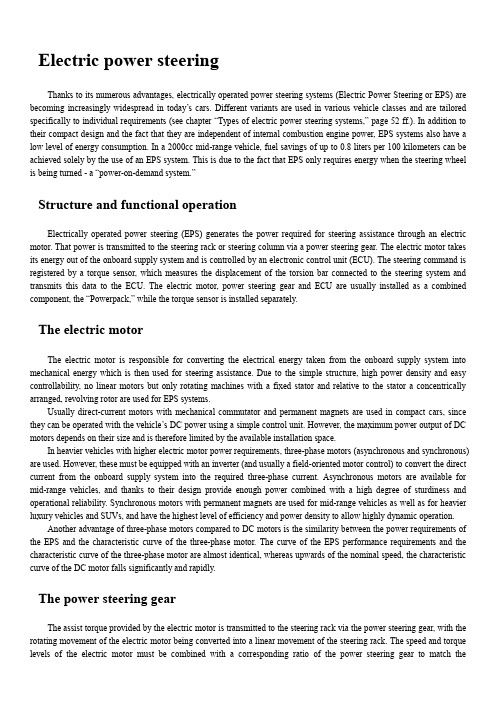
Electric power steeringThanks to its numerous advantages, electrically operated power steering systems (Electric Power Steering or EPS) are becoming increasingly widespread in today’s cars. Different variants are used in various vehicle classes and are tailored specifically to individual requirements (see chapter “Types of electric power steering systems,” page 52 ff.). In addition to their compact design and the fact that they are independent of internal combustion engine power, EPS systems also have a low level of energy consumption. In a 2000cc mid-range vehicle, fuel savings of up to 0.8 liters per 100 kilometers can be achieved solely by the use of an EPS system. This is due to the fact that EPS only requires energy when the steering wheel is being turned - a “power-on-demand system.”Structure and functional operationElectrically operated power steering (EPS) generates the power required for steering assistance through an electric motor. That power is transmitted to the steering rack or steering column via a power steering gear. The electric motor takes its energy out of the onboard supply system and is controlled by an electronic control unit (ECU). The steering command is registered by a torque sensor, which measures the displacement of the torsion bar connected to the steering system and transmits this data to the ECU. The electric motor, power steering gear and ECU are usually installed as a combined component, the “Powerpack,” while the torque sensor is installed separately.The electric motorThe electric motor is responsible for converting the electrical energy taken from the onboard supply system into mechanical energy which is then used for steering assistance. Due to the simple structure, high power density and easy controllability, no linear motors but only rotating machines with a fixed stator and relative to the stator a concentrically arranged, revolving rotor are used for EPS systems.Usually direct-current motors with mechanical commutator and permanent magnets are used in compact cars, since they can be operated with the vehicle’s DC power using a simple control unit. However, the maximum power output of DC motors depends on their size and is therefore limited by the available installation space.In heavier vehicles with higher electric motor power requirements, three-phase motors (asynchronous and synchronous) are used. However, these must be equipped with an inverter (and usually a field-oriented motor control) to convert the direct current from the onboard supply system into the required three-phase current. Asynchronous motors are available for mid-range vehicles, and thanks to their design provide enough power combined with a high degree of sturdiness and operational reliability. Synchronous motors with permanent magnets are used for mid-range vehicles as well as for heavier luxury vehicles and SUVs, and have the highest level of efficiency and power density to allow highly dynamic operation.Another advantage of three-phase motors compared to DC motors is the similarity between the power requirements of the EPS and the characteristic curve of the three-phase motor. The curve of the EPS performance requirements and the characteristic curve of the three-phase motor are almost identical, whereas upwards of the nominal speed, the characteristic curve of the DC motor falls significantly and rapidly.The power steering gearThe assist torque provided by the electric motor is transmitted to the steering rack via the power steering gear, with the rotating movement of the electric motor being converted into a linear movement of the steering rack. The speed and torque levels of the electric motor must be combined with a corresponding ratio of the power steering gear to match theperformance requirements of the steering system. Worm gears, ball and nut gears and toothed belt gears are used in EPS systems.In the case of a worm gear, the worm, which is shaped like a threaded bolt, engages in the worm wheel, which has teeth on its surface for that purpose. Worms used for EPS applications are made of hardened steel, but the teeth of the worm wheel are produced from high-performance plastic to reduce operating noise. Worm gears permit a large ratio with only one stage, but their efficiency level is not optimal.With an efficiency level of well over 90%, the ball and nut gear is considerably more efficient and also has a large ratio and a high level of mechanical stability. Ball and nut gears consist of a ball screw, an endless ball chain as a rolling element and a ball screw nut, including the return system for the ball chain and sealing elements. In EPS systems, the ball screw is designed as part of the steering rack, and the ball screw nut - referred to in these applications as a steering nut - is mounted around the ball screw via a ball bearing. The ball and nut gear is driven by the electric motor either directly or via a belt and pulley, where the steering nut rotates around the steering rack and the interposed ball chain converts the rotating motion into a linear motion of the steering rack.The additional interposition of a toothed belt gear into the ball and nut gear permits a second transmission stage, the ratio of which results from the size ratio of the two toothed disks.The electronic control unit (ECU)To control the electric motor, the EPS system has an ECU which calculates the necessary level of power assist through signal processing electronics and then supplies the requisite motor current via power electronics. A distinction is made between interior-mounted and engine compartment control units, mainly because of their temperature resistance, impermeability and resistance to various media such as oil, salt, etc., to which they are more (engine compartment units) or less (interior-mounted units) exposed.Preferably direct-mounted control units are being used, if possible in close proximity to the electric motor. In this way only short connection cables and fewer connectors are required, which reduces line losses and requires considerably less wiring. A stand-alone control unit is only installed in vehicles which do not have sufficient installation space available near the electric motor.To calculate the required level of power assist, the signal processing depends mainly on the information from the torque sensor. But the system is also connected to other ECUs in the vehicle via BUS interfaces, for example to the electronic stability program (ESP).This allows the detailed information about the current driving condition of the vehicle to be evaluated and processed by means of intelligent control and regulation algorithms. In this way a more refined control of the power assist level becomes possible.This can be used to adjust the required steering wheel torque (applied by the driver) to the current driving state, for example with a comfortable driving style, a lower steering wheel torque is required, while for a faster and sporty style, a higher torque will be necessary.The torque sensorA key parameter for calculation of the necessary power assist level in EPS systems is the steering wheel torque which the driver applies to the steering system by turning the steering wheel. This torque must be very precisely determined to give the driver a good steering feel and reassure him that his steering command is being directly implemented.Currently, only torque sensors with a mechanical torsion bar are used in EPS systems. They differ mainly in the method of measurement with which the torsion bar’s angle of rotation is determined during a steering operation. Torque sensors are available with potentiometric, inductive, magnetic and optical measurement, whereby because potentiometric sensors are not contactless and are thus subject to wear, they are only used nowadays for very low-cost EPS systems in com-pact cars.Inductive and magnetic measurement methods are based on measurement of magnetic field changes. In the case ofinductive measurement, the measurement takes place in an alternating magnetic field, while magnetic measurement is carried out in a static magnetic field. The advantages of both of these systems are that they use non-contact and therefore wear-free components, that they have a high degree of accuracy, and that they are impervious to dirt, water and oil.Optical measurement is performed using a light-emitting transmitter, for example an LED, and a light-sensitive receiver, for example a photodiode. A structured code disk, for example a stamped grid plate, is located between the transmitter and the receiver. The rotation of the torsion bar affects the light intensity between the transmitter and the receiver, and this change can be measured and evaluated in order to calculate the steering wheel torque. The advantage of optical sen-sors lies in their imperviousness to electro- magnetic interference. They are however very sensitive to contamination and to mechanical stress, so they can only be used within a limited temperature range.Types of electric power steering systemsThe types of electric power steering (EPS) systems differ in the location in which the servo unit is installed in the steering system. This is why they are called EPSc, EPSp, EPSdp, EPSapa and EPSrc - the lower-case suffixes describe the installation locations.EPSc - servo unit on the steering column (column)The first electric power steering system, the EPSc, was launched in the late 1980s and remains the most widely used EPS system in compact and mid-range vehicles. The servo unit including the torque sensor is located on the steering column and thus in the vehicle interior. This protects it from the environment; for example, it does not have to be waterproof and it is exposed to significantly lower temperature effects than those which exist in the engine compartment. One disadvantage here is, however, its proximity to the driver and the excessive distance to the steering gear.Its proximity to the driver can have an impact on safety if an accident occurs, because the distance to the steering gear results in a long transmission path for the forces via steering column, intermediate shaft and steering pinion. This limits the maximum achievable steering output. The assist torque from the electric motor to the steering column is generally transmitted via a worm gear.EPSp - servo unit on the steering pinion (pinion)In the EPSp, the assist torque of the electric motor is also transmitted by means of a worm gear, which in this case is directly connected to the steering pinion and the steering rack. This design eliminates the long transmission path, permitting higher steering forces compared to the EPSc. This design also enables the torque sensor to be directly combined with the servo unit.The installation options of the EPSp are subject to certain limitations, since the servo unit can only be rotated around the axis of the steering pinion. Furthermore, it is located in the driver’s footwell, so it needs to be ensured that the EPSp cannot penetrate into this area if an accident occurs, since this could lead to injury.Its position on the steering pinion means of course that the EPSp is located in the engine compartment, so it must meet higher demands regarding water tightness as well as resistance to temperature and vibration in this location. This also applies to all the types described below.EPSdp - servo unit on a second steering pinion (dual pinion)The limited installation options and the problematic accident safety issues of the EPSp led to development of the EPSdp design. Incorporating a second pinion into the steering system made it possible to place the sensor and the drive unit apart from one another. The torque sensor of the EPSdp is mounted on the actual steering pinion, from where it measuresthe steering wheel torque. The servo unit itself transmits the assist torque, but to the second pinion. Thanks to an appropriate worm gear design, the position of the servo unit relative to the rack-and-pinion and drive pinion axes can be adapted as required to fit the available installation space and to meet accident safety requirements.Another positive side-effect of this solution is a further increase in steering performance. The fact that the drive pinion ratio is independent of the steering ratio permitted the design of a performance-optimized drive ratio.EPSapa - servo unit with axis-parallel drive of the steering rack (axis parallel)A low level of system friction and a high degree of efficiency characterize the EPSapa design. This is why it is mainly used in vehicles with high steering assist requirements, such as sports cars, SUVs, upper mid-range cars and vans. As the name implies, the electric motor is mounted axially parallel to the steering rack, and the steering assistance is transmitted di-rectly to the steering rack by means of a ball screw drive equipped with a belt drive. This combination of ball screw drive and belt drive permits an additional transmission stage, and this is what creates the high level of efficiency (see chapter “The power steering gear”, page 46 ff.). As in the EPSdp, the torque sensor is located on the steering pinion and separated from the assist mechanism.Besides its high level of efficiency, the EPSapa offers optimum use of the available installation space. The motor parallel to the steering rack nestles up close to the rack and can be arranged around it depending on the space available.EPSrc - servo unit with concentric drive of the steering rack (rack concentric)The EPSrc is a particularly compact design in which the servo unit is arranged around the steering rack. However, this design requires a special electric motor with hollow shaft, since the rack passes through it. The motor power is transmitted directly to the steering rack via a ball screw drive. Since the additional transmission stage is not present, unlike in the EPSapa with its ball screw gear and belt drive, the electric motor requires a much higher torque to achieve a similar level of steering assistance.System safetyEach EPS system must be designed in such a way that safety-critical states can be ruled Ruling out of out during operation according to the state safety-critical of the art. A safety-critical state is considered any instance where the vehicle’s characteristics diverge so far from the normal state that the driver is unable to control the vehicle, creating a risk of danger to life, limb and property.ISO 26262 safety requirementsEPS systems, as safety-relevant electrical or electronic systems, are subject to the ISO 26262 standard, which governs the functional safety of motor vehicles. ISO 26262 states that the safety of an electrical or electronic system in the vehicle cannot be ensured by external safety measures, but must be an integral part of the system itself.For compliance with these requirements, the ISO 26262 standard defines a procedural model including its required activities, plus the methods to be used for the development and production of electrical and electronic systems in motor vehicles. Also defined in this standard are safety requirement levels, which are used to classify electrical and electronic systems. From these requirement levels, safety objectives are derived. The levels range from “QM” (quality measure) fornon-safety-relevant requirements to “ASIL D,” the highest possible safety requirement level (ASIL stands for Automotive Safety Integrity Level).Without taking into account safety measures, the associated risk for the overall system is first determined in line with ISO 26262 using a hazard and risk analysis. Based on the analysis results, classification of the system into one of the safety requirement levels, “QM” to “ASIL D,” follows. The next step is the development of a safety concept that minimizes the existing risk for the overall system to a calculable level by means of integrated safety-related measures. The effectiveness of this safety concept must be documented by a safety check, the scope of which is in turn specified by the previously determined safety requirement level.Risk classification of EPS systemsThe assessment of the overall system risk posed by EPS systems (as per ISO 26262) results in a classification into the highest safety requirement level, “ASIL D.” Individual potential fault scenarios are considered and, for example, evaluated as follows:• Unwanted activation of the electric motor leads to an “ASIL D” classification.• Sluggishness of the steering system caused by faulty activation of the electric motor also results in an “ASIL D”classification.• A sudden start of the steering assistance system receives an “ASIL A”, classification.• A failure of the steering power assist system is ultimately a qu ality measure, “QM.”These classifications only address risks related to malfunctions of the electrical or electronic system. Mechanical failures are not in-' eluded in the risk analysis and are excluded by appropriate standards for the mechanical design and structural measures defined therein. One important result of the risk analysis is the establishment of protection goals along with the assignment of the appropriate safety requirement level:• ASIL: All safety measures that contribute to ensuring the protection goal “inherit” the appropriate safety requirement level, which affects the required development process, quality, and residual fault probability of the safety measure. The higher the ASIL classification, the higher the requirements.• QM: These objectives are not addressed by ISO 26262, but must be rectified by quality assurance measures.In EPS systems, purely mechanical steering without steering power assist is available as a fail-back option. As such, the safety concept of EPS systems is considered to be a fail-safe principle, i.e. the steering power assist is switched off during a critical fault scenario. The driver then still has a fully functioning steering system at his disposal, albeit a more sluggish and purely mechanical one. A complete shutdown is rarely required. The switching off sub-functions, for example, will very often counteract a malfunction and restore the system to a safe operating state.As a result, an elaborate monitoring concept is used to carry out a fault diagnostic program aimed at determining the cause of the fault. Faults can be caused by both the EPS system and by external signals, which are evaluated and processed by the control unit. The system is then either partially or completely disabled via shutdown paths, with the type of shutdown depending on the results of the fault diagnosis and the safety measures associated with each. Defined fault tolerance times ensure that fault detection and operation of the shutdown paths take place within an acceptably short time frame, ensuring that no danger can arise for the driver.Steering functions and their controlAs in hydraulic power steering systems, EPS systems should assist the driver while steering the car, giving the maximum possible feeling of safety for the current driving situation. EPS has, however, more options than the required “basic steering functions.” These options are subdivided into “advanced steering functions” and “vehicle level functions.”The basic steering functions will not be discussed in detail at this juncture because they have already been covered in detail in the chapters entitled, “Principles of driving physics,”“Factors influencing driving feel”and “The hydraulic power steering system.”Advanced steering functionsThe advanced features of an EPS system include, in particular, measures to relieve the driver of the burden of making steering corrections during normal driving. The main features here are “Active Return”and “Straight-line Stability Correction.”A vehicle will usually return to straight-ahead driving by itself when the steering wheel is released after a steering command, even if the driver does not carry out the appropriate steering movements. The suspension design of modem vehicles, however, often yields an unsatisfactory response while returning to straight-ahead driving, particularly at low speeds. Depending on the suspension design, this can even lead to the steered wheels remaining in the turned position once the driver exceeds a certain steering angle. As a result, EPS systems have an active return function: If the control unit determines that this driving situation applies, the EPS system automatically assists the return of the steered wheels to the straight-ahead direction. It is crucial that the active return function gently returns the steering wheel, whether released or still held by the driver, to the straight-ahead position. This means, for example, that if the steering wheel is being held, all steering wheel movements and inputs, ranging from slight torques applied by the driver to a heavy grip holding the wheel firmly, are properly considered, so that the function does not overpower the driver.All roads have some lateral slope (camber) for proper rainwater runoff. A vehicle will follow this slope in straight-ahead driving, forcing the driver in this case to slightly countersteer against the inclination (never actually straight ahead). As such, the driver must constantly apply a torque, however slight, to the steering wheel to maintain a straight driving direction. The straight-line stability correction function in the EPS system relieves the driver of this task, enabling him to hold the steering wheel in a torque- free and effortless manner during straight-ahead driving. However, if straight-line stability correction is to function correctly, detection of the roadway gradient in question is essential, as this determines the necessary correction in the steering system.Vehicle level functionsIntegration of the EPS system as an intelligent element into the overall vehicle system permits not only steering assist functions, but also other driver aid functions, such as those which warn the driver of critical situations and help cope with them, or which even relieve the driver of complete driving operations.Lane departure warning is one example: On long freeway journeys, fatigue and lack of concentration can lead to a driver unintentionally leaving the intended traffic lane, which is a common cause of accidents. A warning system uses a camera to permanently monitor the position of the vehicle relative to the lane boundaries and detects when the vehicle is threatening to leave the lane. An appropriate warning is sent to the control device of the EPS, which then applies an addi-tional torque to the steering in the direction of the lane center. A vibration alarm can also be superimposed as an additional warning. This function is much more effective than just a vibration alarm, since the driver is given a recommendation in addition to the warning. Lane guidance functions take this concept one step further. They not only warn the driver of unintentional departure from the lane, but also use active steering assistance to keep the vehicle in the lane. Due to the current regulatory situation, however, autonomous lane guidance by the system is not yet permitted; assistance is only provided for the driver when the driver’s hands are on the steering wheel.Another EPS function at the vehicle level is the dynamic steering recommendation, where the EPS system gives the driver a ‘tip’ for the correct steering movement by means of a short torque pulse at the steering wheel. If, for example, the electronic control system of the vehicle determines that countersteering is required in a driving scenario, a short torque pulse prompts the driver to countersteer in the appropriate direction.It goes without saying that with all of these vehicle-level functions, the initiated pulses must not be triggered during any critical driving situations. The pulses must be perceived by the driver but should not startle in any way that could trigger incorrect responses. Even with active assistance, the driver must still remain in command of the driving situation and be able to nullify the steering torques at all times.The operation of the parking assist function contradicts these requirements. It actually takes over the vehicle’s steeringsystem, in particular while backing into a parking space at the curb. The driver can focus fully on operating the accelerator, brakes, and clutch. A position sensor system first determines the size of the parking space using ultrasonic sensors. It also determines whether or not any obstacles are present and the position of the vehicle in relation to the parking space. From this data, the control unit then calculates the required steering motion and controls the EPS system accordingly. During parking, this data must be continually evaluated and adapted to the current driving state, for example to take into account the driver’s accelerator and braking commands. In addition, safety must be ensured at all times. The turning of the steering wheel during the parking maneuver must not be able to injure the driver if a hand is accidentally reached into the wheel.Control conceptsAs with the basic steering functions, the “classic”control concept for EPS is also derived from the principles of hydraulic power steering. Depending on the steering wheel torque applied by the driver, a corresponding assist force is applied by the EPS system. The ratio between the steering wheel torque applied by the driver and the assist force is not linear but progressive, meaning that as steering wheel torque increases the assist force increases at a proportionately higher rate.In this concept, steering control is very closely linked to steering feel. Any modification to the steering feel always requires an intervention in the control system itself. This fact is the reason why any modification of the steering feel (i.e. vibrations in the steering wheel or torque pulses), which is requested by any of the vehicle-level steering functions, can only be carried out indirectly with the classic control concept.If the control concept is split into two independent components, steering feel and steering control, the requested torque interventions can be carried out directly without interaction with the control system.电动助力转向系统由于其众多的优点,电动的助力转向系统EPS 电动助力转向系统)正在变得越来越普遍在今天的汽车。
电动助力转向简介
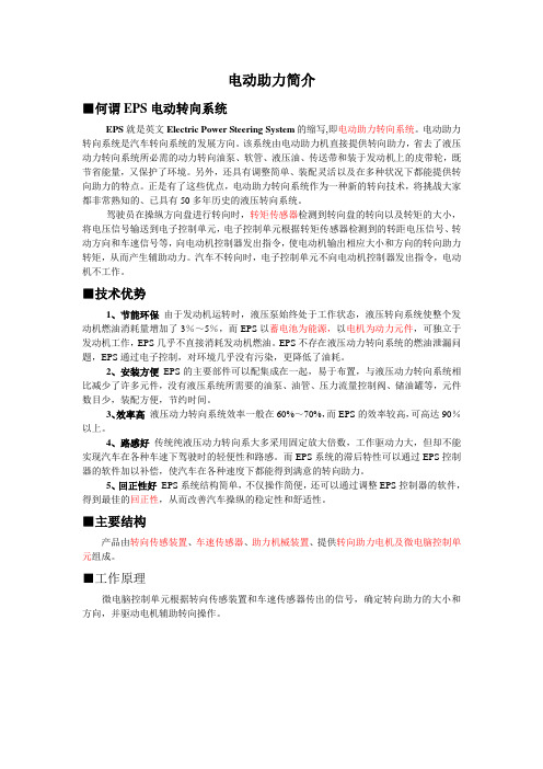
电动助力简介■何谓EPS电动转向系统EPS就是英文Electric Power Steering System的缩写,即电动助力转向系统。
电动助力转向系统是汽车转向系统的发展方向。
该系统由电动助力机直接提供转向助力,省去了液压动力转向系统所必需的动力转向油泵、软管、液压油、传送带和装于发动机上的皮带轮,既节省能量,又保护了环境。
另外,还具有调整简单、装配灵活以及在多种状况下都能提供转向助力的特点。
正是有了这些优点,电动助力转向系统作为一种新的转向技术,将挑战大家都非常熟知的、已具有50多年历史的液压转向系统。
驾驶员在操纵方向盘进行转向时,转矩传感器检测到转向盘的转向以及转矩的大小,将电压信号输送到电子控制单元,电子控制单元根据转矩传感器检测到的转距电压信号、转动方向和车速信号等,向电动机控制器发出指令,使电动机输出相应大小和方向的转向助力转矩,从而产生辅助动力。
汽车不转向时,电子控制单元不向电动机控制器发出指令,电动机不工作。
■技术优势1、节能环保由于发动机运转时,液压泵始终处于工作状态,液压转向系统使整个发动机燃油消耗量增加了3%~5%,而EPS以蓄电池为能源,以电机为动力元件,可独立于发动机工作,EPS几乎不直接消耗发动机燃油。
EPS不存在液压动力转向系统的燃油泄漏问题,EPS通过电子控制,对环境几乎没有污染,更降低了油耗。
2、安装方便EPS的主要部件可以配集成在一起,易于布置,与液压动力转向系统相比减少了许多元件,没有液压系统所需要的油泵、油管、压力流量控制阀、储油罐等,元件数目少,装配方便,节约时间。
3、效率高液压动力转向系统效率一般在60%~70%,而EPS的效率较高,可高达90%以上。
4、路感好传统纯液压动力转向系大多采用固定放大倍数,工作驱动力大,但却不能实现汽车在各种车速下驾驶时的轻便性和路感。
而EPS系统的滞后特性可以通过EPS控制器的软件加以补偿,使汽车在各种速度下都能得到满意的转向助力。
中英文文献翻译-汽车电动助力转向系统发展综述
附录A 外文文献Overview ofDevelopment on Vehicle EPS SystemAbstractThe currentdevelopment of an electric power steering(EPS) system in an automobile is explicated. The structure, types and characteristics of electric power steering system are introduced. The modeling technologies for electric power steering system and control strategies are analyzed and compared. The development trend of electric power steering system in an automobile is also discussed. It is pointed that the electric power steering technology is one orientation ofpower steering technologies in the future, and whichwill occupy a predominantposition in power steering field.Key words:Automobile; Electric power steering system; Development trend1EPS system types and characteristics1.1EPS system classificationThe early development of EPS system is low in steering type car。
转向系统的发展外文文献翻译、中英文翻译、外文翻译
的动态特征时,以低段参数效果不是很好,如果没有,目标车辆液压系统也必须在发动机驱动。
因此,能源消耗,增加燃料发动机,现有的液压油泄漏问题应该不仅污染环境,而且容易影响其他组件。
针对低温,液压系统性能很差。
近年来,随着电子技术的广泛应用,转向系统也越来越多的使用电子设备。
因此,变成使用电子控制系统出现相应的电动液压助力转向系统。
电动液压动力转向系统可以分为两类:电动液压操舵系统(电液压动力(EHPS)和电动液压转向电子控制转向(液压动力转向)。
电动液压操舵系统在液压动力系统的基础上开发的液压增压系统,不同的是,电动液压系统液压系统的电源,但不是由汽车发动机汽车驱动液压系统,节约能源,降低发动机油耗。
电动液压操舵装置是在传统的液压助力系统的基础上开发,所不同的是,电动液压操舵系统,电子控制设备增加。
电子控制单元可以根据转向速度,速度的汽车液压系统的操作参数,改变液压增压速度不同的大小,从而实现变化,动态特征。
但根据电机驱动液压系统,反过来,电机停止转动,从而减少能源消耗。
虽然电动液压动力转向液压操舵系统克服了缺点。
但由于液压系统的存在,它的存在液压油泄漏问题,和电动液压助力转向系统,介绍了电机驱动系统更复杂,成本和可靠性。
为了区别电动液压转向系统、电动助力转向系统电动助力转向(EPS)。
现在应该知道各种各样的转向系统,最大的区别在于电动助力转向系统没有液压系统。
最初由液压操舵系统的电动机。
电动助力转向系统一般由扭矩传感器和微处理器、电机、等的基本原理是:当司机将方向盘驱动轴旋转,安装在转动轴的扭矩传感器和扭矩信号到电信号微处理器,微处理器基于其他车辆运行速度和扭矩信号的参数,根据治疗的程序集电力汽车助推器方向和大小的助推器。
自1988年以来,第一次在日本铃木Cervo汽车装备转向系统、动力转向系统被广泛承认的人。
转向系统主要体现在以下方面:动力转向系统可以提供不同在不同速度下的动态特性。
低,方向盘,增加更多的光,在高速转向减少,甚至为了提高道路增加潮湿。
- 1、下载文档前请自行甄别文档内容的完整性,平台不提供额外的编辑、内容补充、找答案等附加服务。
- 2、"仅部分预览"的文档,不可在线预览部分如存在完整性等问题,可反馈申请退款(可完整预览的文档不适用该条件!)。
- 3、如文档侵犯您的权益,请联系客服反馈,我们会尽快为您处理(人工客服工作时间:9:00-18:30)。
附录A 外文文献Electric Power Steering system1.HistoryIn automobile development course, Steering system experienced four stages of development: from the initial mechanical Steering system (for your DNS setting Steering, abbreviation ) development for Hydraulic Steering system (Hydraulic Power Steering, abbreviation HPS), then again appeared electronically controlled Hydraulic Steering system (Electro Hydraulic Power Steering, abbreviation EHPS) and Electric Power Steering system (Steering, room Power as EPS). Assemble mechanical steering system of car parking and low-speed driving, when the driver's steering control burden too heavy, in order to solve this problem, the American GM in the 1950s took the lead in the car hydraulic steering system. But, hydraulic steering system can't juggle vehicles to speed portability and high speed, so the steering stability Koyo in Japan in 1983, with the company introduced the application of speed sensing function of hydraulic steering system. This new type of steering system can provide speed increased with the decreasing steering, but complicated structure, cost is higher, and cannot overcome hydraulic system itself has many shortcomings, is a cross between a hydraulic steering and electric power steering the transition between the products. In 1988, Japan Suzuki company first in small cars equipped with Cervo Koyo company development on the steering column, power type electric power steering system; In 1990, Japan Honda NSX in sports car company adopted self-developed rack power type electric power steering system, henceforth unveils the electric power steering in cars applications history2.Working principleElectric power steering system are as follows: first, the working principle, torque sensor measured on steering wheel drivers on the manipulation of the moment, the wheel speed sensors detect the vehicle driving speed, then present the two signals to ECU; According to the built-in control strategy: ECU, calculates the ideal target booster torque, into current instructions to motor; Then, the power generated by the torque motor slowdown institutions amplification on steering system in mechanical manipulation of the moment, and the driver together to overcome resistance torque, realize to the vehicle steering.3. Working processElectric power steering system as traditional hydraulic system alternative products has entered into the auto manufacturing. And had predicted instead, EPS not only applicable to small cars, and some for 12V medium vehicle installed electric system.EPS system includes the following components:The torque sensor: detection steering wheel motion and vehicle motion situation;Electronic control units: according to provide the torque sensor the size of the signal computing power;Motor: according to the electronic control units; turn power output value generation Reduction gear: improve motor power, and produce turn it sends to steering mechanism.Other vehicle system control algorithm input information is provided by the car CAN bus (for example steering Angle and bus speed, etc.). Motor drive also need other information, such as motor rotor position and the three-phase motor sensor (current sensor provided). Motor control by four MOSFET, due to micro controller cannot direct drive of large gate capacitance, MOSFET using drive IC form needed the interface, for safety, complete motor control system must implement monitoring, motor control system integration in PCB, usually contains a relay, the relay use, as the main switch under the condition of the fault detection, disconnect motor and electronic control units.Micro control device must control EPS system and have brushless motor. Micro control device according to the torque sensor provide needed the steering wheel torque information, forming a current control loop. In order to improve the security of the system level, the micro control device should have an on-board oscillator, so even in external oscillator malfunction case, also ensure micro control device performance, also should have chip watchdog. Infineon XC886 integration of the company all the important micro control device component, other safety features for through the software to realize, if must implement safety standards IEC61508 industries, you have to finish all kinds of diagnosis and self-inspection task and increase micro control device work load. At present different customers use of torque sensor and rotor position sensor difference is very big. They use different measuring principle, such as decomposing machine, magnetic resonance device, based on the integration of giant magnet or stance sensor.The role of power levels is switch electric current. The power level has two main functions: drive IC control and protection MOSFET, MOSFET itself and to be responsible for switch currents. MOSFET and partition.Micro control device PWM output port provides driver current and voltage is too low, can't directly connected with MOSFET screen realization. Drive IC role is to provide enough current, the grid to charge for MOSFET, so that in the and discharge 20kHz conditions, and ensure the normal realization switch for discretion side provides the high bar source voltage MOSFET, ensure that you get the low conduction resistance. If the high side MOSFET in open state, to source potential close battery level. Want to make MOSFET arrived at nominal conduction resistance, gate to higher than 8V source voltage. MOSFET completely conduction needed the most ideal voltage is required, therefore 10V or above a grid of potential than battery voltage 10V is higher. Charge pump is to ensure that the function to the largest extent reduce MOSFET power (even if low battery voltage conditions) circuit.The other key charge pump design according to different characteristics that can be PWM pattern request, achieve extremely low (low to 1%) and high rate of 390v (high to 100%). Drive IC another important function is testing, avoid damage to short-circuit mosfets, affected MOSFET will be closed, diagnosis submitted to micro control device.附录B 外文文献的中文翻译电动助力转向系统1.发展历史在汽车的发展历程中,转向系统经历了四个发展阶段:从最初的机械式转向系统(Manual Steering,简称MS)发展为液压助力转向系统(Hydraulic Power Steering,简称HPS),然后又出现了电控液压助力转向系统(Electro Hydraulic Power Steering,简称EHPS)和电动助力转向系统(Electric Power Steering,简称EPS)。