OSPF配置实验
路由器R4---OSPF动态路由协议配置实验

OSPF动态路由配置一、实验名称:OSPF动态路由配置二、实验目的1、掌握OSPF动态路由的配置2、知道什么情况下适合使用OSPF动态路由三、网络拓朴四、实验设备1、四台路由器(每台配置4个以太网接口)2、四台安装有 windows 98/xp/2000操作系统的主机3、若干直连、交叉网线五、实验过程1、选择2811路由器2台。
每台添加WIC-1T模块一个。
2、将路由器、主机根据如上图示进行连接。
3、设置主机的IP地址、子网掩码和默认网关4、三层交换机S3560接口配置Switch>enSwitch#conf tSwitch(config)#hostname S3560Enter configuration commands, one per line. End with CNTL/Z.S3560(config)#vlan 10S3560(config-vlan)#exitS3560(config)#vlan 20S3560(config-vlan)#exitS3560(config)#int f0/10S3560(config-if)#switchport access vlan 10S3560(config-if)#exitS3560(config)#int f0/20S3560(config-if)#switchport access vlan 20S3560(config-if)#exitS3560(config)#ip routing //启用三层交换机路由功能S3560(config)#interface vlan 10S3560(config-if)#ip address 192.168.1.2 255.255.255.0 S3560(config-if)#no shutdownS3560(config-if)#exitS3560(config)#interface vlan 20S3560(config-if)#ip address 192.168.3.1 255.255.255.0 S3560(config-if)#no shutdownS3560(config-if)#exit5、路由器R1接口配置Router>enRouter#conf tRouter(config)#hostname R1R1(config)#interface f0/0R1(config-if)#ip address 192.168.3.2 255.255.255.0R1(config-if)#no shutdownR1(config-if)#exitR1(config)#interface s0/2/0R1(config-if)#clock rate 64000R1(config-if)#ip address 192.168.4.1 255.255.255.0R1(config-if)#no shutdownR1(config-if)#exit6、路由器R2接口配置Router>enRouter#conf tRouter(config)#hostname R2R2(config)#interface f0/0R2(config-if)#ip address 192.168.2.1 255.255.255.0R2(config-if)#no shutdownR2(config-if)#exitR2(config)#interface s0/2/0R2(config-if)#ip address 192.168.4.2 255.255.255.0R2(config-if)#no shutdownR2(config-if)#exit7、三层交换机的OSPF的配置S3560(config)#router ospf 1 //启用OSPF协议S3560(config-router)#log-adjacency-changes //令可用来激活路由协议邻接关系变化日志的功能(例如ospf或者ISIS等)S3560(config-router)#network 192.168.1.0 0.0.0.255 area 0S3560(config-router)#network 192.168.3.0 0.0.0.255 area 08、路由器R1的RIP的配置R1(config)#router ospf 1 //启用OSPF协议R1(config-router)#log-adjacency-changes //令可用来激活路由协议邻接关系变化日志的功能(例如ospf或者ISIS等)R1(config-router)#network 192.168.3.0 0.0.0.255 area 0R1(config-router)#network 192.168.4.0 0.0.0.255 area 09、路由器R2的RIP的配置R2(config)#router ospf 1 //启用OSPF协议R2(config-router)#log-adjacency-changes //令可用来激活路由协议邻接关系变化日志的功能(例如ospf或者ISIS等)R2(config-router)#network 192.168.4.0 0.0.0.255 area 0R2(config-router)#network 192.168.2.0 0.0.0.255 area 010、查看三层交换机S3560路由表信息S3560#show ip routeCodes: C - connected, S - static, I - IGRP, R - RIP, M - mobile, B - BGPD - EIGRP, EX - EIGRP external, O - OSPF, IA - OSPF inter areaN1 - OSPF NSSA external type 1, N2 - OSPF NSSA external type 2E1 - OSPF external type 1, E2 - OSPF external type 2, E - EGPi - IS-IS, L1 - IS-IS level-1, L2 - IS-IS level-2, ia - IS-IS inter area* - candidate default, U - per-user static route, o - ODRP - periodic downloaded static routeGateway of last resort is not setC 192.168.1.0/24 is directly connected, Vlan10O 192.168.2.0/24 [110/66] via 192.168.3.2, 00:04:35, Vlan20C 192.168.3.0/24 is directly connected, Vlan20O 192.168.4.0/24 [110/65] via 192.168.3.2, 00:04:35, Vlan2011、查看路由器R1路由表信息R1#show ip routeCodes: C - connected, S - static, I - IGRP, R - RIP, M - mobile, B - BGPD - EIGRP, EX - EIGRP external, O - OSPF, IA - OSPF inter areaN1 - OSPF NSSA external type 1, N2 - OSPF NSSA external type 2E1 - OSPF external type 1, E2 - OSPF external type 2, E - EGPi - IS-IS, L1 - IS-IS level-1, L2 - IS-IS level-2, ia - IS-IS inter area * - candidate default, U - per-user static route, o - ODRP - periodic downloaded static routeGateway of last resort is not setO 192.168.1.0/24 [110/2] via 192.168.3.1, 00:02:12, FastEthernet0/0O 192.168.2.0/24 [110/65] via 192.168.4.2, 00:15:39, Serial0/2/0C 192.168.3.0/24 is directly connected, FastEthernet0/0C 192.168.4.0/24 is directly connected, Serial0/2/012、查看路由器R2路由表信息R2#show ip routeCodes: C - connected, S - static, I - IGRP, R - RIP, M - mobile, B - BGPD - EIGRP, EX - EIGRP external, O - OSPF, IA - OSPF inter areaN1 - OSPF NSSA external type 1, N2 - OSPF NSSA external type 2E1 - OSPF external type 1, E2 - OSPF external type 2, E - EGPi - IS-IS, L1 - IS-IS level-1, L2 - IS-IS level-2, ia - IS-IS inter area * - candidate default, U - per-user static route, o - ODRP - periodic downloaded static routeGateway of last resort is not setO 192.168.1.0/24 [110/66] via 192.168.4.1, 00:02:40, Serial0/2/0C 192.168.2.0/24 is directly connected, FastEthernet0/0O 192.168.3.0/24 [110/65] via 192.168.4.1, 00:02:50, Serial0/2/0C 192.168.4.0/24 is directly connected, Serial0/2/013、其他查看配置信息命令Router#show ip route //查看路由器的路由表Router#show ip route rip //查看路由表中通过RIP路由协议学习到的路由Router#show ip protocol //查看路由器开启的路由协议Router#show ip ospf neighbor //查看与本路由器是“邻居”关系的路由器Router#show ip ospf interface //查看区域号和与此相关的信息Router#show ip ospf database //查看前路由器ospf的数据库信息Router#clear ip route * //清除路由表中通过路由协议学习到的路由14、进行主机间ping测试15、跟踪PC1 PC2的数据包转发过程PC> tracert 192.168.2.2。
实验 OSPF路由协议的配置与应用

OSPF路由协议的配置与应用一、实验目的1.理解三层交换机的工作原理;2.理解OSPF路由协议的工作原理;3. 掌握虚拟局域网VLAN的设置;4.掌握OSPF路由协议的配置方法。
二、实验内容1. 根据网络拓扑图,组建网络;2. 配置VLAN、设备互联地址、模拟终端IP地址;3. 配置OSPF路由协议,计算动态路由表;4. 测试网络互联互通。
三、实验步骤1、根据网络拓扑图,组建网络。
如图所示,其中路由器Router1和Router3之间使用V.35 DTE/DCE线缆进行连接,三层交换机Switch中端口Ethernet1/0/1~Ethernet1/0/2属于VLAN 20,而端口Ethernet 1/0/24属于VLAN 10。
2.三层交换机Switch的配置#进入系统视图<Switch >system-view#创建VLAN 10,并配置接口IP地址[Switch]vlan 10[Switch-vlan10] interface vlan-interface 10[Switch -Vlan-interface10]ip address 192.168.111.2 255.255.255.252#将端口Ethernet 1/0/24加入到VLAN 10中[Switch -Vlan-interface10]vlan 10[Switch-vlan10]port Ethernet 1/0/24#创建VLAN 20,并配置接口IP地址[Switch -Vlan-interface10]vlan 20[Switch-vlan20]interface vlan-interface 20[Switch –Vlan-interface20]ip address 192.168.112.1 255.255.255.0 #将端口Ethernet 1/0/1~1/0/2加入到VLAN 20中[Switch –Vlan-interface20]vlan 20[Switch-vlan20] port Ethernet 1/0/1 to Ethernet 1/0/2#退出VLAN视图,进入系统视图[Switch-vlan20]quit#配置交换机Router-ID[Switch]router id 1.1.1.1#创建OSPF进程并进入OSPF视图[Switch]ospf#在OSPF视图下创建区域0并进入区域视图[Switch-ospf-1]area 0#指定属于该区域的接口网段[Switch-ospf-1]network 192.168.111.0 0.0.0.3[Switch-ospf-1]network 192.168.112.0 0.0.0.2553.路由器Router1的配置#进入系统视图<Router1>system-view#配置端口Ethernet 0/1的IP地址[Router1]interface ethernet 0/1[Router1-Ethernet0/1]ip address 192.168.111.1 255.255.255.252#配置端口Serial 1/0的IP地址[Router1-Ethernet0/1]interface serial 1/0[Router1-Serial1/0]ip address 202.1.1.1 255.255.255.252#配置路由器Router-ID[Router1-Serial1/0]quit[Router1]router id 2.2.2.2#创建OSPF进程并进入OSPF视图[Router1]ospf#在OSPF视图下创建区域0并进入区域视图[Router1-ospf-1]area 0#指定属于该区域的接口网段[Router1-ospf-1-area-0.0.0.0]network 192.168.111.0 0.0.0.3[Router1-ospf-1-area-0.0.0.0]network 202.1.1.0 0.0.0.34.路由器Router2的配置#进入系统视图<Router2>system-view#配置以太网接口0/1的IP地址[Router2]interface loopback 0[Router2-Loopback0]ip address 192.168.113.1 255.255.255.255#配置端口Serial 1/0的IP地址[Router2]interface serial 1/0[Router2-Serial1/0]ip address 202.1.1.2 255.255.255.252#配置路由器Router-ID[Router2-Serial1/0]quit[Router2]router id 3.3.3.3#创建OSPF进程并进入OSPF视图[Router2]ospf#在OSPF视图下创建区域0并进入区域视图[Router2-ospf-1]area 0#指定属于该区域的接口网段[Router2- ospf-1-area-0.0.0.0]network 202.1.1.0 0.0.0.3 [Router2- ospf-1-area-0.0.0.0]network 192.168.113.0 05.实验结果验证1) 查看三层交换机Switch的路由表[Switch] display ip routing-tableRouting Tables: PublicDestinations :8 Routes : 82) 查看路由器Router1的路由表[Router1] display ip routing-tableRouting Tables: PublicDestinations : 9 Routes : 93) 查看路由器Router2的路由表[Router2] display ip routing-tableRouting Tables: PublicDestinations : 9 Routes : 94) 在PC1的“命令提示符”下输入ping 192.168.103.2,结果如图4-15所示;反之,从PC3同样可以ping通PC1和PC2。
实验11 ospf综合实验

OSPF综合实验一、实验拓扑图,如图1.1所示:图1.1 ospf综合实验拓扑图二、实验要求:1.要求全网互通2.R1、R5之间链路断开后,全网仍能互通3.R2永远为DR4.区域34为NSSA区域5.在区域0中仅出现2.2.0.0/22 的汇总路由6.除R3之外,所有路由仅有3.3.0.0/22的路由7.区域0中所有接口及虚链路做密文认证,认证密钥为cisco8.在R5上产生默认路由三、实验配置:1.预配置://R1上的预配置R1(config)#int lo 0R1(config-if)#ip add 1.1.1.1 255.255.255.0R1(config-if)#int s3/0R1(config-if)#ip add 123.0.0.1 255.255.255.0R1(config-if)#no shR1(config-if)#int s2/2R1(config-if)#ip add 15.0.0.1 255.255.255.0R1(config-if)#no sh//R2上的预配置R2(config)#int lo 0R2(config-if)#ip add 2.2.0.2 255.255.255.0 R2(config-if)#int lo 1R2(config-if)#ip add 2.2.1.2 255.255.255.0 R2(config-if)#int lo 2R2(config-if)#ip add 2.2.2.2 255.255.255.0 R2(config-if)#int lo 3R2(config-if)#ip add 2.2.3.2 255.255.255.0 R2(config-if)#int s3/0R2(config-if)#ip add 123.0.0.2 255.255.255.0 R2(config-if)#no shR2(config-if)#int f0/0R2(config-if)#ip add 25.0.0.2 255.255.255.0 R2(config-if)#no sh//R3上的预配置R3(config)#int lo 0R3(config-if)#ip add 3.3.0.3 255.255.255.0 R3(config-if)#int lo 1R3(config-if)#ip add 3.3.1.3 255.255.255.0 R3(config-if)#int lo 2R3(config-if)#ip add 3.3.2.3 255.255.255.0 R3(config-if)#int lo 3R3(config-if)#ip add 3.3.3.3 255.255.255.0 R3(config-if)#int s3/0R3(config-if)#ip add 123.0.0.3 255.255.255.0 R3(config-if)#no shR3(config-if)#int s2/2R3(config-if)#ip add 34.0.0.3 255.255.255.0 R3(config-if)#no sh//R4上的预配置R4(config)#int lo 0R4(config-if)#ip add 4.4.4.4 255.255.255.0 R4(config-if)#int f0/0R4(config-if)#ip add 25.0.0.4 255.255.255.0 R4(config-if)#no shR4(config-if)#int s2/1R4(config-if)#ip add 34.0.0.4 255.255.255.0 R4(config-if)#no sh//R5上的预配置R5(config)#int lo 0R5(config-if)#ip add 5.5.5.5 255.255.255.0 R5(config-if)#int lo 1R5(config-if)#ip add 10.0.0.1 255.255.255.0R5(config-if)#int f0/0R5(config-if)#ip add 25.0.0.5 255.255.255.0R5(config-if)#no shR5(config-if)#int s2/1R5(config-if)#ip add 15.0.0.5 255.255.255.0R5(config-if)#no sh2.各路由器的上的具体配置://R1上的具体配置R1(config)#interface Loopback0R1(config-if)# ip ospf authentication message-digest //启用链路MD5认证R1(config-if)# ip ospf message-digest-key 1 md5 cisco //配置key ID及密匙R1(config-if)#interface Serial2/2R1(config-if)# ip ospf authentication message-digestR1(config-if)# ip ospf message-digest-key 1 md5 ciscoR1(config-if)#interface Serial3/0R1(config-if)# encapsulation frame-relay //帧中继封装R1(config-if)# frame-relay map ip 123.0.0.2 102 broadcast //帧中继类型配置为广播R1(config-if)# no arp frame-relay //关闭ARPR1(config-if)# no frame-relay inverse-arp//关闭inverse-arpR1(config-if)# ip ospf network broadcast //配置OSPF网络位broadcastR1(config-if)# ip ospf priority 0 //S3/0的DR/BDR的选举权R1(config-if)#router ospf 1R1(config-router)# router-id 1.1.1.1R1(config-router)# area 123 range 2.2.0.0 255.255.252.0//配置虚链路且开启md5认证R1(config-router)#$irtual-link 2.2.2.2 message-digest-key 1 md5 ciscoR1(config-router)# network 1.1.1.1 0.0.0.0 area 0R1(config-router)# network 15.0.0.1 0.0.0.0 area 0R1(config-router)# network 123.0.0.1 0.0.0.0 area 123//R2上的具体配置R2(config-if)#interface Serial3/0R2(config-if)# encapsulation frame-relayR2(config-if)# ip ospf network broadcastR2(config-if)# ip ospf priority 10R2(config-if)# no arp frame-relayR2(config-if)# frame-relay map ip 123.0.0.1 201 broadcastR2(config-if)# frame-relay map ip 123.0.0.3 203 broadcastR2(config-if)# no frame-relay inverse-arpR2(config-if)#router ospf 1R2(config-router)# router-id 2.2.2.2R2(config-router)#$rtual-link 5.5.5.5 message-digest-key 1 md5 ciscoR2(config-router)# area 123 range 2.2.0.0 255.255.252.0//手动汇总R2(config-router)#$irtual-link 1.1.1.1 message-digest-key 1 md5 ciscoR2(config-router)# network 2.2.0.0 0.0.255.255 area 123R2(config-router)# network 25.0.0.2 0.0.0.0 area 25R2(config-router)# network 123.0.0.2 0.0.0.0 area 123//R3上的具体配置R3(config)#interface Serial3/0R3(config-if)# encapsulation frame-relayR3(config-if)# ip ospf network broadcastR3(config-if)# ip ospf priority 0R3(config-if)# no arp frame-relayR3(config-if)# frame-relay map ip 123.0.0.2 302 broadcastR3(config-if)# no frame-relay inverse-arpR3(config-if)#router eigrp 1R3(config-router)# network 3.3.0.0 0.0.255.255R3(config-router)# no auto-summaryR3(config-router)#router ospf 1R3(config-router)# router-id 3.3.3.3R3(config-router)# area 34 nssaR3(config-router)# summary-address 3.3.0.0 255.255.252.0//域间汇总R3(config-router)# redistribute eigrp 1 subnets //重分布eigrp路由进ospf R3(config-router)# network 34.0.0.3 0.0.0.0 area 34R3(config-router)# network 123.0.0.3 0.0.0.0 area 123//R4上的具体配置R4(config-router)#router rip//开启rip进程R4(config-router)# version 2R4(config-router)# network 4.0.0.0R4(config-if)#router ospf 1R4(config-router)# router-id 4.4.4.4R4(config-router)#$rtual-link 5.5.5.5 message-digest-key 1 md5 ciscoR4(config-router)# area 34 nssaR4(config-router)# redistribute rip subnets//重分布rip进ospfR4(config-router)# network 25.0.0.4 0.0.0.0 area 25R4(config-router)# network 34.0.0.4 0.0.0.0 area 34//R5上的具体配置R5(config)#interface Loopback0R5(config-if)# ip ospf authentication message-digestR5(config-if)# ip ospf message-digest-key 1 md5 ciscoR5(config-if)#interface Serial2/1R5(config-if)# ip ospf authentication message-digestR5(config-if)# ip ospf message-digest-key 1 md5 ciscoR5(config-if)#router ospf 1R5(config-router)# router-id 5.5.5.5R5(config-router)#$rtual-link 4.4.4.4 message-digest-key 1 md5 ciscoR5(config-router)#$rtual-link 2.2.2.2 message-digest-key 1 md5 ciscoR5(config-router)# network 5.5.5.5 0.0.0.0 area 0R5(config-router)# network 15.0.0.5 0.0.0.0 area 0R5(config-router)# network 25.0.0.5 0.0.0.0 area 25R5(config-router)# default-information originate always //产生默认路由四、实验调试:1.查看R1上的路由表R1(config-line)#do sh ip routCodes: C - connected, S - static, R - RIP, M - mobile, B - BGPD - EIGRP, EX - EIGRP external, O - OSPF, IA - OSPF inter areaN1 - OSPF NSSA external type 1, N2 - OSPF NSSA external type 2E1 - OSPF external type 1, E2 - OSPF external type 2i - IS-IS, su - IS-IS summary, L1 - IS-IS level-1, L2 - IS-IS level-2ia - IS-IS inter area, * - candidate default, U - per-user static routeo - ODR, P - periodic downloaded static routeGateway of last resort is 15.0.0.5 to network 0.0.0.034.0.0.0/24 is subnetted, 1 subnetsO IA 34.0.0.0 [110/129] via 15.0.0.5, 00:40:45, Serial2/21.0.0.0/24 is subnetted, 1 subnetsC 1.1.1.0 is directly connected, Loopback02.0.0.0/8 is variably subnetted, 5 subnets, 2 masksO 2.2.2.2/32 [110/65] via 123.0.0.2, 00:40:45, Serial3/0O 2.2.0.0/22 is a summary, 00:40:45, Null0O 2.2.3.2/32 [110/65] via 123.0.0.2, 00:40:45, Serial3/0O 2.2.0.2/32 [110/65] via 123.0.0.2, 00:40:45, Serial3/0O 2.2.1.2/32 [110/65] via 123.0.0.2, 00:40:45, Serial3/03.0.0.0/22 is subnetted, 1 subnetsO E2 3.3.0.0 [110/20] via 123.0.0.3, 00:40:45, Serial3/04.0.0.0/24 is subnetted, 1 subnetsO E2 4.4.4.0 [110/20] via 15.0.0.5, 00:40:46, Serial2/25.0.0.0/32 is subnetted, 1 subnetsO 5.5.5.5 [110/65] via 15.0.0.5, 00:40:46, Serial2/225.0.0.0/24 is subnetted, 1 subnetsO IA 25.0.0.0 [110/65] via 123.0.0.2, 00:40:46, Serial3/0[110/65] via 15.0.0.5, 00:40:46, Serial2/2123.0.0.0/24 is subnetted, 1 subnetsC 123.0.0.0 is directly connected, Serial3/015.0.0.0/24 is subnetted, 1 subnetsC 15.0.0.0 is directly connected, Serial2/2O*E2 0.0.0.0/0 [110/1] via 15.0.0.5, 00:40:46, Serial2/2以上输出表明,R1上已经可以全网访问,收敛已完成。
4【工程实验室】【配置OSPF被动接口】

实验 13 配置 OSPF 被动接口【实验名称】配置OSPF被动接口。
【实验目的】配置RIP被动接口用来过滤路由的条目,增强网络的安全性。
【背景描述】某IT企业拥有两个子网,分别为172.16.2.0/24、172.16.3.0/24,服务器群地址为172.16.4.0/24。
为了节省IP地址公司采用了VLSM,为便于管理,管理员采用了OSPF动态路由协议。
【需求分析】为了提高性能,节省网络带宽和安全因素的考虑。
不要让OSPF的更新报文和hello报文向服务器群传播,但要内网能通过OSPF学习到去服务群的路由。
【实验拓扑】实验的拓扑图,如图13-1所示。
图13-1【实验设备】路由器3台交换机1台PC机1台【预备知识】路由器基本配置知识、IP路由知识、OSPF路由协议。
【实验原理】使用被动接口,禁止在连接服务器路由器的接口上发送OSPF更新和hello报文。
【实验步骤】步骤 1 在路由器上配置IP路由选择和IP地址。
RA#config tRA(config)# interface FastEthernet 0/0RA(config-if)#ip address 172.16.1.5 255.255.255.252RA(config)#interface FastEthernet 0/1RA(config-if)#ip address 172.16.1.1 255.255.255.252RA(config)#interface Loopback 0RA(config-if)#ip address 172.16.3.1 255.255.255.0RB(config)#interface FastEthernet 0/1RB(config-if)#ip address 172.16.1.2 255.255.255.252RB(config)#interface Loopback 0RB(config-if)#ip address 172.16.2.1 255.255.255.0RC(config)#interface FastEthernet 0/0RC(config-if)#ip address 172.16.4.1 255.255.255.0RC(config)#interface FastEthernet 0/1RC(config-if)#i p address 172.16.1.6 255.255.255.252步骤 2 配置OSPF。
实验9 配置OSPF NSSA区域
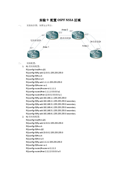
实验9 配置OSPF NSSA区域一、实验拓扑图,如图1.1所示:二、初始配置:1.R1的初始配置:R1(config-line)#int s2/1R1(config-if)#ip add 12.0.0.1 255.255.255.0R1(config-if)#no shR1(config-if)#int lo 0R1(config-if)#ip add 1.1.1.1 255.255.255.0R1(config-if)#router os 1R1(config-router)#router-id 1.1.1.1R1(config-router)#net 1.1.1.1 0.0.0.0 a1R1(config-router)#net 12.0.0.1 0.0.0.0 a 1R1(config-if)#ip add 192.168.1.1 255.255.255.0R1(config-if)#ip add 192.168.2.1 255.255.255.0 secondaryR1(config-if)#ip add 192.168.3.1 255.255.255.0 secondaryR1(config-if)#ip add 192.168.4.1 255.255.255.0 secondaryR1(config-if)#ip add 192.168.5.1 255.255.255.0 secondaryR1(config-if)#ip add 192.168.6.1 255.255.255.0 secondary2.R2的初始配置:R2(config-line)#int s2/1R2(config-if)#ip add 12.0.0.2 255.255.255.0R2(config-if)#no shR2(config-if)#int s2/2R2(config-if)#ip add 23.0.0.2 255.255.255.0R2(config-if)#no shR2(config-if)#int lo 0R2(config-if)#ip add 2.2.2.2 255.255.255.0R2(config-if)#router os 1R2(config-router)#router-id 2.2.2.2R2(config-router)#net 2.2.2.2 0.0.0.0 a 0R2(config-router)#net 12.0.0.2 0.0.0.0 a 1R2(config-router)#net 23.0.0.2 0.0.0.0 a 03.R3的初始配置:R3(config-line)#int s2/1R3(config-if)#ip add 23.0.0.3 255.255.255.0R3(config-if)#no shR3(config-if)#int s2/2R3(config-if)#ip add 34.0.0.3 255.255.255.0R3(config-if)#no shR3(config-if)#int lo 0R3(config-if)#ip add 3.3.3.3 255.255.255.0R3(config-if)#router os 1R3(config-router)#router-id 3.3.3.3R3(config-router)#net 3.3.3.3 0.0.0.0 a 0R3(config-router)#net 23.0.0.3 0.0.0.0 a 0R3(config-router)#net 34.0.0.3 0.0.0.0 a 24.R4的初始配置:R4(config-line)#int s2/1R4(config-if)#ip add 34.0.0.4 255.255.255.0R4(config-if)#no shR4(config-if)#int lo 0R4(config-if)#ip add 4.4.4.4 255.255.255.0R4(config-if)#router os 1R4(config-router)#router-id 4.4.4.4R4(config-router)#net 4.4.4.4 0.0.0.0 a2R4(config-router)#net 34.0.0.4 0.0.0.0 a 25.将Area 1配置为NSSA区域R1(config-if)#router os 1R1(config-router)#area 1 nssaR2(config-if)#router os 1R2(config-router)#area 1 nssa6.在R1上重分布直连路由:R1(config-router)#redistribute connected subnets三、实验调试1.在R1上查看OSPF数据库R1(config-router)#do sh ip os daOSPF Router with ID (1.1.1.1) (Process ID 1)Router Link States (Area 1)Link ID ADV Router Age Seq# Checksum Link count1.1.1.1 1.1.1.1 353 0x80000006 0x0097C1 32.2.2.2 2.2.2.2 802 0x80000005 0x00FB6D 2Summary Net Link States (Area 1)Link ID ADV Router Age Seq# Checksum2.2.2.2 2.2.2.2 808 0x80000002 0x009E863.3.3.3 2.2.2.2 808 0x80000002 0x00F2ED4.4.4.4 2.2.2.2 808 0x80000002 0x00475523.0.0.0 2.2.2.2 808 0x80000002 0x00478F34.0.0.0 2.2.2.2 808 0x80000002 0x003A51Type-7 AS External Link States (Area 1)Link ID ADV Router Age Seq# Checksum Tag 192.168.1.0 1.1.1.1 353 0x80000001 0x00AA79 0 192.168.2.0 1.1.1.1 353 0x80000001 0x009F83 0192.168.3.0 1.1.1.1 353 0x80000001 0x00948D 0 192.168.4.0 1.1.1.1 354 0x80000001 0x008997 0 192.168.5.0 1.1.1.1 354 0x80000001 0x007EA1 0 192.168.6.0 1.1.1.1 354 0x80000001 0x0073AB 0 //以上输出说明,R1上已经有了Type7的LSA2.查看R2的路由表数据库//查看R2的路由表R2(config-router)#do sh ip routCodes: C - connected, S - static, R - RIP, M - mobile, B - BGPD - EIGRP, EX - EIGRP external, O - OSPF, IA - OSPF inter areaN1 - OSPF NSSA external type 1, N2 - OSPF NSSA external type 2E1 - OSPF external type 1, E2 - OSPF external type 2i - IS-IS, su - IS-IS summary, L1 - IS-IS level-1, L2 - IS-IS level-2ia - IS-IS inter area, * - candidate default, U - per-user static routeo - ODR, P - periodic downloaded static routeGateway of last resort is not set34.0.0.0/24 is subnetted, 1 subnetsO IA 34.0.0.0 [110/128] via 23.0.0.3, 00:00:08, Serial2/21.0.0.0/32 is subnetted, 1 subnetsO 1.1.1.1 [110/65] via 12.0.0.1, 00:00:08, Serial2/12.0.0.0/24 is subnetted, 1 subnetsC 2.2.2.0 is directly connected, Loopback03.0.0.0/32 is subnetted, 1 subnetsO 3.3.3.3 [110/65] via 23.0.0.3, 00:07:42, Serial2/24.0.0.0/32 is subnetted, 1 subnetsO IA 4.4.4.4 [110/129] via 23.0.0.3, 00:00:08, Serial2/223.0.0.0/24 is subnetted, 1 subnetsC 23.0.0.0 is directly connected, Serial2/2O N2 192.168.4.0/24 [110/20] via 12.0.0.1, 00:00:08, Serial2/1O N2 192.168.5.0/24 [110/20] via 12.0.0.1, 00:00:10, Serial2/1O N2 192.168.6.0/24 [110/20] via 12.0.0.1, 00:00:10, Serial2/112.0.0.0/24 is subnetted, 1 subnetsC 12.0.0.0 is directly connected, Serial2/1O N2 192.168.1.0/24 [110/20] via 12.0.0.1, 00:00:10, Serial2/1O N2 192.168.2.0/24 [110/20] via 12.0.0.1, 00:00:10, Serial2/1O N2 192.168.3.0/24 [110/20] via 12.0.0.1, 00:00:10, Serial2/1//查看R2的OSPF数据库R2(config-router)#do sh ip os daOSPF Router with ID (2.2.2.2) (Process ID 1)Router Link States (Area 0)Link ID ADV Router Age Seq# Checksum Link count2.2.2.2 2.2.2.2 1310 0x80000005 0x00A88F 33.3.3.3 3.3.3.3 525 0x80000004 0x00CC63 3Summary Net Link States (Area 0)Link ID ADV Router Age Seq# Checksum1.1.1.12.2.2.2 1296 0x80000001 0x00AB444.4.4.4 3.3.3.3 525 0x80000002 0x0001DD12.0.0.0 2.2.2.2 543 0x80000002 0x0031B634.0.0.0 3.3.3.3 525 0x80000002 0x00F3D9Summary ASB Link States (Area 0)Link ID ADV Router Age Seq# Checksum4.4.4.4 3.3.3.3 525 0x80000002 0x00E8F5Router Link States (Area 1)Link ID ADV Router Age Seq# Checksum Link count1.1.1.1 1.1.1.1 858 0x80000006 0x0097C1 32.2.2.2 2.2.2.2 1306 0x80000005 0x00FB6D 2Summary Net Link States (Area 1)Link ID ADV Router Age Seq# Checksum2.2.2.2 2.2.2.2 1312 0x80000002 0x009E863.3.3.3 2.2.2.2 1312 0x80000002 0x00F2ED4.4.4.4 2.2.2.2 1312 0x80000002 0x004755 23.0.0.0 2.2.2.2 1312 0x80000002 0x00478F 34.0.0.0 2.2.2.2 1312 0x80000002 0x003A51Type-7 AS External Link States (Area 1)Link ID ADV Router Age Seq# Checksum Tag 192.168.1.0 1.1.1.1 859 0x80000001 0x00AA79 0 192.168.2.0 1.1.1.1 859 0x80000001 0x009F83 0 192.168.3.0 1.1.1.1 859 0x80000001 0x00948D 0 192.168.4.0 1.1.1.1 859 0x80000001 0x008997 0 192.168.5.0 1.1.1.1 859 0x80000001 0x007EA1 0 192.168.6.0 1.1.1.1 859 0x80000001 0x0073AB 0Type-5 AS External Link StatesLink ID ADV Router Age Seq# Checksum Tag 192.168.1.0 2.2.2.2 852 0x80000001 0x002109 0 192.168.2.0 2.2.2.2 853 0x80000001 0x001613 0 192.168.3.0 2.2.2.2 853 0x80000001 0x000B1D 0 192.168.4.0 2.2.2.2 853 0x80000001 0x00FF27 0 192.168.5.0 2.2.2.2 853 0x80000001 0x00F431 0 192.168.6.0 2.2.2.2 853 0x80000001 0x00E93B 0。
实验10 OSPF多区域基本配置
实验名称OSPF多区域基本配置。
实验目的掌握OSPF基本配置技术。
实现功能构建OSPF多个区域连在骨干网络上。
实验设备锐捷R1726路由器2台,网线2根,V35线缆1对,计算机2台。
背景描述一个公司总部和销售公司分处在两个地方,现为了搭建公司的OA系统,需要通过OSPF协议将两地的网络连在一起。
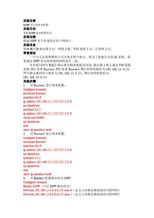
本实验以两台R2624路由器为例来模拟该环境,路由器1和2通过V35线缆连接。
PC1连着Router1,PC2连着Router2.PC1的网络地址为192.168.11.0/24,两个路由器的串口地址为192.168.12.0/24,PC2的网络地址为192.168.13.0/24.实验步骤1.对Router1进行基本配置:configure terminalhostname Router1interface fa1/0ip address 192.168.11.1 255.255.255.0no shutdowninterface S1/2ip address 192.168.12.1 255.255.255.0clock rate 64000no shutdownexitshow ip interface brief2.对Router2进行基本配置:configure terminalhostname Router2interface fa1/0ip address 192.168.13.1 255.255.255.0no shutdowninterface S1/2ip address 192.168.12.2 255.255.255.0no shutdownexitshow ip interface brief3.对Router1配置路由协议OSPF:Configure terminalRouter OSPF(开启OSPF路由协议)Network 192.168.11.0 0.0.0.255 area 0(定义与本路由器相连的关联网络)Network 192.168.12.0 0.0.0.255 area 1(定义与本路由器相连的关联网络)EndShow ip nei(显示路由表)4.对Router2配置路由协议rip2:Configure terminalRouter OSPF(开启OSPF路由协议)Network 192.168.13.0 0.0.0.255 area 2(定义与本路由器相连的关联网络)Network 192.168.12.0 0.0.0.255 area 1(定义与本路由器相连的关联网络)EndShow ip nei(显示路由表)5.测试网络的连通性,将两台计算机的IP地址设为所属网段的地址,网关设为所连路由器的以太网口的地址。
实验 11.6.1:基本 OSPF 配置实验
实验 11.6.1:基本 OSPF 配置实验学习目标完成本实验后,您将能够:•根据拓扑图完成网络电缆连接•删除路由器启动配置并将其重新加载到默认状态•在路由器上执行基本配置任务•配置并激活接口•在所有路由器上配置 OSPF 路由•配置 OSPF 路由器 ID•使用 show 命令检验 OSPF 路由•配置静态默认路由•向 OSPF 邻居传播默认路由•配置 OSPF Hello 计时器和 Dead 计时器•在多路访问网络上配置 OSPF•配置 OSPF 优先级•理解 OSPF 选举过程•记录 OSPF 配置场景在本实验练习中有两个独立的场景。
在第一个场景中,您将使用场景 A 中的拓扑图所示的网络学习如何配置 OSPF 路由协议。
该网络中的各个网段使用 VLSM 划分了子网。
OSPF 是一种无类路由协议,可用于在路由更新中提供子网掩码信息。
这将使 VLSM 子网信息可传播到整个网络。
在第二个场景中,您将学习在多路访问网络中配置 OSPF。
您还将学习使用 OSPF 选举过程来确定指定路由器 (DR)、后备指定路由器 (BDR) 和 DRother 状态。
场景 A:基本 OSPF 配置拓扑图地址表设备接口IP 地址子网掩码默认网关Fa0/0 172.16.1.17 255.255.255.240 不适用R1S0/0/0 192.168.10.1 255.255.255.252 不适用S0/0/1 192.168.10.5 255.255.255.252 不适用Fa0/0 10.10.10.1 255.255.255.0 不适用R2S0/0/0 192.168.10.2 255.255.255.252 不适用S0/0/1 192.168.10.9 255.255.255.252 不适用Fa0/0 172.16.1.33 255.255.255.248 不适用R3S0/0/0 192.168.10.6 255.255.255.252 不适用S0/0/1 192.168.10.10 255.255.255.252 不适用PC1 网卡172.16.1.20 255.255.255.240 172.16.1.17 PC2 网卡10.10.10.10 255.255.255.0 10.10.10.1 PC3 网卡172.16.1.35 255.255.255.248 172.16.1.33任务 1:准备网络。
ensp模拟器之ospf实验

ensp模拟器之ospf实验OSPF(开放最短路径优先)是一种常用的链路状态路由协议,用于在互联网络中实现路由器之间的通信。
它基于Dijkstra算法来计算最短路径,并使用LSA(链路状态广播)协议来在网络中传播状态信息。
在该模拟实验中,我们将使用一个OSPF模拟器来演示OSPF协议的工作原理。
首先,我们需要安装一个OSPF模拟器,该模拟器提供了一个虚拟网络环境,可以模拟多个路由器之间的通信。
我们可以使用Cisco Packet Tracer或GNS3等模拟器。
接下来,我们将创建一个包含多个路由器的拓扑图。
在该拓扑图中,每个路由器将代表一个网络节点,并且它们之间通过链路进行连接。
我们可以选择不同的路由器型号和链路速率来模拟真实世界的网络环境。
然后,我们需要对每个路由器进行配置。
配置包括设置路由器的IP 地址、启用OSPF协议、设置区域和配置链路权重等。
每个路由器将作为OSPF的邻居,它们将通过OSPF协议交换状态信息,并计算最短路径。
在这个过程中,可以使用OSPF的一些特性,如区域划分、路径筛选和路由重分发等。
完成配置后,我们可以启动路由器,并观察OSPF协议的工作。
通过在路由器上执行相应的OSPF命令,我们可以查看当前的路由表、OSPF邻居列表和链路状态数据库等信息。
同时,我们还可以进行一些操作,如手动设置链路权重、增加或删除网络、设置路由聚合等。
在实验过程中,我们可以模拟一些故障情况,如链路断开、路由器故障等。
这将导致OSPF重新计算最短路径,并选择备用路径进行通信。
通过这些操作,我们可以观察到OSPF的动态性和可靠性。
最后,我们需要对实验结果进行分析和总结。
我们可以比较不同配置下的路由表和路径选择,评估OSPF协议的性能和可扩展性。
同时,我们还可以探讨OSPF在实际网络中的应用,如大规模网络中的区域设计、网络收敛和负载均衡等。
总结起来,通过该OSPF模拟实验,我们可以深入了解OSPF协议的工作原理和特性。
- 1、下载文档前请自行甄别文档内容的完整性,平台不提供额外的编辑、内容补充、找答案等附加服务。
- 2、"仅部分预览"的文档,不可在线预览部分如存在完整性等问题,可反馈申请退款(可完整预览的文档不适用该条件!)。
- 3、如文档侵犯您的权益,请联系客服反馈,我们会尽快为您处理(人工客服工作时间:9:00-18:30)。
OSPF 讲义一.实验显示邻居和邻接过程的建立此实验(lab2)只是启用r1 ,r2 来验证邻接和邻居关系的建立,首先给r1和r2配置 r1>enr1#conf tr1(config)#interface loopback 0//创建环回口r1(config-if)#ip address 1.1.1.1 255.255.255.0r1(config-if)#exitr1(config)#int s0/0r1(config-if)#ip add 12.1.1.1 255.255.255.252//给路由器R1 的S0接口配IP 地址 r1(config-if)#exitr1(config)#router ospf 100r1(config-router)#router-id 1.1.1.1(1.1.1.1随便写)r1(config-router)#network 1.1.1.0 0.0.0.255 area 0 // 宣告loopback 地址r1(config-router)#net 12.1.1.0 0.0.0.3 area 0//宣告互联地址 0.0.0.3 反掩码 r1(config-router)#int s 0/0r1(config-if)#shut 出现: Interface Serial0/0, changed state to administratively down Line protocol on Interface Serial0/0, changed state to down把s0/0接口先DOWN 了,关闭的目的是让R1和R2之间不能够进行通信,他们之间不能学习。
因为我们是要观察OSPF 建立邻接关系的过程,然后再把他们启用起来,让大家看启用过程下面是对R2路由器的配置r2>enr2#conf tr2(config)#interface loopback 0//创建环回口r2(config-if)#ip address 2.2.2.2 255.255.255.0r2(config-if)#exitr2(config)#int s0/0r2(config)#no shutr2(config-if)#ip add 12.1.1.2 255.255.255.252//给路由器R1 的S0接口配IP 地址Loopback0Loopback 1.1.1.11 子网掩码:255.255.255.252r2(config-if)#exitr2(config)#router ospf 100r2(config-router)#router-id 2.2.2.2r2(config-router)#network 2.2.2.0 0.0.0.255 area 0r2(config-router)#network 12.1.1.0 0.0.0.3 area 0r2(config-router)#endr2#debug ip ospf events//打开调试信息页面出现:OSPF enents debugging is on ,它能反映OSPF建立邻接关系的各个阶段,他们的协商过程。
但是对于包类型反映的不是很精准。
loading状态通过event过程看的不是很清楚。
所以把这条命令和下条命令结合起来看r2#debug ip ospf pack//单独打开此命令,只能看到何时收到了什么包,不显示发送在R1中同样使用这两条debug命令,在此用do是因为模式不一样,目前是接口配置模式可以加上dor1(config-if)#do debug ip ospf eventsr1(config-if)#do debug ip ospf pack接下来看结果在R1中r1(config-if)#no shut// 输入该命令后就建立了,等待看结果r1(config-if)#end当出现serial0/0 from loading to full,loading done //这个FULL状态,就算调试结束,然后关闭调试信息r1#no debug ip ospf evenr1#no debug ip ospf packr2#no debug ip ospf evenr2#no debug ip ospf pack 接下来看中间的调试信息调试:r1#show ip routeR1显示路由信息出现:1.0.0.0/24 is subnetted, 1 subnetsC 1.1.1.0 is directly connected, Loopback02.0.0.0/32 is subnetted, 1 subnetsO 2.2.2.2 [110/65] via 12.1.1.2, 00:07:00, Serial0/012.0.0.0/30 is subnetted, 1 subnetsC 12.1.1.0 is directly connected, Serial0/0R2显示路由信息出现:1.0.0.0/32 is subnetted, 1 subnetsO 1.1.1.1 [110/65] via 12.1.1.1, 00:11:00, Serial0/02.0.0.0/24 is subnetted, 1 subnetsC 2.2.2.0 is directly connected, Loopback012.0.0.0/30 is subnetted, 1 subnetsC 12.1.1.0 is directly connected, Serial0/0r1#show ip ospf interfacer1#show ip ospf neighbor显示:Neighbor ID Pri State Dead Time Address Interface2.2.2.2 0 FULL/ - 00:00:39 12.1.1.2 Serial0/0二.对单区域的OSPF配置加以扩展(lab3)1.路由器router id的配置CCNA阶段:单区域的router id的配置,启动OSPF以后看一下有没有loopback地址,如果有,就比较loopback地址,如果没有就找接口地址,总之就是参与OSPF进程里面的活动的接口地址,哪个高,做为该路由器的router id在NP中学会去指定一个router id,虽然学会了,但是大家不能去这样做,仍然建议大家使用loopback地址去确定路由器的router id查看OSPF的router id:输入:r1#show ip ospf提示:routing process"osfp 100" with ID 1.1.1.1 //进程号是100路由器的router id 是1.1.1.1,配置过程:先进入到OSPF里面去r1#conf tr1(config)#router ospf 100//进入100进程r1(config-router)#router-id 1.1.1.4 //修改router-id为一个IP地址显示:Reload or use "clear ip ospf process" command, for this to take effectr1(config-router)#end查看:r1#show ip ospf //发现还是没有变routing process"osfp 100" with ID 1.1.1.1,因为重启路由器才能发生作用:reload or use "clear ip ospf process"command,for this to take effect所以我们就键入该命令输入:r1#clea ip ospf process提示:reset all ospf processes?[no]:yr1#show ip ospf //发现变化了:routing process"osfp 100" with ID 1.1.1.4下面我们把它NO掉我们先看一下r1#show run 显示:router-id 1.1.1.4下面把他NO掉:r1#conf tr1(config)#router ospf 100r1(config-router)#no router-id 1.1.1.4r1(config-router)#endr1#clea ip ospf process提示:reset all ospf processes?[no]:yr1#end再来看r1#show ip ospf 发现变回去了2.环回接口:最大特点永远不会DOWN,从物理意义上讲,还回口不存在,所以不会出现故障,虚拟出来的虚链路。
再稳定的电路也不能保证不出故障。
下面是查看环回口的命令先打开接口(lab3)r1#conf tr1(config)#int lo0r1(config-if)#end查看环回口命令:r1#show int lo 0显示:loopback0 is up, line protocol is upHardware is loopback3.下面讲修改度量值,如何修改度量值(默认成本)?100M除以该接口的实际带宽,所以对于百兆的度量值是1,对于10M的链路就是10r1#conf tr1(config)#int s 0/0r1(config-if)#ip ospf cost ?提示:<1-65535> cost配置cost=1,链路是100M会不会有65535出现?如果配置cost=65535,100M/65535=0.001525M,说明你的链路是0.001525M也就是大概1K,有没有1K的链路呢(此时单位还是位)?没有!!所以不会有65535。
另外说明,运营商在偷换一个概念,虽然ADSL号称1M,但是单位是位bit,要除以8才得到字节,了不起就是100多K,达到100多K实际以及很好了。
所以:cost的值越大,说明实际带宽越低,当cost=65535,说明实际带宽只有1K修改:r1(config-if)#ip ospf cost :此命令使用起来不方便,后期维护也比较麻烦所以使用:打入:r1(config-if)#bandwidth ?显示:<1-10000000> bandwidth in kilobits //表示单位是K打入命令:r1(config-if)#bandwidth 64 这样运用到工程里面就知道了接口实际带宽是多大,而且OSPF在参与度量值进行运算的时候会使用bandwidth所指定的带宽情况一:如果我不配OSPF 的cost 也不配bandwidth。