分动器说明书
起重机分动器使用说明书
起重机分动器使用说明书一、产品介绍起重机分动器是一种用于连接起重机和工作平台的装置,它能够实现起重机的左右移动和转向。
该产品采用高强度材料制造,具有结构紧凑、操作简便、安全可靠等特点。
二、使用方法1、安装:将分动器本体安装在起重机上,并与工作平台相连。
连接时应按照说明书要求进行操作,确保连接牢固可靠。
2、操作:启动起重机电源后,通过控制器对分动器进行操作。
控制器上设有左右移动和转向按钮,分别对应分动器的左右移动和转向功能。
操作时应注意安全,避免发生意外事故。
3、维护:定期检查分动器的各部件是否正常运转,如有异常情况应及时处理。
同时,应保持分动器表面清洁,避免灰尘和杂物进入影响使用效果。
三、注意事项1、在操作前应仔细阅读说明书,了解产品的使用方法和注意事项。
2、在操作过程中应注意安全,避免发生意外事故。
如发现任何异常情况应及时停止操作并排除故障。
3、在维护时应注意保护设备表面,避免划伤或损坏。
同时,应定期更换润滑油脂等易损件,保证设备的正常运转。
四、常见问题及解决方法1、无法移动或转向:检查控制器是否正常工作,是否有电流输出;检查分动器连接是否牢固可靠;检查电机是否正常运转。
如有问题应及时排除故障。
2、噪音过大:检查分动器内部是否有异物或损坏部件;检查电机是否正常运转;检查减速器是否需要更换。
如有问题应及时处理。
3、制动失灵:检查制动器是否正常工作;检查制动片是否磨损严重;检查液压系统是否正常。
如有问题应及时排除故障。
五、总结起重机分动器是一种重要的起重设备配件,它的正确使用和维护对于提高工作效率和保障作业安全具有重要意义。
在使用过程中应注意遵守相关法律法规和安全规定,确保设备的正常运转和人员的生命财产安全。
Fabco TC-200 分动箱零件手册说明书

Fabco TC-200 Transfer C ase P arts ManualPro Gear Fabco TC-200 Transfer C ase Parts Manual t o assist in identifying your Fabco unit.If you need any assistance identifying the correct transfer case unit for your truck and equipment, contact your Fabco replacement part specialists at Pro Gear and Transmission.Pro Gear Transmission has same day shipping and 1000’s of products in stock and ready to ship internationally for your next project.For parts or service contact the Fabco specialists at Pro Gear & Transmission, Inc.1 (877) 776-4600(407) 872-1901******************AUTOMOTIVE CORPORATIONFABCO TC-200TRANSFER CASEPARTS MANUALPart Number873-0042-001Fabco Automotive Corporation, Livermore, CA9. ILLUSTRATED PARTS MANUALTABLE OF CONTENTSPAGE P.1 Introduction (33)P.2 Input Shaft Parts (34)P.3 Intermediate Shaft Parts (36)P.4 Front Output Shaft Parts (38)P.5 Rear Output Shaft Parts (40)P.6 Front Drive Shift Parts (42)P.7 High/Low Range Shift Parts (44)P.8 Rear Drive Shift Parts (46)P.9 Housing Parts (48)P.1 INTRODUCTIONTO USE THIS ILLUSTRATED PARTS SECTION:1. Refer to the figure which illustrates the needed part.2. Find the required part and note the item number.3. Locate the item number in the parts list section for the required part number, description, andquantity used.NOTE: When ordering parts, specify the transfer case model number, the serial number and any other information that is on the Fabco nameplate located on the transfer case housing. The part numbers contained in this manual were in effect at the time the manual was approved for printing and are subject to change without notice or liability. Fabco Automotive Corporation reserves the right to change parts at anytime.USE ONLY GENUINE FABCO PARTSP.2 TC-200 INPUT SHAFT PARTSSee Figure P.2FOOT ITEM PART NO. DESCRIPTION QTY NOTE1 688-0694 Locknut, 1 1/2-12 12 927-0775-005 Washer 13 732-0396 Oil Seal 14 233-0537 Bearing Cup 15 233-0558 Bearing Cone 16 432-0667 Gear 17 966-0329 Woodruff Key 18 776-0269 Shaft 19 432-0669 Clutch Collar Gear 110 233-0542 Bearing Cone 211 233-0539 Bearing Cup 212 756-0257-001 Bearing Spacer Ring,.352 Thick 1756-0257-002 Bearing Spacer Ring,.355 Thick 1756-0257-003 Bearing Spacer Ring,.358 Thick 1756-0257-004 Bearing Spacer Ring,.361 Thick 1756-0257-005 Bearing Spacer Ring,.348 Thick 1756-0257-006 Bearing Spacer Ring,.349 Thick 1756-0257-007 Bearing Spacer Ring,.350 Thick 1756-0257-008 Bearing Spacer Ring,.351 Thick 1756-0257-009 Bearing Spacer Ring,.353 Thick 1756-0257-010 Bearing Spacer Ring,.354 Thick 1756-0257-011 Bearing Spacer Ring,.356 Thick 1756-0257-012 Bearing Spacer Ring,.357 Thick 1756-0257-013 Bearing Spacer Ring,.359 Thick 1756-0257-014 Bearing Spacer Ring,.360 Thick 113 432-0665 Gear 114 756-0259 Spacer Ring 115 233-0443 Bearing Cone 116 233-0444 Bearing Cup 117 756-0258 Spacer Ring 118 688-0645 Bearing Locknut 1219 744-0359-001 Shim, .002 Thick Red A/R744-0359-002 Shim, .005 Thick Blue A/R 2744-0359-003 Shim, .015 Thick Pink A/R 2744-0359-004 Shim, .030 Thick Coral A/R 220 235-0647-001 Cap 1 3235-0647-002 Cap 1 421 265-0238 Cap Screw, 7/16-14 x 1 1/4 6FOOTNOTES:1. Select one spacer ring. See service manual.2. See service manual.3. Models without optional lubrication pump.4. Models equipped with optional lubrication pump.P.300 IN T ER M E D I A TE SHAFT PARTS See Fig u re P.3FOOT ITEM PART NO.DE S CRIP T IO N QTY NOTE 1688-0645Bear i ng Locknut 12756-0258Spacer Ring 13233-0444Bear i ng Cup 14233-0443Bear i ng Cone 15233-0542Bear i ng Cone 26233-0539Bear i ng Cup 27432-0668Gear 18756-0257-001Bear i ng Spacer Ring,.352 Thick 1756- 0257- 002Bear i ng Spacer Ring,.355 Thick 1756- 0257- 003Bear i ng Spacer Ring,.358 Thick 1756- 0257- 004Bear i ng Spacer Ring,.361 Thick 1756-0257- 005Bear i ng Spacer Ring,.348 Thick 1756-0257- 006Bear i ng Spacer Ring,.349 Thick 1756-0257- 007Bear i ng Spacer Ring,.350 Thick 1756-0257- 008Bear i ng Spacer Ring,.351 Thick 1756-0257- 009Bear i ng Spacer Ring,.353 Thick 1756-0257- 010Bear i ng Spacer Ring,.354 Thick 1756-0257- 011Bear i ng Spacer Ring,.356 Thick 1756-0257- 012Bear i ng Spacer Ring,.357 Thick 1756-0257- 013Bear i ng Spacer Ring,.359 Thick 1756-0257- 014Bear i ng Spacer Ring,.360 Thick 19432-0669Clutch Col l ar Gear 110776-0262Shaft 111966-0328Wood r uff Key 112432-0666Gear 113233-0379Bear i ng Cone 114233-0378Bear i ng Cup 115744-0362-001Shim, .002 Thick Red A/R 2744- 0362- 002Shim, .005 Thick Blue A/R 2744- 0362- 003Shim, .015 Thick Pink A/R 2744- 0362- 004Shim, .030 Thick Coral A/R 216235-0653Cap 117427-0468Gasket 118235-0633Cap 1319927-0299Lockwasher, 5/166320265-0355Cap Screw, 5/16- 24 x 3/46321265-0238Cap Screw, 7/16- 14 x 1 1/46TES:1.ect one spacer ring. See serv i ce man u al.2.See serv i ce man u al.3.Parts not used for TC- 200’s with lu b ri atin pump. See lu b ri ion sys t em parts.P.3 TC- 200 INTER TE SHAFT PARTSSee Figure P.3FOOTITEM PART NO. NQTY NOTE1688-0645ng Locknut12 756-0258 Spacer Ring 13 233-0444 ng Cup 1 4 233-0443 ng Cone 15 233-0542 ng Cone 26 233-0539 ng Cup 27 432-0668 Gear18756-0257-001 ng Spacer Ring,.352 Thick 1 02 ng Spacer Ring,.355 Thick 1 03 ng Spacer Ring,.358 Thick 1 04 ng Spacer Ring,.361 Thick 1 05 ng Spacer Ring,.348 Thick 1 06 ng Spacer Ring,.349 Thick 1 07 ng Spacer Ring,.350 Thick 1 08 ng Spacer Ring,.351 Thick 1 09 ng Spacer Ring,.353 Thick 1 10 ng Spacer Ring,.354 Thick 1 11 ng Spacer Ring,.356 Thick 1 12 ng Spacer Ring,.357 Thick 1 13 ng Spacer Ring,.359 Thick 1 14 ng Spacer Ring,.360 Thick 19432-0669 Clutch Collar Gear 110 776-0262 Shaft1 11 966-0328 uff Key 1 12 432-0666 Gear1 13 233-0379 ng Cone 1 14 233-0378 ng Cup1 15744-0362-001 Shim, .002 Thick Red A/R 202 Shim, .005 Thick Blue A/R 2 03 Shim, .015 Thick Pink A/R 2 04 Shim, .030 Thick Coral A/R 216235-0653 Cap 1 17 427-0468 Gasket 1 18 235-0633 Cap1 319 927-0299 Lockwasher, 5/16 6 3 20 265-0355 Cap Screw, 5/16-24 x 3/4 6 321265-0238Cap Screw, 7/16-14 x 1 1/46FO O T N O TES:1. Se l ect one spacer ring. See service manual.2.See service manual.3. Parts not used for TC-200’s with lubri c atin pump. See lubric a t ion system parts.P.4 TC-200 FRONT OUTPUT SHAFT PARTSSee Figure P.4FOOT ITEM PART NO. DESCRIPTION QTY NOTE1 688-0694 Locknut, 1 1/2-12 12 927-0775-005 Washer 13 732-0396 Oil Seal 14 233-0272 Bearing Cup 15 233-0559 Bearing Cone 16 776-0272 Shaft 17 432-0669 Clutch Collar Gear 18 233-0542 Bearing Cone 29 233-0539 Bearing Cup 210 756-0257-001 Bearing Spacer Ring,.352 Thick 1756-0257-002 Bearing Spacer Ring,.355 Thick 1756-0257-003 Bearing Spacer Ring,.358 Thick 1756-0257-004 Bearing Spacer Ring,.361 Thick 1756-0257-005 Bearing Spacer Ring,.348 Thick 1756-0257-006 Bearing Spacer Ring,.349 Thick 1756-0257-007 Bearing Spacer Ring,.350 Thick 1756-0257-008 Bearing Spacer Ring,.351 Thick 1756-0257-009 Bearing Spacer Ring,.353 Thick 1756-0257-010 Bearing Spacer Ring,.354 Thick 1756-0257-011 Bearing Spacer Ring,.356 Thick 1756-0257-012 Bearing Spacer Ring,.357 Thick 1756-0257-013 Bearing Spacer Ring,.359 Thick 1756-0257-014 Bearing Spacer Ring,.360 Thick 111 432-0665 Gear 112 756-0259 Spacer Ring 113 233-0443 Bearing Cone 114 233-0444 Bearing Cup 115 756-0258 Spacer Ring 116 688-0645 Bearing Locknut 117 744-0359-001 Shim, .002 Thick Red A/R 2744-0359-002 Shim, .005 Thick Blue A/R 2744-0359-003 Shim, .015 Thick Pink A/R 2744-0359-004 Shim, .030 Thick Coral A/R 218 235-0649 Cap 119 265-0238 Cap Screw, 7/16-14 x 1 1/4 6FOOTNOTES:1. Select one spacer ring. See service manual.2. See service manual.P.5 TC-200 REAR OUTPUT SHAFT PARTSSee Figure P.5FOOT ITEM PART NO. DESCRIPTION QTY NOTE1 233-0272 Bearing Cup 12 233-0543 Bearing Cone 13 776-0273 Shaft 14 432-0669 Clutch Collar Gear 15 233-0542 Bearing Cone 26 233-0539 Bearing Cup 27 756-0257-001 Bearing Spacer Ring,.352 Thick 1756-0257-002 Bearing Spacer Ring,.355 Thick 1756-0257-003 Bearing Spacer Ring,.358 Thick 1756-0257-004 Bearing Spacer Ring,.361 Thick 1756-0257-005 Bearing Spacer Ring,.348 Thick 1756-0257-006 Bearing Spacer Ring,.349 Thick 1756-0257-007 Bearing Spacer Ring,.350 Thick 1756-0257-008 Bearing Spacer Ring,.351 Thick 1756-0257-009 Bearing Spacer Ring,.353 Thick 1756-0257-010 Bearing Spacer Ring,.354 Thick 1756-0257-011 Bearing Spacer Ring,.356 Thick 1756-0257-012 Bearing Spacer Ring,.357 Thick 1756-0257-013 Bearing Spacer Ring,.359 Thick 1756-0257-014 Bearing Spacer Ring,.360 Thick 18 432-0665 Gear 19 756-0262 Spacer Ring 110 233-0493 Bearing Cone 111 233-0544 Bearing Cup 112 756-0263 Spacer Ring 113 432-0678 Gear, Speedometer Sensor 114 744-0278 Shim, .030 Thick Coral A/R 2744-0279 Shim, .015 Thick Pink A/R 2744-0282 Shim, .005 Thick Blue A/R 2744-0283 Shim, .002 Thick Red A/R 215 237-0629 Carrier 116 732-0396 Oil Seal 117 688-0738 Locknut 118 265-0238 Cap Screw, 7/16-14 x 1 1/4 6FOOTNOTES:1. Select one spacer ring. See service manual.2. See service manual.Pro Gear and Transmission • 906 W. Gore St. Orlando, FL 32805 • 1 (877) 776-4600 / (407) 872-1901P.6 TC-200 FRONT DRIVE SHIFT PARTSSee Figure P.6ITEM PART NO. DESCRIPTION QTY1 265-0386 Cap Screw, 1/4-20 x 3/4 42 235-0634 Cap 13 673-0229 O-Ring 14 688-0464 Locknut, 3/8-24 15 927-0643 Washer 16 675-0326 O-Ring 17 753-0232 Piston 18 339-0223 Felt Strip 19 736-0747 Stop Ring 110 777-0477 Spring 111 782-0288 O-Ring 112 776-1265 Shifter Shaft Assembly 113 927-0427 Copper Washer 114 798-0245 Indicator Switch 115 746-0739 Shift Indicator Pin 1 Pro Gear and Transmission • 906 W. Gore St. Orlando, FL 32805 • 1 (877) 776-4600 / (407) 872-1901P.7 TC-200 HIGH/LOW RANGE SHIFT PARTSSee Figure P.7ITEM PART NO. DESCRIPTION QTY1 758-0328 Expansion Plug 12 776-0267 Shifter Shaft 13 782-0288 O-Ring 14 947-0223 Lockwire 25 724-0222 Set Screw 26 367-0292 Shift Fork 27 675-0224 O-ring 38 884-0224 Adapter Tube 19 883-0887-007 Shift Cylinder Tube 110 777-0534 Spring 111 736-0747 Stop Ring 112 339-0223 Felt Strip 113 753-0232 Piston 114 675-0326 O-Ring 115 927-0643 Washer 116 688-0464 Locknut, 3/8-24 117 235-0352 Cap 118 283-0235 Cap Screw, 1/4-20 x 4 1/4 4 Pro Gear and Transmission • 906 W. Gore St. Orlando, FL 32805 • 1 (877) 776-4600 / (407) 872-1901P.8 TC-200 REAR DRIVE SHIFT PARTSSee Figure P.8ITEM PART NO. DESCRIPTION QTY1 758-0328 Expansion Plug 12 776-0266 Shifter Shaft 13 782-0288 O-Ring 14 947-0223 Lockwire 15 724-0222 Set Screw 16 367-0292 Shift Fork 17 675-0224 O-Ring 38 883-0482 Adapter Tube 19 883-0887-016 Shift Cylinder Tube 110 777-0477 Spring 111 736-0747 Stop Ring 112 339-0223 Felt Strip 113 753-0232 Piston 114 675-0326 O-Ring 115 927-0643 Washer 116 688-0464 Locknut, 3/8-24 117 235-0352 Cap 118 265-0769 Cap Screw, 1/4-20 x 3 3/4 4 Pro Gear and Transmission • 906 W. Gore St. Orlando, FL 32805 • 1 (877) 776-4600 / (407) 872-1901P.9 TC-200 HOUSING PARTSSee Figure P.9FOOT ITEM PART NO. DESCRIPTION QTY NOTE1 478-0282 Housing, Front 12 478-0284 Housing, Rear 13 265-0535 Bolt, 1/2-13 x 4, Grade 5, Hex Head 34 927-0722 Washer, 1/2" 225 287-0276 Bushing 2 16 427-0539 Gasket 17 758-0232 Plug, 1/4 NPT 28 836-0223 Vent, Breather 19 357-0678 Elbow 110 626-0228 Serial Number Plate 111 724-0276 Drive Screw 212 758-0229 Plug, 3/4 NPT 213 265-0979 Bolt, 1/2-13 x 3 1/2, Grade 5, Hex Head 1814 758-0274 Magnetic Drain Plug, 3/4 NPT 2 215 758-0375 Plug, 3/8 NPT 1FOOTNOTES:1. Upper plug not used for transfer case with lubricatin pump. See lubricatin system parts.2. Lower rear plug not used for transfer case with lubrication pump. See lubrication system parts.Pro Gear and Transmission • 906 W. Gore St. Orlando, FL 32805 • 1 (877) 776-4600 / (407) 872-1901。
电动分离机使用说明书

电动分离机使用说明书使用说明书一、产品简介电动分离机是一种用于分离混合物中的固体和液体的设备。
它通过旋转力将物料分离成两个或多个组分,并实现固体和液体的分离。
本使用说明书将为您介绍电动分离机的结构、使用方法以及注意事项。
二、产品结构电动分离机主体包括以下部分:1. 机座:为整个设备的基础支撑,保证设备的稳定性;2. 机壳:覆盖在机座之上,起到保护内部零部件的作用;3. 主电机:提供动力,带动分离机内部的旋转部件;4. 分离鼓:设备的关键部分,旋转时完成物料的分离;5. 进料管道:用于物料的输入;6. 出料口:用于分离后的液体和固体的分别排出;7. 控制面板:用于控制电动分离机的启停、转速等参数。
三、使用方法1. 准备工作:检查电动分离机的电源接线是否正常,机器是否安装稳固,检查机壳是否关闭牢固;2. 启动电机:按下控制面板上的启动按钮,确保电机转速正常;3. 输入物料:将需要分离的混合物通过进料管道输入电动分离机;4. 调整转速:根据物料的性质和分离要求,适当调整电动分离机的转速;5. 分离过程:启动电机后,电动分离机内部的分离鼓开始旋转,物料被分离成固体和液体两个组分;6. 收集分离物料:固体和液体分别从出料口排出,收集并储存。
四、注意事项1. 操作前请认真阅读本使用说明书,并确保掌握正确的使用方法;2. 在操作过程中,应注意个人安全,避免手指或其他物体接触旋转部件;3. 在使用过程中,如发现电动分离机存在异常噪音、异味等现象,请立即停机检查;4. 若长时间不使用电动分离机,请将电源拔掉,以免造成不必要的安全隐患;5. 请勿私自拆卸或修改设备内部结构,如有需要,请联系专业人员进行维修。
请您根据以上内容使用电动分离机,仔细阅读并按照使用说明进行操作。
如有任何疑问或操作中遇到困难,请及时与售后服务部门联系。
祝您使用愉快!。
第三章变速器,第五节分动器1
§3.5分动器一.基本概念1.分动器的作用:用于越野车,使变速器输出的动力分配到各驱动桥。
2.在传动系中的安装布置位置:布置在变速器之后---即变速器输出的动力通过传动轴输入给分动器;分动器再向前桥、后桥(4×4)或其它多个驱动桥(6×6及以上的越野车)分别输出动力。
参见图3-25。
3.分动器的档位设置:一般设高、低2个档。
4.分动器前桥使用:▲好路行驶:不接前桥。
此时前桥为从动桥,可避免功率消耗及轮胎、传动系零件磨损。
只后桥或其它驱动桥驱动。
▲坏路行驶:接前桥。
此时前桥为转向驱动桥。
全轮驱动。
可防止其它驱动桥过载。
5.接、退前桥与挂、退低速档的关系:非先接上前桥,不得挂入低速档;非先退出低速档,不得摘下前桥。
或者这样说:在进入坏路行驶之前,先接上前桥,再挂入低速档;在进入好路行驶时,先退出低速档,再摘下前桥。
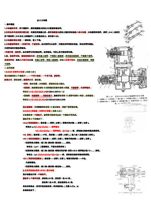
二.应用实例1.BJ2020吉普车分动器(见图3-26)该分动器设有2个操纵杆——一个用于换挡;一个用于接、摘前桥。
换档方式:滑动齿轮;接前桥方式:接合套。
▲空档:图示位置;分动器前、后轴均无动力输出。
▲高速档:换挡滑动齿轮10前移通过花键与齿轮9联接,不接前桥;只后桥驱动;传动比i H=(Z11/Z2)×(Z9/Z11)=(31/20)×( 24/31)= 1.2▲低速档:先接前桥——用接合套6,换挡滑动齿轮10后移与齿轮4啮合;全轮驱动;传动比i D=(Z11/Z2)×(Z10/Z4)=(31/20)×(41/24)=2.648退出低速档:先将换挡滑动齿轮10退出啮合;再摘下前桥接合套。
2.BJ2021(切诺基)吉普车分动器(见图3-29)分动器设有一个操纵杆。
接前桥与换挡均由这一个操纵杆来完成。
操纵杆有4个位置如下:▲4L(4轮低速驱动):接合套——前移(左移);锁销式同步器——后移(右移)。
传动比i4L=(Z11/Z2)×(Z4/Z8)——后桥输出=(Z11/Z2)×(Z9/Z8)——前桥输出。
东风EQ1092F型汽车分动器的设计
摘要东风EQ1092F型汽车作为我国较先进的军用和民用汽车,有着广泛的用途和重要的作用。
在多轴驱动的汽车上,为了将输出的动力合理的分配给各驱动桥,设有分动器。
分动器的功用就是将变速器输出的动力分配到个驱动桥,并且进一步增大扭矩。
分动器也是一个齿轮传动系统,它单独固定在车架上,其输出轴与分动器的输出轴用万向传动装置连接,分动器的输出轴有若干根,分别经万向传动装置与各驱动桥相连。
越野汽车在良好的道路行驶时,为减少功率消耗及传动系机件和轮胎磨损,一般要切断通向前桥的动力。
在越野行驶时,根据需要接合前桥并采用低速档,增加驱动轮数和驱动力。
本文概述了分动器的现状和发展趋势,介绍了分动器领域的最新发展状况,对工作原理做了阐述。
本设计选用机械式分动器,其具有结构简单、传动效率高、制造成本低和工作可靠等优点。
主要说明了三轴式分动器的设计和计算过程,选择合理的结构方案进行设计,对分动器高低档齿轮和轴以及轴承做了详细的设计计算,并进行了受力分析、强度和刚度校核计算,对一些标准件进行了选型以及壳体得设计。
关键词:分动器;三轴式;高低档;校核;齿轮传动。
ABSTRACTThe DongfengEQ1092 cars are more advanced military and civilian cars, which are used widely and take the important role. In order to output the power to drive axle reasonably we settle transfer case drive in the car. The function of transfer case is output the power which from the gear box to drive axle and increase the torque. T he transfer case is a gear transmission system .It is fixed on the frame alone. The output axis and the transfer case output axis are connected by universal driven device .There are several output axis in transfer case, which link to driving axle by universal driving device .When the cross country vehicle running on the good way ,it always cut down the power to front axle in order to reduce consumption of transmitting mechanism and wheel. According to the need ,the cars connect the front axis and use low speed when in the off-road driving to increase the number of driven wheels and drive power. This paper outlines the transfer case and its further development meanwhile describe the theory of work. This design takes mechanical transfer case. It has a simple structure, high transmission efficiency, low manufacturing cost and working and reliable. Mainly to explain the three-axis sub-actuator design and calculation process, a reasonable choice to design the structure of the program. Accounting the low and high gear of transfer case and drive axis detailedly and analyses the stress and strength . Carrying out the type selected and shell design in a number of standard parts.Keywords:Thansfer; Triaxial type; Check; High low-grade; Gear transmission目录摘要 (I)ABSTRACT (II)第1章绪论 (1)1.1 概述 (1)1.2 分动器类型和发展 (1)1.3 分动器的功用及意义 (2)1.4 设计内容 (3)第2章分动器结构的确定及主要参数的计算 (4)2.1 设计所依据的主要技术参数 (4)2.2分动器的设计要求 (4)2.3 分动器结构方案的选择 (4)2.4 传动方案 (5)2.5 齿轮的安排 (5)2.6 换挡结构形式 (6)2.7分动器壳体 (6)2.8分动器的操纵机构设计 (7)2.9 传动比的计算 (7)2.10 中心距A确定 (8)2.11 本章小结 (9)第3章分动器的齿轮设计 (10)3.1 模数的确定 (10)3.2 齿形压力角及螺旋角 (10)3.3 齿宽 (11)3.4 各档齿轮齿数的确定 (11)3.4.1 低速档齿轮副齿数的确定 (11)3.4.2 对中心距进行修正 (12)3.4.3 确定其他齿轮的齿数 (13)3.5 齿轮损坏的原因和形式 (14)3.6 齿轮的材料选择 (15)3.7 齿轮的强度计算 (16)3.7.1 轮齿的弯曲应力 (16)3.7.2 轮齿触应接力 (19)3.8 本章小结 (22)第4章轴的设计 (23)4.1轴的尺寸初选 (23)4.2 轴的结构设计 (23)4.3 花键的形式和尺寸 (26)4.4 轴承的设计 (26)4.5齿轮和轴上的受力计算 (28)4.6 轴的强度校核 (30)4.7 本章小结 (33)结论 (34)参考文献 (35)致谢 (36)附录 (37)第1章绪论1.1 概述东风EQ1092F型汽车作为我国较先进的军用和民用汽车,有着广泛的用途和重要的作用[17]。
Parker Hannifin 水力泵和动力分割器分类 F12 系列服务手册说明书
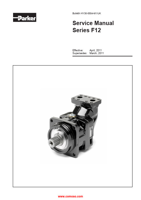
Effective: April, 2011Supersedes:March, 2011Bulletin HY30-5504-M1/UKService Manual Series F122Parker HannifinPump and Motor Division Trollhättan, SwedenService Manual Series F12HY30-5504-M1/UKList of contents PageGeneral information ...................................................................................3Specifications ............................................................................................4Disassembling ....................................................................................5 - 10Assembling F12-30/40/60/80/90/110/125 .........................................11 - 16Change of shaft seal ...............................................................................17Valve plates .............................................................................................18Splitview F12-150.................................................................................... 19Assembling F12-150......................................................................... 20 - 22Splitview F12-250.................................................................................... 23Assembling F12-250......................................................................... 24 - 28Test procedure.. (29)Conversion factors1 kg = 2.2046 lb 1 N = 0.22481 lbf 1 bar = 14.504 psi 1 l = 0.21997 UK gallon 1 l = 0.26417 US gallon1 cm 3= 0.061024 in 31 m = 3.2808 feet 1 mm = 0.03937 in 9/5 °C + 32 = °FOffer of SalePlease contact your Parker representation for a detailed ”Offer of Sale”.FAILURE OR IMPROPER SELECTION OR IMPROPER USE OF THE PRODUCTS AND/OR SYSTEMS DESCRIBED HEREIN OR RELATED ITEMS CAN CAUSE DEATH, PERSONAL INJURY AND PROPERTY DAMAGE.This document and other information from Parker Hannifin Corporation, its subsidiaries and authorized distributors provide product and/or system options for further investigation by users having technical expertise. It is important that you analyze all aspects of your application, including consequences of any failure, and review the information concerning the product or sys-tem in the current product catalogue. Due to the variety of operating conditions and applications for these products or systems, the user, through its own analysis and testing, is solely responsible for making the final selection of the products and systems and assuring that all performance, safety and warning requirements of the application are met.The products described herein, including without limitation, product features, specifications, designs, availability and pricing, are subject to change by Parker Hannifin Corporation and its subsidiaries at any time without notice.WARNING!3Parker HannifinPump and Motor Division Trollhättan, SwedenService Manual Series F12HY30-5504-M1/UKGeneral informationF12 is bent axis, fixed displacement heavy-duty motor/pump seris. They can be used in numerous applications in both open and closed loop circuits.Series F12 conforms to current ISO and SAE mounting flange and shaft end configu -rations. A very compact cartridge version is also available.Frame sizes: F12-30, -40, -60, -80, -90, -110, -125, -150, -250.Thanks to the unique spherical piston de-sign, F12 motors can be used at unusually high shaft speeds. Operating pressures to 480 bar provides for the high output power capability.The 40° angle between shaft and cylinder barrel allows for a very compact, lightweight motor/pump.The laminated piston ring offers important advantages such as low internal leakage and thermal shock resistance.The pump version has highly engineered valve plates for increased selfpriming speed and low noise, available with left and right hand rotation.The F12 motors produce very high torque at start-up as well as at low speeds.Our unique timing gear design synchronizes shaft and cylinder barrel, making the F12 very tolerant to high ’G’ forces and torsional vibrations.Heavy duty roller bearings permit substan-tial external axial and radial shaft loads.The F12’s have a simple and straightfor-ward design with very few moving parts, making them very reliable motors/pumps.The unique piston locking, timing gear and bearing set-up as well as the limited num-ber of parts add up to a very robust design with long service life and, above all, proven reliability.F12 cross section1. Barrel housing2. Valve plate3. Cylinder barrel4. Piston with piston ring5. Timing gear6. Tapered roller bearing7. Bearing housing8. Shaft seal9. Output/input shaft4Parker HannifinPump and Motor Division Trollhättan, SwedenService Manual Series F12HY30-5504-M1/UKOperating temeratureThe following temperatures should not be exceeded (N shaft seals): Drain fluid: 90 o C.FPM shaft seals (type V ) can be used to 115 o C drain fluid temperature.NOTE: The temperature should be measured at the utilized drain port.Continuous operation may require case flushing inorder to meet the viscosity and temperature limitations.For further information we refer to:Catalogue HY30-8249/UKFrame sizeF12-030F12-040F12-060F12-080F12-090F12-110F12-125F12-150F12-250Displacement (cm 3/rev)30.040.059.880.493.0110.1125.0150.0242.0Operating Pressure max intermittent 1) (bar)480480480480420480480420420max continuous (bar)420420420420350420420350350Motor operating speed max intermittent 1) (rpm)7 300 6 700 5 800 5 300 5 000 4 800 4 60035003000max continuous (rpm) 6 700 6 100 5 300 4 800 4 600 4 400 4 20032002700min continuous (rpm)505050505050505050Max pump sefprimingspeed 2)L or R function; max (rpm)31502870 2 500 2 300 2 250 2 200 2 10017001500Motor input flow max intermittent 1) (l/min)219256347426465528575525726max continuous (l/min)201244317386428484525480653Main circuit temp.3)max (o C)808080808080808080min (o C)-40-40-40-40-40-40-40-40-40Mass moment of inertia(x10-3) (kg m 2)1.72.9 5.08.48.411.211.240.046.0Weight(kg)12.016.521.026.026.036.036.070.077.01) Intemittent: max 6 seconds in any one minute.2) Selfpriming speed valid at sea level.3) See also below, operating temperature.5Parker HannifinPump and Motor Division Trollhättan, SwedenService Manual Series F12HY30-5504-M1/UKDisassembleFasten the unit in a vice. Loosen the 4 boults (item 491).491Disassemble the barrel housing (item 110). Make sure that the valve plate doesn’t fall out when lifting the barrel housing off.Remove the cylinder barrel (item 411). Take the shim (item 488) away.1104114886Parker HannifinPump and Motor Division Trollhättan, SwedenService Manual Series F12HY30-5504-M1/UKRemove the barrel support (item 430).Disassemble the pistons (item 440).Remove the O-ring (item 221).4304402217Parker HannifinPump and Motor Division Trollhättan, SwedenService Manual Series F12HY30-5504-M1/UK237Disassemble the retaining ring (item 237).231Remove the seal carrier (item 231).225Remove the O-ring (item 225).8Parker HannifinPump and Motor Division Trollhättan, SwedenService Manual Series F12HY30-5504-M1/UK478Disassemble the retaining ring (item 478).476Remove the spacer washer (item 476).311211Place the bearing housing (item 211) on a tube. Press uot the shaft (item 311) by pres-sing on the shaft end.9Parker HannifinPump and Motor Division Trollhättan, SwedenService Manual Series F12HY30-5504-M1/UKRemove the small tappered roller bearing (item 470).Tap the small bearing ring off with a mandrel.Tap the large bearing ring off with a mandrel.47010Parker HannifinPump and Motor Division Trollhättan, SwedenService Manual Series F12HY30-5504-M1/UKPlace the ring gear (item 452) on a tube. Press the shaft (item 311) out with a press.452311TubePress down the bearing ring (item 460) in the bearing housing (item 211) with a press. Use a tube to match the outer diameter off the bearing ring.211Press down the bearing ring (item 470) in the bearing housing (item 211) with a press. Use a tube to match the outer diameter off the bearing ring.211Press down the tappered roller bearing (item 460) and the ring gear (item 452) on the shaft with a press. Use a tube (see page 16).460452Assemble F12-30/40/60/80/90/110 and 125Press down the Bearing (item 470) witha press until correct preload is achieved.Install the spacer washer (item 476). 476Install the retaining ring (item 478).478Install the O-ring (item 225).225Install the seal carrier (item 231). 231Install the retaining ring (item 237). 237Install the O-ring (item 221).221440Install the pistons (item 440).430Install the barrel support (item 430).488Install the shim (item 488).411Install the cylinder barrel (item 411). Ensure correct timing. (marking - punch mark)Put some grease on the valve plate (item 121) and install it into the barrel housing (item 110).Make sure you have installed the valve plate correct (see page 18).121110Install the barrel housing (item 110).Fasten two bolts and secure that the back-lash is between 0,1 - 0,3 mm. Check it with a feeler gauge in the drain port.At the same time double check the timing,(marking - punch mark).110...Fasten the 4 boults (item 491) to specified torque.F12-030 65 ± 10 Nm F12-040 65 ± 10 Nm F12-060 65 ± 10 Nm F12-080 115 ± 10 Nm F12-090 115 ± 10 Nm F12-110 115 ± 10 Nm F12-125 115 ± 10 Nm F12-150 220 ± 35 Nm F12-250 220 ± 35 Nm491Type ØA ØB ØC F12-030 60 49 42F12-040 65 58 52F12-060 73 64 57F12-080/090 74 70 62F12-110/125 82 75 67F12-150/250 97 - 82Tools to be used to facilitate theinstallation of the tappered roller bearings.Remove the retaining ring (item 237).Remove the seal carrier (item 231).Tap the shaft seal out with hammer andmandrel.Tap the new shaft seal back with a tube anda hammer.The outside diameter on the tube is 65mm. 237231Change of shaft sealValve plates F12Following valve plates can be fitted in F12.RGXR = R.H. rotation, pump operationG = L.H. rotation, internal drain, motor operationX = Bi-directional, pump operation, high self priming speedAgainst cylinder barrelAgainst cylinder barrelMLM = Bi-directional, motor operationL = L.H. rotation, pump operationAgainst cylinder barrel491464460452321440411431121310486488222221130110415237236233211475474470Splitview F12-150Assembly F12-1501. Press down the tappered roller bea-ring (item 460) and the ring gear (item 452) on the shaft with a press. Use atube (see page 16). 2. Carefully press down the tappered roller bearing (item 470) until correct preload of the bearing package isachieved. Use a tube (see page 16).3. Assemble the lock washers (item 474) and the round nut (item 475). Tap in the lock washers to lock the roundnut.4. Assemble the pistons (item 440). Lubricate the ball sockets before assembling.Assembly F12-1505. Assemble the valve plate (item 121) in the barrel housing (item 110). Make sure you have installed the valve plate correct (see page 18).6. Tap down the cylinder barrel (item 411) with barrel retaining ring (item 431) and needle bearings (item 415) Use a plastic collar.7. Assemble the shims (item 488) and the guide spacer (item 486). Lo-cate one opening in the guide spacer against the drain connection on the barrel housing.8. Assemble the bearing package withpistons.Assembly F12-1509. Make sure the timing is correct.10. Assemble the shaft seal (item 233) and the support ring (item 236). Locate the chamfer on the support ring down-wards.Tap it down with a plastic collar.11. Assemble the retaining ring (item 237). Lubricate the shaft seal before assembling the housing.12. Assemble the bearing housing (item 211), tap it down with a plastic hammer.Torque the screws to 220 ± 35 Nm.488*3429428493*3222321413*3424411440*9414423224415*2422425433427426475474470464460452237211233236130481491*4111223310Splitview F12-250Assembly F12-2501. Press down the tappered roller bea-ring (item 460) and the ring gear (item 452) on the shaft with a press. Use a tube (see page 16).2. Carefully press down the tappered roller bearing (item 470) until correct preload of the bearing package is achieved. Use a tube (see page 16).3. Assemble the lock washers (item 474) and the round nut (item 475). Tap in the lock washers to lock the round nut.4. Assemble the shaft seal (item 233) and the support ring (item 236). Locate the chamfer on the support ring down-wards.Tap it down with a plastic collar. Assemble the retaining ring (item 237). Lubricate the shaft seal before assem-bling the housing.Assembly F12-2505. Tap down the bearing package into the bearing housing (item 211) by usinga plastic collar and a plastic hammer.6. Assemble the pistons (item 440). Lubricate the ball sockets before assembling.7. Assemble the tap rol bearing (item 425), the disc spring (item 433), the spacer washer (item 426) and the re-taining ring (item 427).8. Press down the bearing ring (item 425), the spacer sleeve (item 422), the neddle bearings (item 415) and the retaining ring (item 414).Locate the needle bearings against the retaining ring.Assemble the spring pins (item 413)and the sliding plate (item 424).Assembly F12-2509. Assemble the cylinder barrel (item 411) on the pistons (item 440). Make sure the timing is correct.10. Assemble the O-ring (item 222) on the barrel housing (item 481). Lubricate the O-ring.11. Assemble the barrel housing. Make sure the cylinder barrel is in correct position by holding the barrel spindle (item 423). Tap the housing down witha plastic hammer.12. Assemble the O-rings (item 223 and 224) on the end cap (item 111).Lubricate the O-rings.Assembly F12-25013. Place the end cap on to the barrel housing until the O-ring is entered. 14. Fit a long screw (M12) to the barrel spindle and pull the barrel spindle up with a universal pliers.15. Knock down the end cap with a plastic hammer and fit shims (item 488) and hexagon screws (item 493). Torque the screws to 330 ± 10 Nm. 16. Install the cap screw (item 428) thatsecures the barrel spindle.Assembly F12-25017. Torque the cap screw to 40 - 45 Nm and back off 1/3 off a turn to obtain correct axial play.18. Hit the cap screw one time to obtain back-lash. Make sure the back-lash is correct.The general condition of the unit can be established by checking the drain flow. Remove the drain line and keep the drain port above a suitable container. Run the unit at normal speed and pressurize the system to 2000-3000 psi. (150 - 200 bar)Measure the drain flow for one minute; if it exceeds the maximum figures shown below, the unit is worn or damaged internally and should be replaced or repaired. Also, check for leakage at the shaft seal and between the bearing and barrel housings.Series Normalcu.in./min Normall/minMaxgpm.Maxl/minF12-030240.4.55 2.0 F12-040300.5.65 2.5 F12-060430.7.70 2.7 F12-08061 1.0.80 3.0 F12-09061 1.0.80 3.0 F12-11061 1.0.80 3.0 F12-12561 1.0.80 3.0 F12-15073 1.2.80 3.0 F12-25092 1.5.80 3.0Notes:31Parker Hannifin Pump and Motor Division Trollhättan, SwedenService Manual Series F12HY30-5504-M1/UK Notes:Parker HannifinPump and Motor Division Flygmotorvägen 2SE-461 82 Trollhättan SwedenTel: +46 (0)520 40 45 00 Fax: +46 (0)520 371 05 。
分动器 介绍

21 Optional: CONFIDENTIAL INFORMATION
(Optional: Identify event)
主动技术与被动技术比较
“主动” 系统: 主动” 系统:
• 根据整车的运动状态,提供自动的,连续可变的反应模式. 根据整车的运动状态,提供自动的,连续可变的反应模式.
“被动” 系统: 被动” 系统:
(Optional: Identify event)
8 Optional: CONFIDENTIAL INFORMATION
(Optional: Identify event)
9 Optional: CONFIDENTIAL INFORMATION
(Optional: Identify event)
26 Optional: CONFIDENTIAL INFORMATION
(Optional: Identify event)
TOD的优点
增强整车的兼容性
– 无须增加额外的离合器等零部件,可以与ABS,ESP,TCS系统兼 容 – 利用CAN 系统实现在线通讯
增强增车的驾驶舒适性和灵活性
– 转弯或停车时无转向制动现象 – 加速是可实现最佳的牵引动力
(Optional: Identify event)
Agenda
电动分动器 TOD(适时分动器)
13 Optional: CONFIDENTIAL INFORMATION
(Optional: Identify event)
TOD (适时分动器)
TOD分单速TOD及双速TOD两种产品,双速TOD相对单速 TOD增加了一个4L档位。 单速TOD有2H和自动(ATUO)档位,通过换档开关实现 档位切换。如果整车不设2H档位,只有AUTO档的情况下 ,不需换档开关,TOD根据路况,智能控制四驱状态, 适时传递大小可控扭矩给前桥。 双速TOD有2H、ATUO及4L档位,在ATUO档时,同样根据 路况,传递大小可控扭矩。增加的4L档位,用于低速越 野路面。 TOD属主动技术产品,而电动分动器属被动技术产品。
ZQC1600分动器产品技术规格说明书
产品简介
ZQC1600型分动器是自主研发的与重型越野汽车 配套的新产品,具有国际同类产品先进水平,产 品结构为三轴两档式,内置润滑油泵,润滑好, 使用寿命长。总成承载能力强,该总成适配于 550马力以下发动机,最大整车总质量80吨。可 匹配军车、沙漠车及其它全轮驱动商用汽车。
润滑油量(加注至油标) 总质量 可选装置
带差速器 8.4L 350Kg 可选装N200取力器或ZF8605油泵连接装置
不带差速器 9.0L 335Kg
版权所有:潍柴动力股份有限公司 沪ICP 备10010924号
产品图片
Hale Waihona Puke 命名规则技术参数表最大输入扭矩 最大输入转速 / 输入转向 输入输出中心距 速比
18000Nm 2800rpm / 顺时针 300或396mm 系列 1 高档 0.89 位置 朝后 低档 1.536
换档操作 前桥输出操作(或差速锁操作) 轴间差速器前后分扭比 气动操作气压
类型 三位气动 气动操作带指示开关 1 : 2.214\1:2.69\1:3.0(可选不带差速器) 6.5~8 bar
- 1、下载文档前请自行甄别文档内容的完整性,平台不提供额外的编辑、内容补充、找答案等附加服务。
- 2、"仅部分预览"的文档,不可在线预览部分如存在完整性等问题,可反馈申请退款(可完整预览的文档不适用该条件!)。
- 3、如文档侵犯您的权益,请联系客服反馈,我们会尽快为您处理(人工客服工作时间:9:00-18:30)。
毕业设计(论文)中文摘要毕业设计(论文)外文摘要目录1绪论 (1)1.1 毕业设计任务及要求 (1)1.2 分动器的公用和设计要求 (1)2 分动器结构方案的选择 (2)2.1 传动方案 (2)2.2 齿轮的安排 (2)2.3 换档结构形式 (3)3 分动器主要参数的选择 (4)3.1传动比分配 (4)3.2 中心距A (4)4 分动器齿轮参数的确定 (4)4.1 模数 (4)4.2 压力角 (4)4.3螺旋角 (5)4.4 齿宽 (5)4.5各档齿轮齿数的分配 (5)5 啮合套的设计计算 (7)6 分动器结构元件 (7)6.1 齿轮 (7)6.2 轴及相关零件 (8)6.3 分动器壳体 (11)7 零件的校核 (12)7.1 齿轮的校核 (12)7.2 轴的校核 (13)8 分动器操纵机构 (16)9 工艺分析 (17)9.1 壳体加工工艺 (17)9.2 拨叉加工工艺 (17)9.3 齿轮加工工艺 (18)9.4 轴的加工工艺 (19)9.5 总成的装配 (19)结论 (21)致谢 (22)参考文献 (23)1 绪论越野车需要经常在坏路和无路情况下行驶,尤其是军用汽车的行驶条件更为恶劣,这就要求增加汽车驱动轮的数目,因此,越野车都采用多轴驱动。
例如,如果一辆前轮驱动的汽车两前轮都陷入沟中(这种情况在坏路上经常会遇到),那汽车就无法将发动机的动力通过车轮与地面的磨擦产生驱动力而继续前进。
而假如这辆车的四个轮子都能产生驱动力的话,那么,还有两个没陷入沟中的车轮能正常工作,使汽车继续行驶。
在多轴驱动的汽车上,为了将输出的动力分配给各驱动桥设有分动器。
1.1 毕业设计任务及要求题目:EQ2080型汽车分动器设计设计参数:课题内容:完成分动器的选型、设计计算并绘制相关图纸。
装配图1张(0号图);齿轮零件图4张(2号图);输入、输出轴,中间轴3张(2号图);动力传动示意图1张(2号图)。
其中要有计算机绘制的图样。
1.2 分动器的功用和设计要求分动器的功用就是将分动器输出的动力分配到各驱动桥,并且进一步增大扭矩。
分动器也是一个齿轮传动系统,它单独固定在车架上,其输入轴与分动器的输出轴用万向传动装置连接,分动器的输出轴有若干根,分别经万向传动装置与各驱动桥相连。
汽车全轮驱动,可在冰雪、泥沙和无路的地区地面行驶。
对分动器的设计要求要满足以下几点:1)便于制造、使用、维修以及质量轻、尺寸紧凑;2)保证汽车必要的动力性和经济性;3)换档迅速、省力、方便;4)工作可靠。
不得有跳档及换档冲击等现象发生;5)分动器应有高的工作效率;6)分动器的工作噪声低。
2 分动器结构方案的选择分动器的结构形式是多种多样的,各种结构形式都有其各自的优缺点,这些优缺点随着主观和客观条件的变化而变化。
因此在设计过程中我们应深入实际,收集资料,调查研究,对结构进行分析比较,并尽可能地考虑到产品的系列化、通用化和标准化,最后确定较合适的方案。
机械式具有结构简单、传动效率高、制造成本低和工作可靠等优点,在不同形式的汽车上得到广泛应用。
本设计采用的结构方案如图2-1所示。
图 2-1 分动器传动示意图2.1 传动方案分动器的设计类比于变速器和减速器的设计。
现在汽车大多数都采用中间轴式变速器,由《汽车构造》中EQ208型汽车分动器的结构图,采用输入轴与后轮输出轴同轴的形式,输入轴的后端经轴承在后轮输出轴的轴孔内,后轮输出要经过两对齿轮副的传递,因此传动效率有所降低。
2.2 齿轮的安排各齿轮副的相对安装位置,对于整个分动器的结构布置有很大的影响,要考虑到以下几个方面的要求:1)整车总布置根据整车的总布置,对分动器输入轴与输出轴的相对位置和分动器的轮廓形状以及换挡机构提出要求2)驾驶员的使用习惯3)提高平均传动效率4)改善齿轮受载状况各挡位齿轮在分动器中的位置安排,考虑到齿轮的受载状况。
承受载荷大的低挡齿轮,安置在离轴承较近的方,以减小铀的变形,使齿轮的重叠系数不致下降过多。
分动器齿轮主要是因接触应力过高而造成表面点蚀损坏,因此将高挡齿轮安排在离两支承较远处。
该处因轴的变形而引起齿轮的偏转角较小,故齿轮的偏载也小。
2.3 换档结构形式目前用于齿轮传动中的换挡结构形式主要有三种:1)滑动齿轮换挡通常是采用滑动直齿轮进行换挡,但也有采用滑动斜齿轮换挡的。
滑动直齿轮换挡的优点是结构简单、紧凑、容易制造。
缺点是换挡时齿端面承受很大的冲击,会导致齿轮过早损坏,并且直齿轮工作噪声大。
所以这种换挡方式,一般仅用在较低的档位上,例如变速器中的一挡和倒挡。
采用滑动斜齿轮换挡,虽有工作平稳、承裁能力大、噪声小的优点,但它的换挡仍然避免不了齿端面承受冲击。
2)啮合套换挡用啮合套换挡,可将构成某传动比的一对齿轮,制成常啮合的斜齿轮。
而斜齿轮上另外有一部分做成直的接合齿,用来与啮合套相啮合。
这种结构既具有斜齿轮传动的优点,同时克服了滑动齿轮换挡时,冲击力集中在1~2个轮齿上的缺陷。
因为在换挡时,由啮合套以及相啮合的接合齿上所有的轮齿共同承担所受到的冲击,所以啮合套和接合齿的轮齿所受的冲击损伤和磨损较小。
它的缺点是增大了分动器的轴向尺寸,未能彻底消陈齿轮端面所受到的冲击。
本设计中倒挡采用这种换挡方式。
3)同步器换挡现在大多数汽车的变速器都采用同步器。
使用同步器可减轻接合齿在换挡时引起的冲击及零件的损坏。
并且具有操纵轻便,经济性和缩短换挡时间等优点,从而改善了汽车的加速性、经济性和山区行驶的安全性。
其缺点是零件增多,结构复杂,轴向尺寸增加,制造要求高,同步环磨损大,寿命低。
但是近年来,由于同步器广泛使用,寿命问题已解决。
比如在其工作表面上镀一层金属,不仅提高了耐腐性,而且提高了工作表面的摩擦系数。
3 分动器主要参数的选择 3.1传动比分配高速级传动比:08.1i =高;低速级传动比:05.2i =低。
3.2 中心距A将中间轴与第二轴之间的距离称为中心距A 。
它是一个基本参数,其大小不仅对分动器的外形尺寸、体积个质量大小,而且对轮齿的接触强度有影响。
中心距越小,齿轮的接触应力越大,齿轮寿命越短。
因此,最小允许中心距应当由保证轮齿有必要的接触强度来确定。
分动器的轴经轴承安装在壳体上,从布置轴承的可能与方便和不影响壳体的强度考虑,要求中心距取大些。
4 分动器齿轮参数的确定 4.1 模数齿轮模数是一个重要参数,并且影响它的选取因素又很多,如齿轮的强度、质量、噪声、工艺要求、载荷等。
决定齿轮模数的因素很多,其中最主要的是载荷的大小。
由于高档齿轮和低档齿轮载荷不同,股高速挡和低速档的模数不宜相同。
从加工工艺及维修观点考虑,同一齿轮机械中的齿轮模数不宜过多。
根据国家标准GB1357—78的规定,选取各齿轮副模数如下:常啮合齿轮:m n =4mm ; 低速档:m n =4mm , 高速挡:m n =3mm 。
啮合套采用渐开线齿形,取m=3mm 。
4.2 压力角α压力角较小时,重合度较大,传动平稳,噪声较低;压力角较大时,可提高轮齿的抗弯强度和表面接触强度。
对于轿车,为加大重合度以降低噪声,应取用小些的压力角;对于货车,为提高齿轮承载能力,应取用大些的压力角。
实际上,因国家规定的标准压力角为ο20,所以分动器齿轮采用的压力角为ο20。
4.3 螺旋角β螺旋角β一般范围为10°~35°。
螺旋角增大使齿轮啮合系数增加、工作平稳、噪声降低、另外齿轮的强度也有所提高。
但螺旋角太大,会使轴向力及轴承载荷过大。
初选低速档啮合齿轮螺旋角β=20°。
关于螺旋角的方向,输入轴齿轮采用右旋,这样可使第一轴所受的轴向力直接经过轴承盖作用在分动器壳体上,避免了因轴向力一二两轴抱死的现象。
中间轴齿轮全部采用左旋,因此中间轴上同时啮合的两对齿轮轴向力方向相反,轴向力可互相抵消一部分。
4.4 齿宽齿轮宽度大,承载能力高。
但齿轮受载后,由于齿向误差及轴的挠度变形等原因,沿齿宽方向受力不均匀,因而齿宽不宜太大。
齿宽可根据下列公式初选:直齿轮b=(4.5~7.5)m,斜齿轮b=(6.0~8.5)m n 。
综合各个齿轮的情况,均为斜齿轮,齿宽选为30mm 。
4.5 各档齿轮齿数的分配 4.5.1 确定低速档齿轮副齿数在初选中心距、齿轮模数和螺旋角以后,可根据档数、传动比和传动方案来分配各档齿轮的齿数。
齿数和:1.61420cos 1302cos 2z S 21=⨯⨯==+=οn m A z β圆整取S=61根据经验数值,一轴低速档齿轮齿数在z 1=24~28之间选取。
不妨通过下列关系对着三个数值得出的参数进行比较。
表 4-1 不同齿数时传动比对比z 1 z 2 Z 3 Z 4 I 低 24 37 35 26 2.075 25 36 36 25 2.074 26 35 37 24 2.075 27 34 38 23 2.081 283339222.089通过比较可以得出z 1=25,z 2=36时,i 低=2.074,与设计要求2.05最接近。
下面以z 1=25为例对计算过程进行说明: z 1=25,z 2=36mm mm A n 8.12920cos 2461cos 2Sm =⨯⨯==β修正中心距,取A=130。
重新确定螺旋角β,其精确值应为9121202052.201302614cos 2cos12'''==⨯⨯==οοA S m n β 下面根据方程组:4236.1362505.261420cos 1302cos 221431243=⨯===⨯⨯==+z z i z z m A z z n 低οβ确定常啮合齿轮副齿数分别为2536z 43==z ,。
重新确定螺旋角β,其精确值为表4-2 各齿轮基本参数齿轮高速档低速档常啮合齿轮齿数 输入轴齿轮6中间轴 齿轮7 输入轴 齿轮1 中间轴 齿轮2 输出轴 齿轮3 中齿4735253636实际传动比i 0.7451.441.44 螺旋角β 613518'''ο912120'''ο912120'''ο法面模数m n (mm ) 3 4 4 法面齿顶高系数*an h1 1 1 法面顶隙系数*n c0.25 0.25 0.25 端面模数m t (mm ) 3.1707 4.2623 4.2623 分度圆压力角αn 20°20°20°分度圆直径d (mm ) 149.02110.98106.56153.44 153.4410中心距A (mm ) 130 130 130 中心距变动系数 0 0 0 齿顶高h a (mm ) 3 4 4 齿根高h f (mm ) 3.75 5 5 齿全高h (mm ) 6.75 9 9 有效齿宽b (mm ) 303030当量齿数z v 55.4941.32 30.2543.5643.5635 啮合套传动副的设计计算啮合套轮齿为直齿,其齿廓曲线为渐开线,啮合角为20°,模数取3mm ,齿顶高系数5.0h a =*,其他参数与普通齿轮一样,齿数一般为30~80。