DC3003A使用说明书
California Instruments Asterion线电源系列说明书
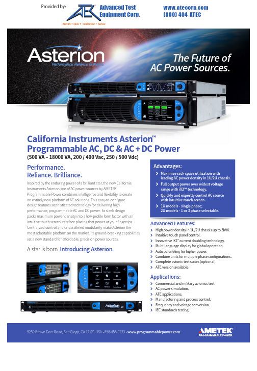
9250 Brown Deer Road, San Diego, CA 92121 USA • 858-458-0223 • Performance.Reliance. Brilliance.Inspired by the enduring power of a brilliant star, the new California Instruments Asterion line of AC power sources by AMETEKProgrammable Power combines intelligence and flexibility to create an entirely new platform of AC solutions. This easy-to-configure design features sophisticated technology for delivering high performance, programmable AC and DC power. Its sleek designpacks maximum power density into a low-profile form factor with an intuitive touch screen interface placing that power at your fingertips. Centralized control and unparalleled modularity make Asterion themost adaptable platform on the market. Its ground-breaking capabilities set a new standard for affordable, precision power sources.A star is born. Introducing Asterion.Advanced Features:k High power density in 1U/2U chassis up to 3kVA.k Intuitive touch panel control.k Innovative iX2™ current doubling technology.k Multi-language display for global operation.k Auto paralleling for higher power.k Combine units for multiple phase configurations.k Complete avionic test suites (optional).kATE version available.Applications:k Commercial and military avionics test.k AC power simulation.k ATE applications.kManufacturing and process control. k Frequency and voltage conversion.kIEC standards testing.Advantages:k Maximize rack space utilization withleading AC power density in 1U/2U chassis.k Full output power over widest voltagerange with iX2™ technology.k Quickly and expertly control AC sourcewith intuitive touch screen.k 1U models - single phase;2U models - 1 or 3 phase selectable.California Instruments Asterion ™Programmable AC, DC & AC + DC Power(500 VA – 18000 VA, 200 / 400 Vac, 250 / 500 Vdc)Provided by: (800)404-ATECAdvanced Test Equipment Corp .®Rentals • Sales • Calibration • ServiceAsterion AC Series: Product Specifications & Details9250 Brown Deer Road, San Diego, CA 92121 USA • 858-458-0223 • Avionics TestPower SimulationATE ApplicationsManufacturingFrequency ConversionIEC Standards TestingVirtual Panels allow remote control of the Asterion AC power sourceas well as programming communication and monitoring for the Asterion ATE model without front panel display.Virtual PanelsSee Data Sheet for Ratings > 1kHz to 5kHzFull Power AvailableAC/DC Output Specifications。
Edge Gateway 3003 安装和操作手册说明书

Edge Gateway 3003安装和操作手册计算机型号: Edge Gateway 3003管制型号: N03G管制类型: N03G001注、小心和警告注: “注”表示帮助您更好地使用该产品的重要信息。
小心: “小心”表示可能会损坏硬件或导致数据丢失,并说明如何避免此类问题。
警告: “警告”表示可能会造成财产损失、人身伤害甚至死亡。
目录1 概览 (5)2 系统视图 (6)顶部视图 (6)底部视图 (6)左侧视图 (7)右侧视图 (9)3 安装 Edge Gateway (10)安全与管制信息 (10)专业安装说明 (10)Instructions d'installation professionnelles (11)联邦通信委员会干扰声明 (11)加拿大工业部声明 (11)设置 Edge Gateway (12)激活移动宽带服务 (17)安装边缘网关 (19)使用标准安装架安装 Edge Gateway (19)使用快速安装架安装 Edge Gateway (26)将电缆控制条连接至标准安装架 (34)使用 DIN 导轨架将 Edge Gateway 安装在 DIN 导轨上。
(36)使用垂直安装架安装 Edge Gateway (39)使用 VESA 安装架安装 Edge Gateway (42)4 设置 ZigBee 加密解密器 (44)5 设置操作系统 (45)Windows 10 IoT Enterprise LTSB 2016 (45)启动并登录—直接系统配置 (45)启动和登录—静态 IP 系统配置 (45)恢复 Windows 10 IoT Enterprise LTSB 2016 (45)Windows 10 IOT Enterprise LTSB 2016 基本功能 (46)Ubuntu Core 16 (47)概览 (47)启动并登录—直接系统配置 (47)启动并登录—静态 IP 系统配置 (47)更新操作系统和应用程序 (48)其他 Ubuntu 命令 (48)网络通信接口 (49)安全性 (51)Watchdog Timer (WDT) (52)恢复 Ubuntu Core 16 (52)3刷新新的 OS 映像 (53)创建恢复 USB 闪存盘 (54)6 访问和更新 BIOS (55)访问 BIOS 设置 (55)在 POST 过程中输入 BIOS 设置 (55)更新 BIOS (55)使用 USB 调用脚本 (55)从 USB 闪存驱动器刷新 BIOS (56)在 Windows 系统上更新 BIOS (56)在 Ubuntu 系统上使用 UEFI 压缩包更新 (56)Dell Command | Configure (DCC) (57)Edge Device Manager (EDM) (57)默认 BIOS 设置 (57)常规(BIOS 级别 1) (57)系统配置(BIOS 级别 1) (59)安全性(BIOS 级别 1) (60)安全引导(BIOS 级别 1) (61)性能(BIOS 级别 1) (61)电源管理(BIOS 级别 1) (61)POST 行为(BIOS 级别 1) (62)虚拟化支持( BIOS 级别1) (62)维护(BIOS 级别 1) (63)系统日志(BIOS 级别 1) (63)7 参考资料 (64)8 附录 (65)天线规格 (65)从 DIN 导轨架卸下 (66)连接到 Edge Gateway (66)Windows 10 IoT Enterprise LTSB 2016 (66)Ubuntu Core 16 (67)4概览Edge Gateway 3000 系列是物联网 (IoT) 设备。
莱士曼新能源科技有限公司DC DC转换器产品说明书
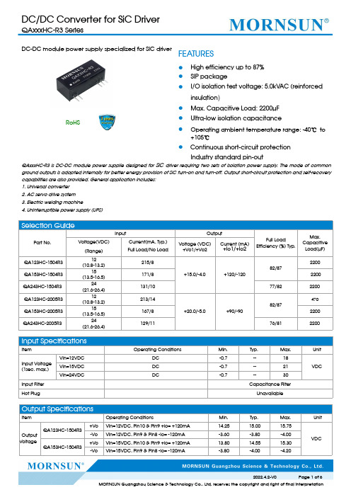
Selection GuidePart No.InputOutputFull LoadEfficiency (%)Typ.Max.Capacitive Load(µF)Voltage(VDC)(Range)Current(mA,Typ.)Full Load/No LoadVoltage (VDC)+Vo1/+Vo2Current (mA)+Io1/+Io2QA123HC-1504R312(10.8-13.2)215/8+15.0/-4.0+120/-12082/872200QA153HC-1504R315(13.5-16.5)171/82200QA243HC-1504R324(21.6-26.4)131/1077/822200QA123HC-2005R312(10.8-13.2)213/14+20.0/-5.0+90/-9082/87470QA153HC-2005R315(13.5-16.5)167/82200QA243HC-2005R324(21.6-26.4)129/1176/812200Input SpecificationsItemOperating ConditionsMin.Typ.Max.UnitInput Voltage (1sec.max.)Vin=12VDC DC -0.7--18VDC Vin=15VDC DC -0.7--21Vin=24VDCDC-0.7--30Input Filter Capacitance FilterHot PlugUnavailableOutput SpecificationsItem Operating ConditionsMin.Typ.Max.UnitOutput VoltageQA123HC-1504R3+Vo Vin=12VDC,Pin10&Pin9+Io=+120mA 14.2515.0015.75VDC -Vo Vin=12VDC,Pin9&Pin8-Io=-120mA -3.60-3.80-4.00QA153HC-1504R3+Vo Vin=15VDC,Pin10&Pin9+Io=+120mA 13.8014.5515.30-VoVin=15VDC,Pin9&Pin8-Io=-120mA-3.80-4.00-4.20DC-DC module power supply specialized for SIC driverRoHSFEATURES●High efficiency up to 87%●SIP package●I/O isolation test voltage:5.0kVAC(reinforced insulation )●Max.Capacitive Load:2200µF ●Ultra-low isolation capacitance●Operating ambient temperature range:-40℃to +105℃●Continuous short-circuit protection Industry standard pin-outQAxxxHC-R3is DC-DC module power supplie designed for SiC driver requiring two sets of isolation power supply.The mode of common ground outputs is adopted internally for better energy provision of SiC turn-on and turn-off.Output short-circuit protection and self-recovery capabilities are also provided.General application includes:1.Universal converter 2.AC servo drive system 3.Electric welding machine 4.Uninterruptible power supply (UPS)QA243HC-1504R3+Vo Vin=24VDC,Pin10&Pin9+Io=+120mA 14.5515.3016.05-Vo Vin=24VDC,Pin9&Pin8-Io=-120mA -3.96-4.16-4.36QA123HC-2005R3+Vo Vin=12VDC,Pin10&Pin9+Io=+90mA 18.6019.6020.60-Vo Vin=12VDC,Pin9&Pin8-Io=-90mA -4.95-5.20-5.45QA153HC-2005R3+Vo Vin=15VDC,Pin10&Pin9+Io=+90mA 18.4019.4020.40-Vo Vin=15VDC,Pin9&Pin8-Io=-90mA -4.85-5.10-5.35QA243HC-2005R3+Vo Vin=24VDC,Pin10&Pin9+Io=+90mA 19.0020.0021.00-VoVin=24VDC,Pin9&Pin8-Io=-90mA -4.75-5.00-5.25Voltage Accuracy 10%-100%load See output regulation curve (Fig.2)%Linear Regulation Full voltage input range+Vo Output --±1.1±1.5---Vo Output --±1.1±1.5Load Regulation 10%-100%load +Vo Output --815%-Vo Output--815Temperature Coefficient Full load--±0.04±0.1%/℃Ripple &Noise*20MHz bandwidth--50100mVp-pShort-circuit ProtectionContinuous,self-recoveryNote:*The “parallel cable”method is used for Ripple and Noise test,please refer to DC-DC Converter Application Notes for specific information.Mechanical SpecificationsCase Material Black plastic;flame-retardant and heat-resistant Dimensions 27.40x 9.50x 12.00mm Weight5.3g (Typ.)Cooling MethodFree air convectionElectromagnetic Compatibility (EMC)Emissions CE CISPR32/EN55032CLASS A (see Fig.7for recommended circuit)RE CISPR32/EN55032CLASS A (see Fig.7for recommended circuit)ImmunityESDIEC/EN61000-4-2Contact ±8kVperf.Criteria BGeneral SpecificationsItem Operating ConditionsMin.Typ.Max.Unit IsolationInput-output,Test for 1minute with a leakage current of 1mA max(reinforced insulation)5000----VAC Continuous insulation voltage(IEC61800-5-1)Input-output1700----V Insulation Resistance Input-output resistance at 500VDC 1000----M ΩIsolation capacitor Input-output capacitor at 100kHz/0.1V -- 3.55pF Electrical clearance Input-output 14.1414.74--mm Creepage distance Input-output 14.1414.74--mm CMTIInput-output±200----kV/usOperating Temperature Derating when operating temperature ≥85℃,(see Fig.1)-40--105℃Storage Temperature -55--125Pin Soldering Resistance TemperatureSoldering spot is 1.5mm away from case for 10seconds----300Case Temperature Rise Ta=25℃,nominal input voltage,full load ----40Storage Humidity Non-condensing5--95%RH Switching Frequency Full load,nominal input voltage --200--kHz MTBFMIL-HDBK-217F@25℃3500----k hoursTypical Characteristic CurvesFig.1Fig.2 Fig.3Note:Take QA153HC-2005R3as an example,other models can be corresponding referenceDesign Reference1.Over-load ProtectionThere is no over-load protection under normal operating conditions,we suggest to add an circuit breaker outside in the circuit.2.Test configurations12657VC3C1VinLoadDC/DC A VinGND +Vo 0V-VoFig.412765VC2C1LoadDC/DC A VinGND +Vo 0V-Vo Fig.5Note:C1,C2,C3:100µF/35V3.Typical applicationFig.6C1/C2/C3100µF/35V4.EMC typical recommended circuitFig.7LDM 33uHC1/C21.0µF/35V(Low internalresistance)5.Electrolytic capacitors are recommended for external capacitors at the input or output of the product.Tantalum capacitors are not,otherwise there is a risk of failure.6.The products do not support parallel connection of their output for power expansion purpose or hot-plug .7.For more information please find the application notes on SiC DriverControl SignalSiCDimensions and Recommended LayoutNotes:1.For additional information on Product Packaging please refer to .Packaging bag number:58200015;2.The lead wire connecting the power module and IGBT driver(or SiC MOSFET driver)should be as short as possible when in use;3.The output filter capacitor is as close as possible to the power module and IGBT driver(or SiC MOSFET driver);4.IGBT driver(or SiC MOSFET driver)gate drive current has a high peak value.5.It is recommended that the output filter capacitor of the power module use a low internal resistance electrolytic capacitor;6.The average output power of the driver must be lower than that of the power supply module;7.Consider fixing with glue near the module if being used in vibration occasion;8.The maximum capacitive load offered were tested at nominal input voltage and full load;9.Unless otherwise specified,parameters in this datasheet were measured under the conditions of Ta=25℃,humidity<75%RH with nominalinput voltage and rated output load;10.All index testing methods in this datasheet are based on company corporate standards;11.We can provide product customization service,please contact our technicians directly for specific information;12.Products are related to laws and regulations:see"Features"and"EMC";13.Our products shall be classified according to ISO14001and related environmental laws and regulations,and shall be handled byqualified units.MORNSUN Guangzhou Science&Technology Co.,Ltd.Address:No.5,Kehui St.1,Kehui Development Center,Science Ave.,Guangzhou Science City,Huangpu District,Guangzhou,P.R.China Tel:86-20-38601850Fax:86-20-38601272E-mail:***************。
3003新一代推车专业级(LED)说明书

引言尊敬的用户:欢迎使用SW-3000系列红外乳腺检查仪。
“三维”红外乳腺检查仪能得到您的信任,我们深表荣幸。
本说明书的用途在于帮助您正确地使用本产品,内容包括概述、结构特征及工作原理、技术特性、安装说明、使用说明、注意事项、故障分析与排除、保养及维护、售后服务等。
在安装和使用本产品之前,请您务必先仔细阅读随机配送的所有资料,特别是本说明书中安全信息及其他条款所提及的注意事项。
这会有助于您更好地使用本产品。
另外,在使用过程中,如果您有什么问题,请来电、来函查询,或登陆三维网站,我们定当竭诚为您服务。
品牌电脑,打印机等享受全国联保的部分请咨询其免费服务电话,以获得高品质的维护。
免责声明本说明书的描述不代表对本产品规格和软、硬件配置的任何说明。
有关产品规格和配置情况,请查阅本产品的相关协议、装箱单或向产品销售商咨询。
在本说明书编制过程中,已力求内容的正确和完整,但不能保证本手册没有任何错误和疏漏。
徐州市三维医疗设备有限公司坚持不断优化、改善自己的产品和服务,为此保留对本说明书描述的产品及本说明书的内容随时进行修改的权利,恕不另行通知。
如您在使用本说明书过程中发现本产品的实际情况与本说明书有不一致之处,如您想得到最新的信息或有任何问题和想法,欢迎致电我们或登陆三维网站垂询。
有限保证/保修本产品附带了标准服务承诺(保修内容),我们将按照该保修内容为您提供售后服务。
超出本标准的服务承诺,三维公司不提供服务,您应要求向您提供本产品的机构或人员按其承诺为您提供售后服务支持。
在法律允许的最大限度内,在任何情况下徐州市三维医疗设备有限公司无须对下列任何一项负责:1、第三方对您的索赔要求(人身死亡、伤害,不动产和相关有形财产的损害赔偿除外);2、您的记录或数据的丢失或损坏;3、特别的、附带的或间接的损害或任何后果性的经济损失(包括利润和储蓄金的损失),即使徐州市三维医疗设备有限公司已被告知发生上述损失的可能性时,也是如此;4、由于您安装非随本产品提供的软件或硬件产品引起的故障,经判定不是三维产品本身的问题;5、由于您未在本说明书所规定的环境使用本产品,或未按使用说明书所规定的操作方法引起的故障;6、不可抗力因素导致产品损坏的情况。
DC3003A使用说明书

智能位置控制仪(单通道控制器)主要特点:1: 触摸屏操作界面,操作简便2:高速快捷,功能齐备3:拉料速度智能化自动控制 4:后放料智能化自动控制使用说明书一:操作界面参数说明:按显示屏中文或英文,进入工作界面工作界面参数说明:A1:计数(COUNT):对所做的产品进行实时计数,当计数值和整本计数相等时,自动清零. A2:补数(SUB): 对当前的计数值进行减数.A3:速度(SPEED):实时显示当前每分钟主机的工作速度A4:长度(LENGTH) :当前所制产品的长度.A5:单批设定(INT):设定每批的数量.A6:色/白(COLOR/WHITE):印刷和空白切换A7:寻标(SEEK):印刷状态时按此键自动寻找色标A8:主机、GK1、GK2、GK3、超速、堵料:工作状态指示A9:通道设置(SET):进入下页设定菜单.A10:点进(FOR):在主机停止的状态下点动进料A11:点退(BACK): 在主机停止的状态下点动退料A12:启动(RUN): 在主机停止的状态下,按此键主机开始工作A13:停止(STOP):在主机运行的状态下,按此键主机停止工作A14:通道设置:包括参数设置、常用参数、通道参数内容B:功能参数说明二:控制器(PLC)接线端接线说明控制器(PLC)8位扩展口接线说明:三:CN1信号接口说明:(25芯插头)信号扩展板接线说明四: 步进电机驱动器接线三相混合式驱动器 HB-B3CD (步进驱动器推荐使用600步/转 单脉冲输入)A (驱动器输出) ………………… 七芯电机插头(1#)B (驱动器输出) ………………… 七芯电机插头(3#)C (驱动器输出) ………………… 七芯电机插头(5#)220V : ………………… 交流220V 电源输入 220V : ………………… 交流220V 电源输入说明:如果电机实际方向和要求的相反只需将A 、B 两条电机线对调即可。
五:PLC 连接示意图六: 外接附件1,霍尔开关: 红线:+12V 黑线:-12V 地 黄线或蓝线:信号线(GK1,GK2) 2,色标光电: 红线+12V 黑线:-12V 地 白线或绿线:信号线(GK3) 3,放料光电(接近开关): 红线+12V 黑线:-12V 地 信号线(低电平输出)七:霍尔开关逻辑采样关系图假设磁铁固定轮顺时针方向旋转A轮 B轮霍尔1(GK1)霍尔2(GK2)调整步骤:首先做好两个固定轮安装再主机轴上,然后把磁铁按照下面的步骤分别放在固定轮上,固定轮直径大致为60mm。
300W AC DC 电源模块说明书

300W,165-264V AC Input,Dual outputAC/DC battery charging module power supplyRoHSFEATURES●Specially designed for Distribution Automation terminal design,suitable for 220Vdc operating mechanism,and it can charge for capacitor of 50000uF/250V ●Maximum instantaneous power up to 340W●With charging function,the 24V (6-30AH)output Lead-acid battery can be charged,when system connected with battery,it can be used as uninterrupted power supply●Designed in accordance with the power-related requirements of the State Grid Corporation,the main technical indicators meet the relevant industry standards●Battery reverse polarity protection,battery under voltage protection●Output over-current,over-voltage protection ●2.5KVAC high isolation voltage●Industrial grade operating temperature:-40℃to +70℃●Chassis mountingMBP300-2A27D27220is AC/DC battery charge power converter offered by Mornsun.It features wide input voltage range,taking both DC and AC input voltage,output over-current,over-voltage protection,strong ability in adapting power grid.This product has power working status display and Intelligent charging function,it can used to charge the 24V lead-acid battery,when AC is power-off,the battery can supply power to the load;it has battery over discharge protection function,Designed specifically for distribution automation terminal (DTU /FTU).It is widely used in the power industry switch substations,power substation,RMU,Intelligent Package Substation,Intelligent Switch Controller and other industries which need uninterrupted power supply.Selection GuidePart No.Output PowerNominal Output Voltage and Current Maximum Output PowerEfficiency(220VAC,%)(Vo1/Io1)(VB/IB)(Vo2/Io2)MBP300-2A27D2722062.5W27V/1.0A27V/0.5A220V/0.1A340W(No more than 20s,5mins once )80(Io1=1A,Io2=0.1A,disconnect the battery)Input SpecificationsItemOperating Conditions Min.Typ.Max.Unit Input Voltage Range AC input 165220264V AC DC input200310370VDC Input Frequency 475063Hz Input Current 220V AC,Typical load -- 1.0--AHot PlugUnavailableOutput SpecificationsItemOperating Conditions Min.Typ.Max.UnitRated Output CurrentInput voltage range Io1--1--A Io2--0.1--Peak Output Current *Input voltage range Io1(No more than 20s,5mins once,Io2≤0.1A)----6Io2(No more than 20s,5mins once,Io1≤1A)---- 1.36Output Voltage Input voltage range Vo1(Disconnect the battery)--27--VDC Vo2(Adjustable)200220240Line RegulationFull loadVo1--±0.5--%Vo2--±1--Load Regulation0%-100%load Vo1--±1--% Vo2--±5--Ripple&Noise**20MHz bandwidth(peak-to-peak value)(Io1=1A,Io2=0.1A,disconnect the battery)Vo1--200300mVVo2--2000--Floating Charge Voltage Room temperature,Io1=1A,Io2=0AVB--27--VDCBattery Charge Current Room temperature,Io1=1A,Io2=0AIB--0.5--A Battery Discharge Cut-off point Typical load Vo120.52121.5VDC Battery Discharge Cut-off Delay Time Typical load--3--sBattery Reverse Polarity Protection The green and the red lights are turn off,when the battery has been connected.Short Circuit Protection Input voltage range,disconnect the battery Hiccup,Continuous,self-recovery Over-current Protection Input voltage range,disconnect the battery Io1--16--A Over-voltage Protection Input voltage range,disconnect the battery----34VDC Hold-up Time Room temperature,220V AC input,Po=20W--0.3--s Note:*①When the ambient temperature exceeds50℃,Io1and Io2single peak current continuous output time can not exceed15s;②Io1and Io2can not simultaneously output peak current,product peak output power should not be more than340W.(Battery charging power included) **Ripple and noise are measured by“parallel cable”method,please see AC-DC Converter Application Notes for specific operationGeneral SpecificationsItem Operating Conditions Min.Typ.Max.UnitIsolation Voltage Input-outputTest time:1min,leakage current setting value:5mA2500----VAC Input-case2500----Output-case2500----Output-output1500----Impulse Voltage Input-output Apply5kV impulse test voltage between input andoutput.Add1.2/50us impact waveform,includingthree positive impulse and three negative impulsewhose time interval is no less than5seconds.And thereshould not have disruptive discharge during the test.5000----V Input-case5000----Output-case5000----Isolation Resistance Input-output Room temperature50----MΩInput-case Room temperature50----Output-case Room temperature50----Operating Temperature*-40--+70℃Storage Temperature-40--+85Shell Operation temperature*----+80Storage Humidity----95%RH MTBF MIL-HDBK-217F@25℃>100,000hNote:*①When the ambient temperature exceeds50℃,it should be taken the cooling method of force air cooling or post cooling to ensure that the module shield temperature is not more than80℃.②When the ambient temperature is lower than-10℃,the product should be operated with rated load for1mins,before it output340W peak power. Physical SpecificationsCasing Material MetalPackage Dimensions200.00*102.00*45.00mmWeight850g(Typ.)Cooling method Free air convectionEMC SpecificationsEMS ESD IEC/EN61000-4-2Contact ±8KV Perf.Criteria B RS IEC/EN61000-4-330V/m perf.Criteria A EFT IEC/EN61000-4-4±4KV perf.Criteria B Surge IEC/EN61000-4-5line to line±2KV/line to ground±4KV perf.Criteria B CS IEC/EN61000-4-610Vr.m.s perf.Criteria A Voltage dips,short interruptionsand voltage variations immunityIEC/EN61000-4-110%,70%perf.Criteria BPrinciple block diagramFig1.Internal principle diagram Wiring Description1.Wiring diagram2.Terminal DefinitionTerminal No.Terminal name Definition1AC(L)AC input L phase2Protective grounding3AC(N)AC input N phase4-Vo1(B-)Control unit(-)Battery input(-)5B+Battery input(+)6+Vo1Control unit(+)7NC No electrical connection 8+Vo2Operating mechanism(+) 9-Vo2Operating mechanism(-) 10NC No electrical connectionManual Instruction1.Power supply status indicatorCharge,AC input power,green light on,the battery is in charging or floating charging status.Discharge,AC input power off,green light off,red light on,the battery is in discharging status.Reverse,when the input voltage off(or input voltage normal,Vo1and Vo2output normal),but the green and red light are all off,which shows that the battery is polarity reversed.Please check the wiring diagram to re-connect the battery.Input voltage(V AC)Output voltage(VDC)Whether to connectthe batteryLEDPower state Vo1Vo2green light Red light22027220no connect on off Output normal220Batteryvoltage220connect on off Output normal,battery charging000no connect off off No output000connect off on No output,battery access to normal220→0Batteryvoltage220connect on→off off→onOutput normal,battery from charginginto the discharge000connect off off No output,reverse connection ofbattery22027220connect off off Output normal,reverse connection ofbatterye of PowerThe power supply can work when input is AC the alternating current.The power input current to load is powered by power supply, meanwhile charge battery in constant current and voltage.After the battery is charged,power supply to floating charge state automatically,this moment,the power supply float voltage and current to normal self discharge of battery.When AC input voltage off,the battery will continue to power for load,0switch time.When the battery output voltage is lower than the under voltage protection point and last for3-10S,the power supply will turn off automatically.Without AC input,pass external passive nodes make Vo1and B+in short circuit(short circuit time:1-2S,but pin should not be short for a long time,otherwise the battery will lose the protection function.)that can enable the battery to start the output.Vo2output Voltage:200Vdc–240Vdc continuously adjustable,The user can adjust the output voltage to the knob with“output voltage adjustment”.e of BatteryThe power supply can be equipped with24V,6-30AH lead acid battery or colloidal maintenance-free battery,The battery is connected to the battery terminal(B+、B-)of the power supply.We should make sure that the input voltage is off before connect or disconnect the battery.If the red light on after connected the battery,the battery connected normal;if the red light off when connected the battery,the battery polarity connected reverse,please check the wiring diagram to re-connect it.It is forbidden to short-circuit the battery.After connect with the battery,the over-current protection and short-circuit protection of Vo1will be disabled.Simple calculation of battery charging time:Battery capacity C(AH)/Charging current(A)Dimensions and Recommended LayoutAttention Matters in Application(1)Output please use wire that cross area is more than2.5mm²,input terminal should add10A/250V AC Fuse.(2)Please correct connection according to the wiring diagram,do not connect wrongly,AC input terminal is strictly prohibited connected with other terminals wrong,otherwise will cause permanent damage to power.(3)Vo2output peak current can not be long term work.(4)To further reduce the Vo1output ripple noise,the user can in the Vo1output parallel connection with one470–1000uF/50V electrolytic capacitor and1uF multilayer ceramic Capacitor.(5)The output of this product is not allowed to work in parallel.(6)The PE terminal of this product should be reliably connected to the earth,in order to improve the capability of anti-interference.(7)Casing will distribute heat when the power is during operating,in order to ensure the power dissipation is good,please keep a certain gap around the power supply to ensure the air flow smoothly,the temperature sensitive device as far as possible from the power.Note:1.Packing information please refer to Product Packing Information which can be downloaded from .Packing bag number:58220041;2.If the product is not operated within the required load range,the product performance cannot be guaranteed to comply with all parameters in the datasheet;3.Unless otherwise specified,parameters in this datasheet were measured under the conditions of Ta=25℃,humidity<75%with nominal input voltage and rated output load;4.All index testing methods in this datasheet are based on our Company’s corporate standards;5.We can provide product customization service,please contact our technicians directly for specific information;6.Specifications are subject to change without prior notice.Mornsun Guangzhou Science&Technology Co.,Ltd.Address:No.5,Kehui St.1,Kehui Development Center,Science Ave.,Guangzhou Science City,Luogang District,Guangzhou,P.R.China Tel:86-20-38601850-8801Fax:86-20-38601272E-mail:***************。
AC300说明书
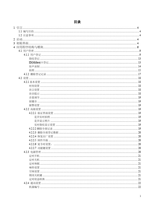
目录1 引言 (4)1.1 编写目的 (4)1.2 注意事项 (4)2 启动 (4)3 初始界面 (4)4 应用程序结构与模块 (6)4.1 用户管理 (9)4.1.1 用户登记 (9)指纹登记 (13)ID(Mifare)卡登记 (13)原声录制 (14)拍照 (15)4.1.2 删除登记记录 (17)4.2 设置 (18)4.2.1基本设置 (18)时间设置 (18)语言设置 (18)语音提示 (18)音量调节 (19)按键音 (19)报警设置 (19)4.2.2 高级设置 (19)4.2.2.1 验证界面设置 (19)是否实时拍照 (19)是否显示照片 (19)实时指纹显示设置 (19)4.2.2.2删除全部记录 (19)4.2.2.3 删除全部登记数据 (20)4.2.2.4 恢复出厂设置 (20)4.2.2.5 固件升级 (20)4.2.2.6 夏令时设置: (20)4.2.2.7 功能键设置 (20)4.2.3 电源管理 (20)定时开机 (21)定时关机 (21)定时休眠 (21)响铃设置 (21)空闲设置 (21)锁闭关机键 (21)定时状态转换 (21)4.2.4 通讯设置 (22)机器编号 (22)RS232 (22)RS485 (22)波特率 (22)以太网 (22)IP地址 (22)子网掩码 (22)网关地址 (22)连接密码 (23)动态IP分配 (23)后台地址 (23)4.2.5 记录设置 (23)管理记录警告(报警) (23)验证记录警告(报警) (23)重复确认时间 (23)4.2.6 自动检测 (23)4.3门禁功能设置 (24)4.3.1 时间段设置 (24)4.3.2 分组功能设置 (25)4.3.3 用户门禁设置 (25)4.3.4 开锁组合设置 (26)开锁组合基本设置 (26)开锁组合设置 (26)4.3.5 锁驱动时长 (28)4.3.6 门磁延时 (28)4.3.7 门磁开关设置 (28)4.3.8 胁迫报警设置 (28)胁迫指纹管理 (28)验密码报警 (28)按键求助 (28)报警延迟 (29)4.3.9 错按报警 (29)4.3.10 反潜功能设置 (29)4.3.11 绑定ID (29)4.4 U盘管理 (29)4.5解除报警 (29)4.6系统信息 (30)4.6.1 用户登记数 (30)4.6.2 指纹登记数 (30)4.6.3 验证记录数 (30)4.6.4 管理记录数 (30)4.6.5 已用内存 (30)4.6.6 剩余容量 (30)4.6.7 设备信息 (30)4.7数据查询 (31)验证记录查询 (31)管理记录查询 (31)用户登记查询 (31)5外接端口连接方式 (31)5.1 外接端口总体描述 (31)5.2 连接说明 (32)5.2.1 RS232连接 (32)5.2.2 RS485连接 (32)5.2.3 出门开关连接 (33)5.2.4 门磁连接 (34)5.2.5 报警连接 (34)5.2.6 电锁连接 (35)5.2.7 电铃连接 (36)5.2.8 指纹读头连接 (37)6组网方式 (37)6.1 分体机组网方式 (38)6.2 一体机组网方式 (38)6.3 指纹读头组网方式 (38)7 终端设备组网调线方式说明 (39)7.1分体机调线连接方式图 (40)7.2一体机调线连接方式图 (41)8 控制器使用说明 (41)8.1 控制器外接端口图说明 (42)8.2 控制器连接说明 (42)8.2.1 出门开关连接 (42)8.2.2 门磁连接 (43)8.2.3 报警器连接 (43)8.2.4 电锁连接 (44)8.2.5 电铃连接 (46)9 基本概念与说明 (47)误判 (47)拒判 (47)权限级别 (47)状态键 (47)消息通知 (47)主从机 (48)夏令时(时区设置) (48)1 引言1.1 编写目的用户使用说明书.1.2 注意事项本考勤机不可阳光直射或强烈阳光下工作。
DC3003A使用说明书

智能位置控制仪(单通道控制器)主要特点:1: 触摸屏操作界面,操作简便2:高速快捷,功能齐备3:拉料速度智能化自动控制4:后放料智能化自动控制使用说明书一:操作界面参数说明:按显示屏中文或英文,进入工作界面工作界面参数说明:A1:计数(COUNT):对所做的产品进行实时计数,当计数值和整本计数相等时,自动清零. A2:补数(SUB): 对当前的计数值进行减数.A3:速度(SPEED):实时显示当前每分钟主机的工作速度A4:长度(LENGTH) :当前所制产品的长度.A5:单批设定(INT):设定每批的数量.A6:色/白(COLOR/WHITE):印刷和空白切换A7:寻标(SEEK):印刷状态时按此键自动寻找色标A8:主机、GK1、GK2、GK3、超速、堵料:工作状态指示A9:通道设置(SET):进入下页设定菜单.A10:点进(FOR):在主机停止的状态下点动进料A11:点退(BACK): 在主机停止的状态下点动退料A12:启动(RUN): 在主机停止的状态下,按此键主机开始工作A13:停止(STOP):在主机运行的状态下,按此键主机停止工作A14:通道设置:包括参数设置、常用参数、通道参数内容B:功能参数说明二:控制器(PLC)接线端接线说明控制器(PLC)8位扩展口接线说明:三:CN1信号接口说明:(25芯插头)信号扩展板接线说明四: 步进电机驱动器接线三相混合式驱动器HB-B3CD (步进驱动器推荐使用600步/转 单脉冲输入)A (驱动器输出) ………………… 七芯电机插头(1#)B (驱动器输出) ………………… 七芯电机插头(3#)C (驱动器输出) ………………… 七芯电机插头(5#)220V : ………………… 交流220V 电源输入 220V : ………………… 交流220V 电源输入说明:如果电机实际方向和要求的相反只需将A 、B 两条电机线对调即可。
五:PLC 连接示意图六: 外接附件1,霍尔开关: 红线:+12V 黑线:-12V 地 黄线或蓝线:信号线(GK1,GK2) 2,色标光电: 红线+12V 黑线:-12V 地 白线或绿线:信号线(GK3) 3,放料光电(接近开关): 红线+12V 黑线:-12V 地 信号线(低电平输出)七:霍尔开关逻辑采样关系图假设磁铁固定轮顺时针方向旋转A轮B轮霍尔1(GK1)霍尔2(GK2)调整步骤:首先做好两个固定轮安装再主机轴上,然后把磁铁按照下面的步骤分别放在固定轮上,固定轮直径大致为60mm。
- 1、下载文档前请自行甄别文档内容的完整性,平台不提供额外的编辑、内容补充、找答案等附加服务。
- 2、"仅部分预览"的文档,不可在线预览部分如存在完整性等问题,可反馈申请退款(可完整预览的文档不适用该条件!)。
- 3、如文档侵犯您的权益,请联系客服反馈,我们会尽快为您处理(人工客服工作时间:9:00-18:30)。
智能位置控制仪
(单通道控制器)
主要特点:1: 触摸屏操作界面,操作简便
2:高速快捷,功能齐备
3:拉料速度智能化自动控制 4:后放料智能化自动控制
使
用
说
明
书
一:操作界面参数说明:
按显示屏中文或英文,进入工作界面
工作界面参数说明:
A1:计数(COUNT):对所做的产品进行实时计数,当计数值和整本计数相等时,自动清零. A2:补数(SUB): 对当前的计数值进行减数.
A3:速度(SPEED):实时显示当前每分钟主机的工作速度
A4:长度(LENGTH) :当前所制产品的长度.
A5:单批设定(INT):设定每批的数量.
A6:色/白(COLOR/WHITE):印刷和空白切换
A7:寻标(SEEK):印刷状态时按此键自动寻找色标
A8:主机、GK1、GK2、GK3、超速、堵料:工作状态指示
A9:通道设置(SET):进入下页设定菜单.
A10:点进(FOR):在主机停止的状态下点动进料
A11:点退(BACK): 在主机停止的状态下点动退料
A12:启动(RUN): 在主机停止的状态下,按此键主机开始工作
A13:停止(STOP):在主机运行的状态下,按此键主机停止工作
A14:通道设置:包括参数设置、常用参数、通道参数内容
B:功能参数说明
二:控制器(PLC)接线端接线说明
注:所有输入,输出信号均为低电平有效! 模拟量要订购时说明才有,否则无此功能!控制器(PLC)8位扩展口接线说明:
三:CN1信号接口说明:(25芯插头)
信号扩展板接线说明
四: 步进电机驱动器接线
三相混合式驱动器 HB-B3CD(步进驱动器推荐使用600步/转单脉冲输入)
A(驱动器输出)…………………七芯电机插头(1#)
B(驱动器输出)…………………七芯电机插头(3#)
C(驱动器输出)…………………七芯电机插头(5#)
220V:…………………交流220V电源输入
220V:…………………交流220V电源输入
说明:如果电机实际方向和要求的相反只需将A、B两条电机线对调即可。
五:PLC连接示意图
六:外接附件
1,霍尔开关:红线:+12V 黑线:-12V地黄线或蓝线:信号线(GK1,GK2)2,色标光电:红线+12V 黑线:-12V地白线或绿线:信号线(GK3)
3,放料光电(接近开关):红线+12V 黑线:-12V地信号线(低电平输出)
七:霍尔开关逻辑采样关系图
假设磁铁固定轮顺时针方向旋转
A轮 B轮
霍尔1(GK1)霍尔2(GK2)
调整步骤:首先做好两个固定轮安装再主机轴上,然后把磁铁按照下面的步骤分别放在固定轮上,固定轮直径大致为60mm。
注意:霍尔开关1对应A,B壹个磁铁,霍尔开关2对应C,D壹个磁铁;首先调整A,B壹个磁铁,然后再调整C,D磁铁。
A为送料开始位置(也做横吹开始位置),即上切刀由最底下往上运动,上移到距离下切刀口1~2CM并且能保证步进电机此时送料膜不会被上切刀堵住的位置。
因A,B为同一块磁铁所以A位置一旦确定B位置自然也确定。
C 为送料停止位置,即上切刀由最底下往上运动到最高点往下回落到与下切刀口正好接触时的位置,D为脱袋翻板位置,也做竖吹延时开始位置。
同理:因C,D为同一块磁铁所以C位置一旦确定D位置自然也确定。
强调:磁铁有正反方向,只有一面起作用。
当所有磁铁位置都调整正确,主机运行后会有实时速度显示。