KNXEIB系统设计手册
KNX-EIB系统介绍(正式发布版)
SCALE:A3 PROJECT NO: DRA WN BY: DATE:April 11, 2013 SHEET:4 of 12
IISFREE
INNOVATION FREE PEOPLE
每个DP(数据点)可以看做是一个回路或者一个按键开关
EIB组地址
0/0/1
总线发送组地址 命令时,引起该 组地址状态改变
0/0/2 3/4/2
DP Datapoints1 Datapoints2
关联DP值 发生改变
Datapoints3
IISFREE场景
共25页,每页10个序号,一共250个,对应250个DP
SCALE:A3 PROJECT NO: DRA WN BY: DATE:April 11, 2013 SHEET:8 of 12
IISFREE
INNOVATION FREE PEOPLE
总线设备属性设定 9
Bus device property set 9
总线设备属性设定 9 Bus device property set 9
举例说明
图示 的设备 为本文 所述接 口协议 模块,由 图可 以看到 ,其具 有250 个DP ,每个 DP 有 14种属 性可以 定义;每个 DP可以 属于任 意 一个 组地址 ;多个 DP可以 对应同 一个组 地 址。唯一 要求是 同一个 组地址 下的DP 属性 必须 相同。
REV ISIO NS
触发相应 场景发出
组地址状态改变
同组DP的值改变
触发相对应序号的场景
组地址状态改变
KNX房间自动化系统说明说明书

Answers for infrastructure.Future-proof and flexible systemfor room automation based on KNXDemand-related lighting/shading control and application-oriented installation of control modules with GAMMA room automation boxHighlightsQ F lexible functionality thanksto a wide choice of modules and flush-mounting devices for lighting and shading controlQ M atching products for alltypes of installations – with regard to individualfunctions and multifunctional applicationsQ S eamless integration intothe most diverse types of systems, thanks to standard-ized KNX communicationQ L ower wiring costs sincepower is supplied via the inte-grated busThe worldwide standard for home and b uildingcontrolFlexibility with regard to functionality The new room automation systemincludes sensors and actuators for light-ing/shading control and for heating, v entilation and cooling systems. Other products are modules for use with the GAMMA room automation box AP 641 and the automation module box AP 118 plus flush-mounting devices with or without mounting frame. So the product range offers devices with identical func-tionality for different types of installation and locations with identical configuration options. What‘s more, the majority of the devices can be combined with HVAC room applications.Matching solutions for every field of useThe amount of available space and i nstallation, wiring and maintenance costs have an impact on the selection of the type and place of installation. So the flush-mounting devices are ideally suited for use with buttons installed close to the function they have to perform, such as blind buttons by the windows. By con-trast, the GAMMA room automation box and the automation module box arep referably used in wide-span offices to be installed in suspended/false ceilings. In addition, they are used in spaces with no access: They can simply be fitted in corridors where they are always accessible for maintenance.Straightforward integration and i nstallationThe sensors and actuators of the new room automation system are fully com-patible KNX devices which – thanks to standardized communication – can be freely combined with other KNX products or can be seamlessly integrated into suit-able systems. Power is supplied via the bus, so there is no need to provide extra power supply. Straightforward installation also extends to wiring. With the new dual push-in terminalsfor single and stranded wires, ferrules are no longer required. These types of wires can therefore be installed fast and without extra effort, allowing straightforward bridging via the dual push-in terminals.Modular system for function-oriented installation of room automationSiemens is the only company marketing a complete range of products for room automation and offering the highest flexibility when it comes to select-ing the type and place of installation.Modular room automation3■OverviewModular room automationA new chapter for GAMMA instabus – decentralized and yet modular room automation with its own KNX components for flexible use in the room, based on one platform – regardless of installation location and type.For surface mounting, for example, in a room or hallway, we recommend the new room automation box, providing space for eight KNX sensor/actuator modules. Moreover, the automation module box further permits the addition of an independent KNX sensor/actuator module close to the actual application, for example, in wall ducts, blind boxes or light housings.Both automation boxes are assembled with RS or RL sensor/actuator modules in a special quick-mount design. The available modules are full KNX bus participants functioning as binary in-puts and outputs, as well as blind actuators, universal dimmer, and switch actuators. The RS and RL modules have the same functionality for flush-mounting actuators as well Identical func-tionality is available for different installation types or locations featuring the same configuration possibilities. As a result, the de-vices use a common application program regardless of mount-ing variant – i.e. devices for installation in the room automation box and automation module box as well as flush-mount with or without mounting frame.Modular room automation4■Technical specificationsTypeRL 260/23RS 510/23RL 512/23RS 520/23RL 521/23RS 525/23Enclosure dataDesignRL RS RL RS RL RS Degree of protectionIP20IP20IP20IP20IP20IP20Modular installation device for mounting in AP 118 automation module box or AP 641 room control box ✔✔✔✔✔✔Dimensions •Heightmm 36.235.536.235.536.235.5•Width/∅ (1 MW = 18 mm)mm 47.850.247.850.247.850.2•Depthmm 86.548.886.548.886.548.8Screwless terminals for the connection and looping through of untreated solid, finely stranded and stranded conductorsmm 20.5 ... 2,50.5 ... 2,50.5 ... 2,50.5 ... 2,50.5 ... 2,50.5 ... 2,5Power supplyElectronics powered over bus voltage✔✔✔✔✔✔Bus connectionIntegrated bus coupling units ✔✔✔✔✔✔Bus connection via bus terminal✔✔✔✔✔✔Type DescriptionAP 118AP 118 automation module boxes•1 slot for a sensor/actor module, type RS or RL•Separate connection compartment and strain relief for bus cable and functional lines•Modular installation device with screw fixing for installation in linking ducts, under raised floors or for surface mounting on the ceiling•Enclosure: Plastic •Degree of protection: IP20•Dimensions (L x W x H): 180 x 50 x 41.1 mmAP 641 AP 641 room control boxes•8 slots for a sensor/actor module, type RS or RL•Internal bus cable for connection of the sensor/actuator module to the bus•Separate connection compartment and strain relief for function-al lines•Two PE/N bars for accommodation of the PE and neutral con-ductor of the functional lines•Bus connection via bus terminal•Modular installation device with screw fixing for installation under raised floors, on the wall or ceiling or in wet rooms •Enclosure: Plastic •Degree of protection: IP54•Dimensions (L x W x H): 300 x 300 x 50 mmRL 260/23RL 260/23 binary inputs 4 inputs for 12 V ... 230 V AC/DC•Max. length of unshielded leads per input: 100 m •The following functions can be selected per input:-Switching state/send binary value -Switch edge/short/long switch-1-button dimming, shading control or group control-1-bit scene control -8-bit scene control -8-bit value edge -8-bit value short/long-16-bit floating-point value edge, short/long-8/16/32-bit pulse counting without/with limit value monitoring•The following functions can be selected per input pair:-2-pushbutton dimming with stop telegram -2-pushbutton shading control•Optional blocking of each input by means of the respective blocking object•Transmission of the input objects after change •Optional cyclic transmission of input objectsModular room automation5RS 510/23RS 510/23 binary output devices2 x 230 V AC,10 A, (resistive load)•Operating mode can be adjusted for each output (normal mode, timer mode)•Relay operating mode can be adjusted for each output (NO contact/NC contact)•Status object can be added for each output •Adjustable ON/OFF delay for each output•Logic operation (AND/OR) of two communication objects for each output•Adjustable switching state in the event of bus voltage failure and recovery for each output•Object for night mode can be added for each output for the time-delayed ON switching of the output (and thus the lighting) at night•Adjustable ON period during night or timer mode•Selectable retripping of ON period (ON-time extension) during timer mode•Selectable warning of impending OFF by turning the device briefly on and off three times (flashing) during night or timer mode•Selectable function: manual override of an output, including ad-ditional communication object•Selectable function: forced control output for positive ON/OFF switching of an output, including additional communication ob-ject•Selectable function: operating hours counting with limit value monitoring of operating hours•Selectable function: switching cycle counting with limit value monitoring of switching operations•Integrated 8-bit scene control and integration of each channel in up to 8 scenesRL 512/23RL 512/23 switch actuators 1 x 230 V AC, 16 AX•One relay contact as switching element•Fluorescent lamp load acc. to EN 60669-1: 16 AX (200 μF) at 230 V AC•Switching current during AC1 operation (p.f. = 0.8) acc. to EN 60947-4-1: 20 A at 230 V AC•Switching current during AC3 operation (p.f. = 0.45) acc. to EN 60947-4-1: 16 A at 230 V AC•Operating mode can be adjusted for each output (normal mode, timer mode)•Relay operating mode can be adjusted for each output (NO contact/NC contact)•Status object can be added for each output •Adjustable ON/OFF delay for each output•Logic operation (AND/OR) of two communication objects for each output•Adjustable switching state in the event of bus voltage failure and recovery for each output•Object for night mode can be added for each output for the time-delayed ON switching of the output (and thus the lighting) at night•Adjustable ON period during night or timer mode •Selectable retripping of ON period (ON-time extension) during timer mode•Selectable warning of impending OFF by turning the device briefly on and off three times(flashing) during night or timer mode•Selectable function: manual override of an output, including additional communication object•Selectable function: forced control output for positive ON/OFF switching of an output, including additional communication object•Selectable function: operating hours counting with limit value monitoring of operating hours•Selectable function: switching cycle counting with limit value monitoring of switching operations•Integrated 8-bit scene control and integration of each channel in up to 8 scenesRL 521/23 RL 521/23 shutter/blind actuators, RS 520/23 shutter/blindactuators •For the control shading, door/window drives with AC motor for 230 V AC and electromechanical or electronic limit switches •Electrically interlocked relays for reversing direction of rotation •Integrated electronics for detecting the response of electrome-chanical limit switches and for autocalibration of travel times from one end position to the other•Communication objects per actuator channel for moving the shading into its end position, for stopping movement or for step-wise adjustment of blind slats•Communication objects for direct movement to a position for shading and blind slats via position specifications as percent-age value (level of precision depends on drive mechanics)•Automatic opening of the blind slats up to a preset position after the shutter/blind has lowered without interruption from the top to the bottom position•Integrated 1-bit scene control to store and retrieve (restore) 2 intermediate positions of shutter/blinds and slats•Integrated 8-bit scene control and integration of each output in up to 8 scenes•Optional object "Sun" for the activation/deactivation of the sun-light tracking control of the blind slats for shading with maxi-mum daylight•Differentiation between automatic and manual mode and auto-matic switchover from manual to manual mode of the relevant actuator channel by pressing a bus pushbutton for the manual control of the respective shading•Priority of manual mode over automatic position commands •Optional central command for switching all channels over to automatic mode and for moving the shading into the top or bot-tom end position•Alarm object "Wind", "Rain" and "Frost" per channel for moving the shading into the configured safety position and with the blocking of movement into a different position for as long as the alarm is pending•Movement-blocking object per device or per channel for lock-ing the shading in its current position (e.g. for cleaning the out-er slats)•Status object per actuator channel for scanning or automatically sending the shading and blind slat position as a percentage value•Optional status object for signaling that the bottom or top posi-tion has been reachedRS 520/23 shutter/blind actuators •1 x 230 V AC, 6 A (resistive load)RL 521/23 shutter/blind actuators •2 x 230 V AC, 6 A (resistive load)RS 520/23TypeDescriptionModular room automation6RS 525/23RS 525/23 universal dimmers1 x 230 V AC, 250 VA•One output for the switching and dimming of resistive, inductive or capacitive loads•Automatic adjustment to leading-edge or trailing-edge phase control, depending on the connected load type•Electronic protection of output against overload, short circuit and overtemperature•Signaling of overloads, short circuits and overtemperature over the bus•Selection of operating mode (normal mode, one or two-stage timer mode, flashing)•Adjustable ON/OFF-delay•Individually adjustable dimming time from 0 % to 100 % for ON/OFF switching and brighter/darker dimming•Two dimming value objects, each with adjustable dimming time of 0 ... 100 %•ON and/or OFF switching of an output via dimming •Adjustable dimming value when switching ON •Start up or dimming of a new dimming value•Status object for switching and/or status object for dimming value can be added•Object for disabling/enabling of output can be added•Optional transmission of status objects on demand and/or auto-matically after modification•Adjustable blocking time for transmission of the status objects after a restart and bus power recovery•Adjustable dimming value after bus voltage failure and recovery and after system recovery•Object for night mode can be added for the time-delayed ON switching of the output (and thus the lighting) at night •Adjustable ON period during night and timer mode•Optional warning of impending OFF by dimming to 50 % of the previous dimming value during night or timer mode•Integrated 8-bit scene control and integration of output in up to 8 scenes•Adjustable dimming time during scene control•Selectable function: operating hours counting with limit value monitoring of operating hours•Selectable function: switching cycle counting with limit value monitoring of switching operationsTypeDescriptionModular room automation*Diese Menge oder ein Vielfaches dieser Menge kann bestellt werden.7■Selection and ordering dataTypeVersionDT Order No.Price per PUPU (UNIT,SET, M)PS*/P . unit PGWeight per PU approx.kg5WG1 118-4AB01AP 118AP 118 automation module boxes A5WG1 118-4AB0111 unit 1390.1001 slot for a sensor/actuator module, type RS or RL5WG1 641-3AB01AP 641AP 641 room control boxes A5WG1 641-3AB0111 unit 1391.2008 slots for a sensor/actuator module, type RS or RL5WG1 260-4AB23RL 260/23RL 260/23 binary inputs 1)A5WG1 260-4AB2311 unit 1390.0604 inputs for 12 ... 230 Vincl. bus connection module5WG1 510-2AB23RS 510/23 RS 510/23 binary output devices 1)A5WG1 510-2AB2311 unit 1390.0452 x 230 V AC, 10 Aincl. bus connection module5WG1 512-4AB23RL 512/23RL 512/23 switch actuators 1)A5WG1 512-4AB2311 unit 1390.0701 x 230 V AC, 16 AXincl. bus connection module5WG1 520-2AB23RS 520/23 RS 520/23 shutter/blind actuators 1)A5WG1 520-2AB2311 unit 1390.0551 x 230 V AC, 6 A (resistive load)incl. bus connection module5WG1 521-4AB23RL 521/23 RL 521/23 shutter/blind actuators 1)A5WG1 521-4AB2311 unit 1390.0702 x 230 V AC, 6 A (resistive load)incl. bus connection module5WG1 525-2AB23RS 525/23 RS 525/23 universal dimmers 1)A5WG1 525-2AB2311 unit 1390.0451 x 230 V AC, 250 VAincl. bus connection module1)The AP 641 room control box and AP 118 automation module box must be ordered separately.Modular room automation8■Technical specificationsTypeUP 510/03UP 510/13UP 520/03UP 520/13UP 525/03UP 525/13Enclosure dataDesignUP UP UPUPUP UPFor installation in flush-mounting switch and socket boxes with ∅ 60mm✔✔✔✔✔✔10-pole BTI socket (BTI - Bus TransceiverInterface) for plugging of bus terminal devices with BTI connector ✔--✔--✔--Dimensions •Heightmm 4241.34241.34241.3•Width/∅ (1 MW = 18 mm)mm 715071507150•Tiefe mm7150.97150.97150.9Screw fixing✔--✔--✔--Power supplyBus-powered electronics✔✔✔✔✔✔Bus connectionIntegrated bus coupling units ✔✔✔✔✔✔Bus connection via bus terminal✔✔✔✔✔✔Output functionsMax. number of group addresses 120120120120120120Max. number of assignments120120120120120120Configurable behavior in the event of a bus volta-ge failure and bus voltage recovery ✔✔✔✔✔✔Scene conIntegrated 8-bit scene control ✔✔✔✔✔✔Scenes to be integrated per channel888888TypBeschreibungUP 510/03UP 510/03 binary output devices, UP 510/13 binary output devices2 x 230 V AC, 10 A (resistive load)•Unchanged switching state of outputs in the event of system voltage failure•Integrated 8-bit scene control, 8 scenes to be integrated per channel •OFF delay •ON delay•Timer mode (automatic stairwell switch)•Night mode (lighting for cleaning)•Warning of impending OFF •Positively driven operation •Logic function (2 objects)•Can be inverted per output (NO contact/NC contact)•Transmitting status per channelUP 510/13UP 520/03UP 520/03 shutter/blind actuators, UP 520/13 shutter/blind actuators1 x 230 V AC, 6 A (resistive load)•Electrically interlocked relays (for reversing direction of rotation)•Modes of operation: Automatic mode for sunlight tracking con-trol, manual mode, standard mode•Status: Transmitting status per channel, status position of shad-ing 8-bit, status position of slats 8-bit•Integrated 1-/8-bit-scene control, 8 scenes to be integrated per channel•Travel lock (e. g. for cleaning the outer shutter/blinds)•Separate raising/lowering protection•Alarm: Move to safety position, locking in this position for as long as alarm is active•Individual configuration of actuator channels•Suitable for integration in a sunlight tracking control system •End position detection•shading control (UP/DOWN) using position data (8-bit value), travel to end position, stopping, stepwise adjustment •Slat control (OPEN/CLOSE) using position data (8-bit value), Travel to end position, stopping, stepwise adjustment UP 520/13UP 525/03UP 525/03 universal dimmers, UP 525/13 universal dimmers1 x 230 V AC, 10 ... 250 VA•Electronic protection of outputs against overload and short circuit•Switching: ON/OFF, Configurable starting value, Blocking object per channel•Dimming: BRIGHTER/DARKER, Adjustable dimming range Minimum dimming value (basic brightness) Maximum dimming value, Dim or startup 8-bit value•Integrated 1-/8-bit-scene control, 8 scenes to be integrated per channel•Status: Transmitting switch and dimming status, Fault indica-tions overload/short circuit/overtemperature on busUP 525/13Modular room automation■Selection and ordering data5WG1 510-2AB035WG1 510-2AB13Shutter/blind actuators5WG1 520-2AB035WG1 520-2AB13Universal dimmers5WG1 525-2AB035WG1 525-2AB13* You can order this quantity or a multiple thereof.9Modular room automation 10Modular room automation11/gamma “We are the trusted technology partner for energy-efficient, safe and secure buildings and infrastructure.”Answers for infrastructure.Our world is undergoing changes that force us to think in new ways: demographic change, urbanization, global warming and resource shortages. Maximum efficiency has top priority – and not only where energy is concerned.In addition, we need to increase comfort for the well-being of users. Also, our need for safety and security is constantly growing. For our customers, success is defined by how well they manage these challenges. Siemens has the answers.Siemens Switzerland LtdInfrastructure & Cities SectorBuilding Technologies DivisionInternational HeadquartersGubelstrasse 226301 ZugSwitzerlandTel +41 41 724 24 24Siemens Building TechnologiesInfrastructure & Cities SectorBrunel HouseSir William Siemens Square, FrimleyCamberleySurrey, GU16 8QDUnited KingdomTel +44 1276 696000Siemens LtdInfrastructure & Cities SectorBuilding Technologies Division22/F, Two Landmark East100 How Ming Street, Kwun TongKowloon, Hong KongTel +852 2870 7888。
KNX 技术手册 ABB-i-Bus-KNX Millenium说明书

12.2012KNX 技术手册ABB-i-Bus®-KNX Millenium多功能操作元件(包括 BAU)1/2 倍6125/20-981-500AMD72053-AN2/4 倍6126/20-981-500AMD74053-AN3/6 倍6129/20-981-500AMD76053-AN3/6 倍带 IR6129/21-981-500AMD76153-AN1手册提示 (3)1.1一般提示 (3)1.2手册结构 (3)1.3手册中的标志 (4)2安全提示 (5)2.1按规定使用 (5)2.2未按规定使用 (5)2.3目标群和资质 (6)2.4责任和保修 (6)2.5环境 (6)3结构与功能 (7)3.1功能和装备特征 (7)3.2设备概览 (8)3.2.1正面 (8)3.2.2背面 (8)3.2.3正面,无操作元件盖板 (8)3.3盖板框和支撑环 (9)4技术数据 (10)5连接图和尺寸图 (10)5.1连接图 (10)5.2尺寸图 (10)6安装和电气连接 (11)6.1对装配人员的要求 (11)6.2安装 (12)6.2.1安装设备 (12)6.3操作按键更换 (14)6.4电气连接 (16)7调试 (17)7.1软件 (17)7.1.1准备工作步骤 (17)7.1.2分配物理地址 (17)7.1.3分配组地址 (18)7.1.4选择应用程序 (18)7.1.5区分应用程序 (18)8操作 (19)8.1操作按键 (19)8.2LED 颜色方案 (20)8.3带有红外线接收器的 3-6 倍操作元件 (20)9清洁 (20)10保养 (20)1 手册提示1.1 一般提示仔细通读本手册并遵守所有列出的提示,从而确保产品的安全运行和长效的使用寿命。
为了确保条理清晰,本手册并未包含各个产品型号的所有详细信息,可能也未涉及有关安装、运行和维修的每种可能情况。
如需更多信息,或出现手册中未涉及的问题时,可从制造商处索取必需的信息。
施耐德电气KNXEIB智能灯光控制系统介绍

描述
4路干点输入模块 8路干点输入模块 4路24V信号输入模块 8路24V信号输入模块 4路230V信号输入模块 8路230V信号输入模块 2路通用输入/输出接口 4路通用输入/输出接口 4路模拟输入模块 4路模拟输出模块
Schneider Electric - ISC Marketing - 1/2010
●系统集成商
● 在70个国家有30000个系统集成商。 ● 专用调试ETS软件
Schneider Electric - ISC Marketing - 1/2010
6
KNX会员
Schneider Electric - ISC Marketing - 1/2010
7
系统介绍
一个包容的科技…
智能面板带遥控 多功能带温控面板 移动感应器 光线感应器 气象感应器
1.0.0
Area 1
LK15
1.15.0
1.1.1
1.15.1
Linie 1
1.1.63 Linie 15
1.15.63
Area line 0.0
15 14 13 12 11 10 9 8 7 6 5 4 3 2
一个系统包括15个域
整个系统总共的设备数可达 14400个
Schneider Electric - ISC Marketing - 1/2010
描述
4路10A开关控制模块 8路10A开关控制模块 12路10A开关控制模块 2路16A开关控制模块 4路16A开关控制模块 8路16A开关控制模块 12路16A开关控制模块 2路16A开关控制模块带电流检测 4路16A开关控制模块带电流检测 8路16A开关控制模块带电流检测 12路16A开关控制模4 2.5 4
施耐德KNX、EIB设计手册

2012
KNX /EIB 系统
第一章KNX/EIB系统简介/2第二章KNX/EIB系统设计例图/6第三章KNX/EIB系统与BA的连接方法/10第四章KNX/EIB系统施工说明/11第五章KNX/EIB系统元件一览表/12第六章KNX/EIB系统部分业绩/21
2
3
4
Tree
5
6
7
2、通过USB接口进行连接。
二、通过USB接口进行连接:
KNX/EIB系统提供USB接口与BA系统连接,接口协议为KNX/EIB标准协议,应用软件可由BA系统集成商自行开发。
此方法可实现施耐德KNX/EIB系统系统与BA系统的完全连接,但要求BA系统集成商有一定的软件开发能力。
USB接口元件型号:MTN681829
2、软件OPC-Server,安装OPC-Server软件的电脑通过USB接口与KNX/EIB系统连接,BA可以OPC方式访问Server。
此方式成本相对较低
3、KNX/EIB适配器,提供USB接口及文本方式的数据。
KNX通用接口用户手册
因此在本产品报废后,请联系当地的相关垃圾回收处理部门,以确保本产品能进入正确的
废旧处理程序。
1 技术参数
供电特性 输入/输出
KNX-BUS 总线供电 供电电流 功耗 通道数 输入电压/电流 输出电压/电流
2
3 外观、尺寸和应用连线图
3.1 外观
1 KNX 总线接口 2 设备编程按键 3 输入/输出接线端子 4 编程指示灯(红色)
3.2 尺寸 48.00 mm
41.50 mm
19.00 mm
3
3.3 应用连线图 3.3.1 输入控制
4
3.3.2 输出控制
当本产品用作输出控制时,一端接通道 A~F,另一端接电源负端。每一通道内部串联 1K 的限流电阻,能输出最大电压是 3.3V,最大电流 2mA。
5
4 联系方式
珠海世讯科技有限责任公司 中国·广东·珠海市高新技术开发区软件园路1号·南方软件园B1栋3 层 TEL:0086-756-3628171/3628181 FAX:0086-756-2612730
外部连接
EIB/KNX总线 输入/输出接线
操作和显示界面 外壳防护等级 安全等级 绝缘隔离 KNX安全电压
温度范围
环境要求
机械参数
外观 认证 CE规范 EMC指标
编程按键 编程指示灯 IP20\隐藏式散热通道 II 过电压 电网污染 SELV 工作温度 长期存储温度 运输中温度 最大空气湿度 体积 重量 安装 灰白、PVC面板 KNX EN50090-1\-2 参见附录 参见附录
指标名称
绝缘强度试验 阻燃试验 温升试验
西门子instabus KNXEIB系统
希思罗(Heathrow)国际机场数字照明设计方案英国希思罗(Heathrow)国际机场,是世界最大的机场之一。
其T5航站楼工程总投资金额42亿英磅,是现今英国最大的基础建筑项目,主体包括一座核心候机楼与两个用高速链路相连接的卫星楼。
航站楼的主候机楼,两个卫星楼,公共通道、电梯前室以及交通中心候车、停车、公共卫生间等公共部位照明以及广告、标识装饰等照明,均采用西门子instabus KNX/EIB系统实现照明控制。
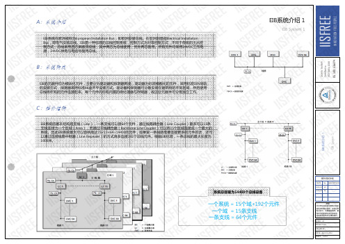
系统简介1.西门子instabus KNX/EIB系统KNX是一个分布式现场总线标准,其拓扑结构包括:线路(Line)、区域(Area)以及系统(System)。
线路(Line)是最小的组成单元,每条线路最多64个设备,每个区域(Area)最多15条线路,而每个系统最多15个区域。
随着网络技术和局域网(LAN)的普及,KNX标准中提出了EIBnet/IP的概念,通过EIBnet/IP协议,KNX总线可以直接与TCP/IP系统连接,总线信号可以在高速以太网上传输。
EIBnet/IP协议的出现,使得系统的扩展不再受传输距离的影响,而数据的传输量和传输速度也不再成为KNX系统的问题。
西门子instabus KNX/EIB系统是基于KNX标准的全分布总线系统,最大的优点在于其控制的灵活、功能的强大及系统的可塑性。
选择不同的模块化设备,通过积木式的不同组合就可以实现各种功能控制,同时挂在总线上的设备运行相互独立,系统的改造和扩展就变得非常容易了。
2.DALI数字可寻址灯光接口现代建筑照明中,荧光灯的使用相当普及。
随着人们对光环境要求的提高,荧光灯的控制也从简单的开关发展到亮度的调节,而荧光灯调光控制方法又取决于电子镇流器技术。
于是从1984年Philips首先推出第一个商业系列电子镇流器以来,电子镇流器的技术获得了飞速的发展。
从1-10V模拟量接口电子镇流器,到数字信号接口(DSI)电子镇流器,以及最新的DALI数字式可寻址灯光接口镇流器,荧光灯的调光方式已完成了模拟量控制向数字化控制的飞跃。
KNX EIB 电源供应器说明说明书
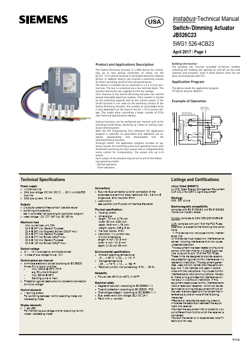
Product and Applications DescriptionThe Switch-/Dimming Actuator is a KNX device for control-ling up to two groups (channels) of lamps via theDC 0/1 -10 V control terminal of dimmable electronic ballasts(ECGs). In addition there is per channel a switching contactfor direct switching on/off of the connected lamps.The device is installed into or attached to a 4 x 4 inch junc-tion box. The bus is connected via a bus terminal block. Theactuator electronics are supplied via the bus voltage.Each channel of the Switch-/Dimming Actuator can controlseveral dimmable electronic ballasts. Their number is limitedby the switching capacity and by the control power. If theon/off function is not used via the switching contact of theSwitch-/Dimming Actuator, the number of controllable ECGsis only dependent on the load of the DC 1-10 V control volt-age. This might allow controlling a larger number of ECGs(see Technical Specifications below).Various functions can be configured per channel such as forswitching on/off lamps, dimming up / down or setting a par-ticular dimming level.With the ETS (Engineering Tool Software) the applicationprogram is selected, its parameters and addresses are as-signed appropriately and downloaded into theSwitch/Dimming Actuator.Amongst others, the application program includes an op-tional counter for switching cycles and operating hours withthreshold monitoring for each output and an integrated 8-bitscene control for incorporating the output into up to 8scenes.Each output of the actuator may be set to one of the follow-ing operating modes:- Normal operation- Timer operationBuilding sitThe buildinswitching thswitches anbeen commApplicatiThe device n“07 B0 A2ExampleP.T.O.ng site functionuilding site function provided ex-factory enablesing the building site lighting on and off via bus walles and actuators, even if these devices have not yetommissioned with ETS.lication Programvice needs the application program2 Dimmer 983C01”.mple of OperationL1V30425157A - DS02instabus ®Technical ManualSwitch-/Dimming Actuator JB526C235WG1 526-4CB23April 2017 / Page 2Location and Function of the Interface ElementsA4A5A6A7A1A2A7A3A3A7A8A9A10A11A13A12A1Type label (with space for physical address of the ac-tuator)A2Identification number of the device A3Protective lid over bus connectionA4Bus connection terminal block for single core conduc-tors with 0.6...0.8 mm ØA5LED for indicating normal operating mode (LED off) or addressing mode (LED on); returns to normal operating mode automatically after receiving the physical address A6Learning button for switching between normal operat-ing mode and addressing mode and for receiving the physical address A71/2 inch screw nut A8Wire (red) Load A (AWG #12)A9Wire (black) Line (Hot)(AWG #12)A10Wire (yellow) Load B (AWG #12)A11Wire (grey) DIM Common (AWG #18)A12Wire (purple) DIM A (AWG #18)A13Wire (blue) DIM B (AWG #18)Dimension DiagramDimensions in mm (inch)(2.76)(2.76)(3.54)(1.76).B1B4B2B1B3B1B4B2B3B14” x 4” Junction Box B2DeviceB3Bus connection pins of the module for connection of the bus terminal block for single core conductors with 0.6…0.8 mm ØB41/2 inch screw nutMounting and Dismounting∂Mounting of a JB module:Option 1 (mounting inside a J-Box)- Insert the thread of the JB module (B2) into the 1/2 inch knockout between two adjacent J-Boxes (B1)- Fasten the JB module (B2) with the 1/2 inch thread nut (B4)- Remove the protective lid (B3) and connect the bus wire to the bus terminal block (A4)- Connect the wires from the device to the field wires using wire nuts (not provided in package)Option 2 (mounting outside of a J-Box)- Insert the thread of the JB module (B2) into the 1/2 inch knockout of the J-Box (B1)- Fasten the JB module (B2) with the 1/2 inch thread nut (B4)to the J-Box (B1)- Connect the bus wire to the bus terminal block under the protective cover (B3)- Connect the wires from the device to the field wires using wire nuts (not provided in package)∂Assignment of the Physical Address:- A short push (< 2 s) of learning button (A6) enables the ad-dressing mode, which is indicated when the LED is continu-ously on (A5). The device returns to normal operating mode (LED Off) automatically after receiving the physical address or if the learning button is pushed again.- A very long push (> 20 s) of the learning button resets the device to factory settings. This is indicated by constant flash-ing for 8 seconds.- A long push (> 5 s up to 20 s) of the learning button ena-bles the Connection Test for commissioning with Desigo.This mode can be disabled by a short push any time.- Install the protective lid (B3) and fasten with screws (pro-vided in package)∂Dismounting a JB module:- Disconnect power to the module- Remove the wire nuts and bus connection- Unfasten the 1/2 inch thread nut (B4) connecting the JB module (B2) to the J-Box (B1)- Remove the JB module (B2) from the J-Box (B1)D2.4WiringBus connectionSlipping off/on bus connection blocksThe bus connection block consists of two components (C2.1and C2.2) with four terminal contacts each. Take care not to damage the two test sockets (C2.3) by accidentally connect-ing them to the bus cable or with the screw driver (e.g.when attempting to unplug the bus connection block).Slipping off bus connection blocks- Carefully put the screw driver to the wire insertion slit of the bus connection block’s grey component (C2.2)and- pull the bus connection block (C2) from the module.NoteDon’t try to remove the bus connection block from the bot-tom side. There is a risk of shorting-out the device!Slipping on bus connection blocks- Slip the bus connection block (C2) onto the guide slot of the module and- press the bus connection block (C2) down to the stop.Connecting and Disconnecting bus cables Connecting bus cables- The bus connection block (D2) can be used with single core conductors Ø 0.6…0.8 mm.- Remove approx. 5 mm of insulation from the conductor (D1) and plug it into the bus connection block (D2)(red = +, grey = -)Disconnecting bus cables- Unplug the bus connection block (D2) and remove the bus cable conductor (D1) while simultaneously wiggling it.Connecting mains and load circuit:Connect wires-Connect wire leads using wire nuts.。