CONTRONIX说明书
Tektronix 输入RC时常常规化器说明书

I
I
___ ,I
Values are fixed unless marked Variable.
TEKTRONIX SERIAL/MODENLO.
CKT. NO. PARTNO.
EFF
DISC
DESCRIPTION
Cl
281-0060-00
C2
281-0508-00
Capacitors
2-8 pF, Var Cer
12 pF
Cer
500 V
5%
Rl
323-0481-00
Resistor
1 Mn
1/2 W Pree
1%
4
B_
Input Normalizers are not intended to be used to determine whether input capacitance is within certain. limits, or whether the RC product of input resistance and input capacitance is within certain limits. Therefore, they are not intended to be measurement Standards. Furthermore, it is not advisable to attempt to maintain the input capacitance or the input RC time constant on different scopes to tight tolerances with the hope of obviating the need to check or adjust a probe when it is used with a different oscilloscope. Proper probe adjustment' should always be checked each time a probe is connected to a different oscilloscope or plug-in unit. When this practice is
Tektronix MDO3000 Series 数字多功能作业仪用户指南说明书
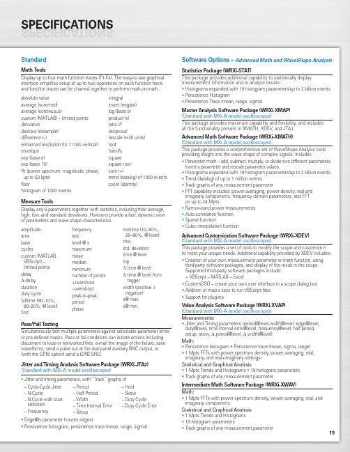
19StandardMath ToolsDisplay up to four math function traces (F1-F4). The easy-to-use graphical interface simplifies setup of up to two operations on each function trace;and function traces can be chained together to perform math-on-math.absolute value integralaverage (summed)invert (negate)average (continuous)log (base e)custom (MATLAB) – limited points product (x)derivativeratio (/)deskew (resample)reciprocaldifference (–)rescale (with units)enhanced resolution (to 11 bits vertical)roof envelope (sinx)/x exp (base e)square exp (base 10)square root fft (power spectrum, magnitude, phase,sum (+)up to 50 kpts) trend (datalog) of 1000 events floorzoom (identity)histogram of 1000 eventsMeasure ToolsDisplay any 6 parameters together with statistics, including their average,high, low, and standard deviations. Histicons provide a fast, dynamic view of parameters and wave-shape characteristics.Pass/Fail TestingSimultaneously test multiple parameters against selectable parameter limits or pre-defined masks. Pass or fail conditions can initiate actions including document to local or networked files, e-mail the image of the failure, save waveforms, send a pulse out at the rear panel auxiliary BNC output, or (with the GPIB option) send a GPIB SRQ.Jitter and Timing Analysis Software Package (WRXi-JTA2)(Standard with MXi-A model oscilloscopes)•Jitter and timing parameters, with “Track”graphs of •Edge@lv parameter (counts edges)• Persistence histogram, persistence trace (mean, range, sigma)Software Options –Advanced Math and WaveShape AnalysisStatistics Package (WRXi-STAT)This package provides additional capability to statistically display measurement information and to analyze results:• Histograms expanded with 19 histogram parameters/up to 2 billion events.• Persistence Histogram• Persistence Trace (mean, range, sigma)Master Analysis Software Package (WRXi-XMAP)(Standard with MXi-A model oscilloscopes)This package provides maximum capability and flexibility, and includes all the functionality present in XMATH, XDEV, and JTA2.Advanced Math Software Package (WRXi-XMATH)(Standard with MXi-A model oscilloscopes)This package provides a comprehensive set of WaveShape Analysis tools providing insight into the wave shape of complex signals. Includes:•Parameter math – add, subtract, multiply, or divide two different parameters.Invert a parameter and rescale parameter values.•Histograms expanded with 19 histogram parameters/up to 2 billion events.•Trend (datalog) of up to 1 million events•Track graphs of any measurement parameter•FFT capability includes: power averaging, power density, real and imaginary components, frequency domain parameters, and FFT on up to 24 Mpts.•Narrow-band power measurements •Auto-correlation function •Sparse function• Cubic interpolation functionAdvanced Customization Software Package (WRXi-XDEV)(Standard with MXi-A model oscilloscopes)This package provides a set of tools to modify the scope and customize it to meet your unique needs. Additional capability provided by XDEV includes:•Creation of your own measurement parameter or math function, using third-party software packages, and display of the result in the scope. Supported third-party software packages include:– VBScript – MATLAB – Excel•CustomDSO – create your own user interface in a scope dialog box.• Addition of macro keys to run VBScript files •Support for plug-insValue Analysis Software Package (WRXi-XVAP)(Standard with MXi-A model oscilloscopes)Measurements:•Jitter and Timing parameters (period@level,width@level, edge@level,duty@level, time interval error@level, frequency@level, half period, setup, skew, Δ period@level, Δ width@level).Math:•Persistence histogram •Persistence trace (mean, sigma, range)•1 Mpts FFTs with power spectrum density, power averaging, real, imaginary, and real+imaginary settings)Statistical and Graphical Analysis•1 Mpts Trends and Histograms •19 histogram parameters •Track graphs of any measurement parameterIntermediate Math Software Package (WRXi-XWAV)Math:•1 Mpts FFTs with power spectrum density, power averaging, real, and imaginary componentsStatistical and Graphical Analysis •1 Mpts Trends and Histograms •19 histogram parameters•Track graphs of any measurement parameteramplitude area base cyclescustom (MATLAB,VBScript) –limited points delay Δdelay duration duty cyclefalltime (90–10%, 80–20%, @ level)firstfrequency lastlevel @ x maximum mean median minimumnumber of points +overshoot –overshoot peak-to-peak period phaserisetime (10–90%, 20–80%, @ level)rmsstd. deviation time @ level topΔ time @ levelΔ time @ level from triggerwidth (positive + negative)x@ max.x@ min.– Cycle-Cycle Jitter – N-Cycle– N-Cycle with start selection – Frequency– Period – Half Period – Width– Time Interval Error – Setup– Hold – Skew– Duty Cycle– Duty Cycle Error20WaveRunner WaveRunner WaveRunner WaveRunner WaveRunner 44Xi-A64Xi-A62Xi-A104Xi-A204Xi-AVertical System44MXi-A64MXi-A104MXi-A204MXi-ANominal Analog Bandwidth 400 MHz600 MHz600 MHz 1 GHz 2 GHz@ 50 Ω, 10 mV–1 V/divRise Time (Typical)875 ps500 ps500 ps300 ps180 psInput Channels44244Bandwidth Limiters20 MHz; 200 MHzInput Impedance 1 MΩ||16 pF or 50 Ω 1 MΩ||20 pF or 50 ΩInput Coupling50 Ω: DC, 1 MΩ: AC, DC, GNDMaximum Input Voltage50 Ω: 5 V rms, 1 MΩ: 400 V max.50 Ω: 5 V rms, 1 MΩ: 250 V max.(DC + Peak AC ≤ 5 kHz)(DC + Peak AC ≤ 10 kHz)Vertical Resolution8 bits; up to 11 with enhanced resolution (ERES)Sensitivity50 Ω: 2 mV/div–1 V/div fully variable; 1 MΩ: 2 mV–10 V/div fully variableDC Gain Accuracy±1.0% of full scale (typical); ±1.5% of full scale, ≥ 10 mV/div (warranted)Offset Range50 Ω: ±1 V @ 2–98 mV/div, ±10 V @ 100 mV/div–1 V/div; 50Ω:±400mV@2–4.95mV/div,±1V@5–99mv/div,1 M Ω: ±1 V @ 2–98 mV/div, ±10 V @ 100 mV/div–1 V/div,±10 V @ 100 mV–1 V/div±**********/div–10V/div 1 M Ω: ±400 mV @ 2–4.95 mV/div, ±1 V @5–99 mV/div, ±10 V @ 100 mV–1 V/div,±*********–10V/divInput Connector ProBus/BNCTimebase SystemTimebases Internal timebase common to all input channels; an external clock may be applied at the auxiliary inputTime/Division Range Real time: 200 ps/div–10 s/div, RIS mode: 200 ps/div to 10 ns/div, Roll mode: up to 1,000 s/divClock Accuracy≤ 5 ppm @ 25 °C (typical) (≤ 10 ppm @ 5–40 °C)Sample Rate and Delay Time Accuracy Equal to Clock AccuracyChannel to Channel Deskew Range±9 x time/div setting, 100 ms max., each channelExternal Sample Clock DC to 600 MHz; (DC to 1 GHz for 104Xi-A/104MXi-A and 204Xi-A/204MXi-A) 50 Ω, (limited BW in 1 MΩ),BNC input, limited to 2 Ch operation (1 Ch in 62Xi-A), (minimum rise time and amplitude requirements applyat low frequencies)Roll Mode User selectable at ≥ 500 ms/div and ≤100 kS/s44Xi-A64Xi-A62Xi-A104Xi-A204Xi-A Acquisition System44MXi-A64MXi-A104MXi-A204MXi-ASingle-Shot Sample Rate/Ch 5 GS/sInterleaved Sample Rate (2 Ch) 5 GS/s10 GS/s10 GS/s10 GS/s10 GS/sRandom Interleaved Sampling (RIS)200 GS/sRIS Mode User selectable from 200 ps/div to 10 ns/div User selectable from 100 ps/div to 10 ns/div Trigger Rate (Maximum) 1,250,000 waveforms/secondSequence Time Stamp Resolution 1 nsMinimum Time Between 800 nsSequential SegmentsAcquisition Memory Options Max. Acquisition Points (4 Ch/2 Ch, 2 Ch/1 Ch in 62Xi-A)Segments (Sequence Mode)Standard12.5M/25M10,00044Xi-A64Xi-A62Xi-A104Xi-A204Xi-A Acquisition Processing44MXi-A64MXi-A104MXi-A204MXi-ATime Resolution (min, Single-shot)200 ps (5 GS/s)100 ps (10 GS/s)100 ps (10 GS/s)100 ps (10 GS/s)100 ps (10 GS/s) Averaging Summed and continuous averaging to 1 million sweepsERES From 8.5 to 11 bits vertical resolutionEnvelope (Extrema)Envelope, floor, or roof for up to 1 million sweepsInterpolation Linear or (Sinx)/xTrigger SystemTrigger Modes Normal, Auto, Single, StopSources Any input channel, External, Ext/10, or Line; slope and level unique to each source, except LineTrigger Coupling DC, AC (typically 7.5 Hz), HF Reject, LF RejectPre-trigger Delay 0–100% of memory size (adjustable in 1% increments, or 100 ns)Post-trigger Delay Up to 10,000 divisions in real time mode, limited at slower time/div settings in roll modeHold-off 1 ns to 20 s or 1 to 1,000,000,000 events21WaveRunner WaveRunner WaveRunner WaveRunner WaveRunner 44Xi-A 64Xi-A 62Xi-A104Xi-A 204Xi-A Trigger System (cont’d)44MXi-A64MXi-A104MXi-A204MXi-AInternal Trigger Level Range ±4.1 div from center (typical)Trigger and Interpolator Jitter≤ 3 ps rms (typical)Trigger Sensitivity with Edge Trigger 2 div @ < 400 MHz 2 div @ < 600 MHz 2 div @ < 600 MHz 2 div @ < 1 GHz 2 div @ < 2 GHz (Ch 1–4 + external, DC, AC, and 1 div @ < 200 MHz 1 div @ < 200 MHz 1 div @ < 200 MHz 1 div @ < 200 MHz 1 div @ < 200 MHz LFrej coupling)Max. Trigger Frequency with400 MHz 600 MHz 600 MHz 1 GHz2 GHzSMART Trigger™ (Ch 1–4 + external)@ ≥ 10 mV@ ≥ 10 mV@ ≥ 10 mV@ ≥ 10 mV@ ≥ 10 mVExternal Trigger RangeEXT/10 ±4 V; EXT ±400 mVBasic TriggersEdgeTriggers when signal meets slope (positive, negative, either, or Window) and level conditionTV-Composite VideoT riggers NTSC or PAL with selectable line and field; HDTV (720p, 1080i, 1080p) with selectable frame rate (50 or 60 Hz)and Line; or CUSTOM with selectable Fields (1–8), Lines (up to 2000), Frame Rates (25, 30, 50, or 60 Hz), Interlacing (1:1, 2:1, 4:1, 8:1), or Synch Pulse Slope (Positive or Negative)SMART TriggersState or Edge Qualified Triggers on any input source only if a defined state or edge occurred on another input source.Delay between sources is selectable by time or eventsQualified First In Sequence acquisition mode, triggers repeatedly on event B only if a defined pattern, state, or edge (event A) is satisfied in the first segment of the acquisition. Delay between sources is selectable by time or events Dropout Triggers if signal drops out for longer than selected time between 1 ns and 20 s.PatternLogic combination (AND, NAND, OR, NOR) of 5 inputs (4 channels and external trigger input – 2 Ch+EXT on WaveRunner 62Xi-A). Each source can be high, low, or don’t care. The High and Low level can be selected independently. Triggers at start or end of the patternSMART Triggers with Exclusion TechnologyGlitch and Pulse Width Triggers on positive or negative glitches with widths selectable from 500 ps to 20 s or on intermittent faults (subject to bandwidth limit of oscilloscope)Signal or Pattern IntervalTriggers on intervals selectable between 1 ns and 20 sTimeout (State/Edge Qualified)Triggers on any source if a given state (or transition edge) has occurred on another source.Delay between sources is 1 ns to 20 s, or 1 to 99,999,999 eventsRuntTrigger on positive or negative runts defined by two voltage limits and two time limits. Select between 1 ns and 20 sSlew RateTrigger on edge rates. Select limits for dV, dt, and slope. Select edge limits between 1 ns and 20 s Exclusion TriggeringTrigger on intermittent faults by specifying the normal width or periodLeCroy WaveStream Fast Viewing ModeIntensity256 Intensity Levels, 1–100% adjustable via front panel control Number of Channels up to 4 simultaneouslyMax Sampling Rate5 GS/s (10 GS/s for WR 62Xi-A, 64Xi-A/64MXi-A,104Xi-A/104MXi-A, 204Xi-A/204MXi-A in interleaved mode)Waveforms/second (continuous)Up to 20,000 waveforms/secondOperationFront panel toggle between normal real-time mode and LeCroy WaveStream Fast Viewing modeAutomatic SetupAuto SetupAutomatically sets timebase, trigger, and sensitivity to display a wide range of repetitive signalsVertical Find ScaleAutomatically sets the vertical sensitivity and offset for the selected channels to display a waveform with maximum dynamic range44Xi-A 64Xi-A 62Xi-A104Xi-A 204Xi-A Probes44MXi-A 64MXi-A104MXi-A 204MXi-AProbesOne Passive probe per channel; Optional passive and active probes available Probe System; ProBus Automatically detects and supports a variety of compatible probes Scale FactorsAutomatically or manually selected, depending on probe usedColor Waveform DisplayTypeColor 10.4" flat-panel TFT-LCD with high resolution touch screenResolutionSVGA; 800 x 600 pixels; maximum external monitor output resolution of 2048 x 1536 pixelsNumber of Traces Display a maximum of 8 traces. Simultaneously display channel, zoom, memory, and math traces Grid StylesAuto, Single, Dual, Quad, Octal, XY , Single + XY , Dual + XY Waveform StylesSample dots joined or dots only in real-time mode22Zoom Expansion TracesDisplay up to 4 Zoom/Math traces with 16 bits/data pointInternal Waveform MemoryM1, M2, M3, M4 Internal Waveform Memory (store full-length waveform with 16 bits/data point) or store to any number of files limited only by data storage mediaSetup StorageFront Panel and Instrument StatusStore to the internal hard drive, over the network, or to a USB-connected peripheral deviceInterfaceRemote ControlVia Windows Automation, or via LeCroy Remote Command Set Network Communication Standard VXI-11 or VICP , LXI Class C Compliant GPIB Port (Accessory)Supports IEEE – 488.2Ethernet Port 10/100/1000Base-T Ethernet interface (RJ-45 connector)USB Ports5 USB 2.0 ports (one on front of instrument) supports Windows-compatible devices External Monitor Port Standard 15-pin D-Type SVGA-compatible DB-15; connect a second monitor to use extended desktop display mode with XGA resolution Serial PortDB-9 RS-232 port (not for remote oscilloscope control)44Xi-A 64Xi-A 62Xi-A104Xi-A 204Xi-A Auxiliary Input44MXi-A 64MXi-A104MXi-A 204MXi-ASignal Types Selected from External Trigger or External Clock input on front panel Coupling50 Ω: DC, 1 M Ω: AC, DC, GND Maximum Input Voltage50 Ω: 5 V rms , 1 M Ω: 400 V max.50 Ω: 5 V rms , 1 M Ω: 250 V max. (DC + Peak AC ≤ 5 kHz)(DC + Peak AC ≤ 10 kHz)Auxiliary OutputSignal TypeTrigger Enabled, Trigger Output. Pass/Fail, or Off Output Level TTL, ≈3.3 VConnector TypeBNC, located on rear panelGeneralAuto Calibration Ensures specified DC and timing accuracy is maintained for 1 year minimumCalibratorOutput available on front panel connector provides a variety of signals for probe calibration and compensationPower Requirements90–264 V rms at 50/60 Hz; 115 V rms (±10%) at 400 Hz, Automatic AC Voltage SelectionInstallation Category: 300 V CAT II; Max. Power Consumption: 340 VA/340 W; 290 VA/290 W for WaveRunner 62Xi-AEnvironmentalTemperature: Operating+5 °C to +40 °C Temperature: Non-Operating -20 °C to +60 °CHumidity: Operating Maximum relative humidity 80% for temperatures up to 31 °C decreasing linearly to 50% relative humidity at 40 °CHumidity: Non-Operating 5% to 95% RH (non-condensing) as tested per MIL-PRF-28800F Altitude: OperatingUp to 3,048 m (10,000 ft.) @ ≤ 25 °C Altitude: Non-OperatingUp to 12,190 m (40,000 ft.)PhysicalDimensions (HWD)260 mm x 340 mm x 152 mm Excluding accessories and projections (10.25" x 13.4" x 6")Net Weight7.26kg. (16.0lbs.)CertificationsCE Compliant, UL and cUL listed; Conforms to EN 61326, EN 61010-1, UL 61010-1 2nd Edition, and CSA C22.2 No. 61010-1-04Warranty and Service3-year warranty; calibration recommended annually. Optional service programs include extended warranty, upgrades, calibration, and customization services23Product DescriptionProduct CodeWaveRunner Xi-A Series Oscilloscopes2 GHz, 4 Ch, 5 GS/s, 12.5 Mpts/ChWaveRunner 204Xi-A(10 GS/s, 25 Mpts/Ch in interleaved mode)with 10.4" Color Touch Screen Display 1 GHz, 4 Ch, 5 GS/s, 12.5 Mpts/ChWaveRunner 104Xi-A(10 GS/s, 25 Mpts/Ch in interleaved mode)with 10.4" Color Touch Screen Display 600 MHz, 4 Ch, 5 GS/s, 12.5 Mpts/Ch WaveRunner 64Xi-A(10 GS/s, 25 Mpts/Ch in interleaved mode)with 10.4" Color Touch Screen Display 600 MHz, 2 Ch, 5 GS/s, 12.5 Mpts/Ch WaveRunner 62Xi-A(10 GS/s, 25 Mpts/Ch in interleaved mode)with 10.4" Color Touch Screen Display 400 MHz, 4 Ch, 5 GS/s, 12.5 Mpts/Ch WaveRunner 44Xi-A(25 Mpts/Ch in interleaved mode)with 10.4" Color Touch Screen DisplayWaveRunner MXi-A Series Oscilloscopes2 GHz, 4 Ch, 5 GS/s, 12.5 Mpts/ChWaveRunner 204MXi-A(10 GS/s, 25 Mpts/Ch in Interleaved Mode)with 10.4" Color Touch Screen Display 1 GHz, 4 Ch, 5 GS/s, 12.5 Mpts/ChWaveRunner 104MXi-A(10 GS/s, 25 Mpts/Ch in Interleaved Mode)with 10.4" Color Touch Screen Display 600 MHz, 4 Ch, 5 GS/s, 12.5 Mpts/Ch WaveRunner 64MXi-A(10 GS/s, 25 Mpts/Ch in Interleaved Mode)with 10.4" Color Touch Screen Display 400 MHz, 4 Ch, 5 GS/s, 12.5 Mpts/Ch WaveRunner 44MXi-A(25 Mpts/Ch in Interleaved Mode)with 10.4" Color Touch Screen DisplayIncluded with Standard Configuration÷10, 500 MHz, 10 M Ω Passive Probe (Total of 1 Per Channel)Standard Ports; 10/100/1000Base-T Ethernet, USB 2.0 (5), SVGA Video out, Audio in/out, RS-232Optical 3-button Wheel Mouse – USB 2.0Protective Front Cover Accessory PouchGetting Started Manual Quick Reference GuideAnti-virus Software (Trial Version)Commercial NIST Traceable Calibration with Certificate 3-year WarrantyGeneral Purpose Software OptionsStatistics Software Package WRXi-STAT Master Analysis Software Package WRXi-XMAP (Standard with MXi-A model oscilloscopes)Advanced Math Software Package WRXi-XMATH (Standard with MXi-A model oscilloscopes)Intermediate Math Software Package WRXi-XWAV (Standard with MXi-A model oscilloscopes)Value Analysis Software Package (Includes XWAV and JTA2) WRXi-XVAP (Standard with MXi-A model oscilloscopes)Advanced Customization Software Package WRXi-XDEV (Standard with MXi-A model oscilloscopes)Spectrum Analyzer and Advanced FFT Option WRXi-SPECTRUM Processing Web Editor Software Package WRXi-XWEBProduct Description Product CodeApplication Specific Software OptionsJitter and Timing Analysis Software Package WRXi-JTA2(Standard with MXi-A model oscilloscopes)Digital Filter Software PackageWRXi-DFP2Disk Drive Measurement Software Package WRXi-DDM2PowerMeasure Analysis Software Package WRXi-PMA2Serial Data Mask Software PackageWRXi-SDM QualiPHY Enabled Ethernet Software Option QPHY-ENET*QualiPHY Enabled USB 2.0 Software Option QPHY-USB †EMC Pulse Parameter Software Package WRXi-EMC Electrical Telecom Mask Test PackageET-PMT* TF-ENET-B required. †TF-USB-B required.Serial Data OptionsI 2C Trigger and Decode Option WRXi-I2Cbus TD SPI Trigger and Decode Option WRXi-SPIbus TD UART and RS-232 Trigger and Decode Option WRXi-UART-RS232bus TD LIN Trigger and Decode Option WRXi-LINbus TD CANbus TD Trigger and Decode Option CANbus TD CANbus TDM Trigger, Decode, and Measure/Graph Option CANbus TDM FlexRay Trigger and Decode Option WRXi-FlexRaybus TD FlexRay Trigger and Decode Physical Layer WRXi-FlexRaybus TDP Test OptionAudiobus Trigger and Decode Option WRXi-Audiobus TDfor I 2S , LJ, RJ, and TDMAudiobus Trigger, Decode, and Graph Option WRXi-Audiobus TDGfor I 2S LJ, RJ, and TDMMIL-STD-1553 Trigger and Decode Option WRXi-1553 TDA variety of Vehicle Bus Analyzers based on the WaveRunner Xi-A platform are available.These units are equipped with a Symbolic CAN trigger and decode.Mixed Signal Oscilloscope Options500 MHz, 18 Ch, 2 GS/s, 50 Mpts/Ch MS-500Mixed Signal Oscilloscope Option 250 MHz, 36 Ch, 1 GS/s, 25 Mpts/ChMS-500-36(500 MHz, 18 Ch, 2 GS/s, 50 Mpts/Ch Interleaved) Mixed Signal Oscilloscope Option 250 MHz, 18 Ch, 1 GS/s, 10 Mpts/Ch MS-250Mixed Signal Oscilloscope OptionProbes and Amplifiers*Set of 4 ZS1500, 1.5 GHz, 0.9 pF , 1 M ΩZS1500-QUADPAK High Impedance Active ProbeSet of 4 ZS1000, 1 GHz, 0.9 pF , 1 M ΩZS1000-QUADPAK High Impedance Active Probe 2.5 GHz, 0.7 pF Active Probe HFP25001 GHz Active Differential Probe (÷1, ÷10, ÷20)AP034500 MHz Active Differential Probe (x10, ÷1, ÷10, ÷100)AP03330 A; 100 MHz Current Probe – AC/DC; 30 A rms ; 50 A rms Pulse CP03130 A; 50 MHz Current Probe – AC/DC; 30 A rms ; 50 A rms Pulse CP03030 A; 50 MHz Current Probe – AC/DC; 30 A rms ; 50 A peak Pulse AP015150 A; 10 MHz Current Probe – AC/DC; 150 A rms ; 500 A peak Pulse CP150500 A; 2 MHz Current Probe – AC/DC; 500 A rms ; 700 A peak Pulse CP5001,400 V, 100 MHz High-Voltage Differential Probe ADP3051,400 V, 20 MHz High-Voltage Differential Probe ADP3001 Ch, 100 MHz Differential Amplifier DA1855A*A wide variety of other passive, active, and differential probes are also available.Consult LeCroy for more information.Product Description Product CodeHardware Accessories*10/100/1000Base-T Compliance Test Fixture TF-ENET-B †USB 2.0 Compliance Test Fixture TF-USB-B External GPIB Interface WS-GPIBSoft Carrying Case WRXi-SOFTCASE Hard Transit CaseWRXi-HARDCASE Mounting Stand – Desktop Clamp Style WRXi-MS-CLAMPRackmount Kit WRXi-RACK Mini KeyboardWRXi-KYBD Removable Hard Drive Package (Includes removeable WRXi-A-RHD hard drive kit and two hard drives)Additional Removable Hard DriveWRXi-A-RHD-02* A variety of local language front panel overlays are also available .† Includes ENET-2CAB-SMA018 and ENET-2ADA-BNCSMA.Customer ServiceLeCroy oscilloscopes and probes are designed, built, and tested to ensure high reliability. In the unlikely event you experience difficulties, our digital oscilloscopes are fully warranted for three years, and our probes are warranted for one year.This warranty includes:• No charge for return shipping • Long-term 7-year support• Upgrade to latest software at no chargeLocal sales offices are located throughout the world. Visit our website to find the most convenient location.© 2010 by LeCroy Corporation. All rights reserved. Specifications, prices, availability, and delivery subject to change without notice. Product or brand names are trademarks or requested trademarks of their respective holders.1-800-5-LeCroy WRXi-ADS-14Apr10PDF。
Tektronix 401 0 系列终端程序功能键盘说明书

The PFK can be used t o en t er crossh ai r cu rsor coordi n at es . The PFK cannot be used t o en t er graph i c i n f orm at i on f rom t he graph i c t abl et . PFK en t ri es can be i n t erspersed i n a st ri n g of poi n t s en t eri n g t he com put er on l y i f t he operat or st ops en t eri n g poi n t s m om ent ari ly wh i l e he presses t he Fu n ct i on Key of i n t er est .
The posi t i on of st raps G and F don ’t m at t er , but G m ust have a st rap i n pl ace , St rap B shou ld be on as shown al l t he t i m e . St raps A and C m ust be i n t he OFF posi t i on . The ot h er st raps choose t he f ol l owi n g :
Tektronix 产品数据用户手册说明书
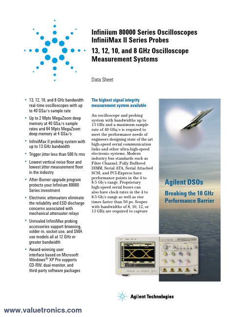
Infiniium 80000 Series OscilloscopesInfiniiMax II Series Probes13, 12, 10, and 8 GHz OscilloscopeMeasurement SystemsData Sheet•13, 12, 10, and 8GHz bandwidthreal-time oscilloscopes with upto 40GSa/s sample rate•Up to 2Mpts MegaZoom deepmemory at 40GSa/s samplerates and 64Mpts MegaZoomdeep memory at 4GSa/s•InfiniiMax II probing system withup to 13GHz bandwidth•Trigger jitter less than 500fs rms•Lowest vertical noise floor andlowest jitter measurement floorin the industry•After-Burner upgrade program protects your Infiniium 80000Series investment •Electronic attenuators eliminate the reliability and ESD discharge concerns associated withmechanical attenuator relays •Unrivaled InfiniiMax probing accessories support browsing,solder-in, socket use, and SMAuse models all at 12GHz orgreater bandwidth•Award-winning userinterface based on MicrosoftWindows®XP Pro supportsCD-RW, dual-monitor, andthird-party software packagesAgilent DSOsBreaking the 10 GHzPerformance Barrier The highest signal integritymeasurement system availableAn oscilloscope and probingsystem with bandwidths up to13GHz and a maximum samplerate of 40GSa/s is required tomeet the performance needs ofengineers designing state of the arthigh-speed serial communicationlinks and other ultra-high-speedelectronic systems. Modernindustry bus standards such asFibre Channel, Fully BufferedDIMM, Serial ATA, Serial AttachedSCSI, and PCI-Express haveperformance points in the 4 to8.5Gb/s range. Proprietaryhigh-speed serial buses canalso have clock rates in the 4 to8.5Gb/s range as well as risetimes faster than 50ps. Scopeswith bandwidths of 8, 10, 12, or13GHz are required to capture2Benefitsthe frequency harmonics of such high-speed signals and make accurate and repeatable measurements on them.Agilent’s award-winning InfiniiMax probing system set the standard for probing systems and the rest of the oscilloscope industry is now following this trend-setting architecture. Agilent’s InfiniiMax II probing system takes thisinnovation to an unmatched level of performance and usability.U.S. Navy imagery used in illustration without endorsement expressed or implied.3/find/infiniimaxII45/find/infiniimaxIIKey trends in theelectronics market•Technologies with dramatically increased clock speeds and edge rates have emerged.•Very fast serial differential buses are being used to save board space, reduce power and provide better noise immunity.•Densely packed circuit boards,often with stacked daughter boards, increase the need to probe in very hard-to-reach places.Key benefits of the 80000 and InfiniiMax II Series•Up to 13GHz bandwidth can track even the fastest signal speeds.• A sample rate of up to 40GSa/s can measure high-speed differential buses reliably and repeatedly.•The innovative InfiniiMax II probing system supports even the most demanding mechanical access requirements without sacrificing performance.6•The full real-time bandwidth of the oscilloscope is supported by up to a 40GSa/s sample rate.•This industry-leading sample rate produces more accurate and repeatable measurements,avoiding measurement error and signal aliasing due to under sampling, as shown above. This is especially important for high-quality jitter measurements.•The combination of up to13GHz bandwidth and 40GSa/s sample rate makes the 80000Series ideal for designs that include: PCI-Express II, Serial ATA II/III, 6Gbs SAS, 4.25 and 8.5Gbs Fibre Channel, 4.8Gbs Fully Buffered DIMM, or other high-speed electronic signals.The DSO 80000 Series Produces Accurate and Repeatable Measurements5 Gb/s real-time eye diagram with DSO81004A 8 Gb/s real-time eye diagram with DSO81204A7/find/infiniimaxIIE2690A Timing Interval and Jitter Analysis software The Agilent E2690A Advanced Time Interval and Jitter Analysis Software, licensed from Amherst Systems Associates (ASA); offers the most powerful and comprehensive set of tools for exploratory debug of jitter, and it is remarkably easy to use. The E2692A Basic Time Interval and Jitter Analysis Software offers the basic tools you need for jitter debug with the same precision you get with the advanced version. Both advanced and basic software versions provide complete jitterdecomposition into its components – including deterministic, random, and total jitter – as well as AutoMeasure to provide quick insight.Jitter Application Software PackagesE2681A EZJIT Jitter analysis softwareIncludes the following key measurements:cycle-to-cycle jitter, n-cycle jitter, period jitter,time interval error, setup and hold time,measurement histograms, measurement trending, and jitter frequency spectrum.N5400A EZJIT Plus Jitter analysis softwareQuickly separate random and deterministic jitter components and estimate total jitter at low BER for standards compliance. Automatic clock recovery and pattern detection, an easy-to-use setup wizard and graphical display views integrated into the Infiniium oscilloscope software further simplify navigation and RJ/DJ analysis.Infiniium: “It’s like someone who sits down and actually uses a scope designed this one.”Steve Montgomery, Director of Engineering, Linx TechnologiesUp to 40 GSa/s sample rate on two channelssignificantly reduces the chances of aliasing,increases measurement accuracy, and delivers thefull real-time bandwidth of the oscilloscope on twochannels simultaneously.Four channels at 20GSa/s with 8GHz real-time bandwidth or full bandwidth equivalent time modes are also available.Get fast answers to your questions with the built-in information system. Infiniium’s task-oriented Setup Guide provides step-by-step instructions for several advanced measurements and procedures.See your signal more clearly with a large (8.4-inch) high-resolution color display. Infiniium’s bright TFT display with anti-glare coating lets you see the details of your signal from all angles.20 Gb hard drive, 3.5” 1.44 MB floppy drive and rear USB port make it easy to save setup files, data files, screen shots, etc.Identify anomalies easily with color-graded persistence, a colorful visual representation of waveform distribution.Label waveforms and add notes to your screen captures — Infiniium’s keyboard makes it easy.Drag and drop markers with your mouse or use the arrow keys.Easy access to advanced features like math functions and FFTs, is provided by the Windows-based graphical user interface. This GUI also gives you unique capabilities like drag-and-drop measurements and zooming, and offers a graphical equivalent to all front panel controls.Remote access with Web-enabled connectivity,e-mail on trigger, and GPIB over LAN allows you to access your scope from remote locations.64 Mpts acquisition memory at 4GSa/s sample rate on two channels allows you to capture long time windows at high resolution – such as identifying glitches due to a power supply start-up from reset.QuickMeas+ key gives you any five automated measurements with a push of a button. You can also configure this key to print/save screen shots, save waveforms, or load a favorite setup.8Zoom and search with instant response.Zoom into your signal using the horizontal scale knob and search through your waveform with the position knob. MegaZoom technology allows you to find your area of interest quickly and easily – even with 64 Mpts waveforms.Built-in CD-R drive on rear panel allows you to update the system software conveniently and can be used to install third-party application packages.9/find/infiniimaxIIHands-free operation with the Infiniium VoiceControl option. Just speak into the microphone to operate front-panel controls.Segmented memory acquisition mode captures bursting signals at maximum sample rate without consuming memory during periods of inactivity.Removable hard disk drive option is available for added data security.Install third-party software packages such as Excel, LabView, Agilent Vee, MATLAB®, anti-virus software, and more to perform customizedprocessing and automation of your oscilloscope or to make the scope compliant to the network environment of your company.An external monitor allows you to run third-party applications on a large, high-resolution display while using the scope’s built-in monitor for high-speed waveform display.Windows® XP Pro operating system.A familiar interface makes simple tasks simple.Infiniium’s analog-like front panel has a full set of controls color coded to the waveforms and measurements, making simple tasks simple.One-year standard warranty and a variety of Agilent support options protect your investment for the long term.10MHz reference clock can be input (optional) to or output (standard) from the scope to allow precise timebase synchronization with RF instruments or logic analyzers.A new 18 GHz, BNC-compatible connectorprovides a high signal fidelity connection to Agilent active probes, SMA adapters, and standard BNCs.AutoProbe interface completely configures your scope for use with the InfiniiMax probing system and previous generation Agilent active probes.10/100 Mbps LAN interface lets you easily print waveforms on networked printers, save your results on your office PC, share information with others,and control the scope over the Web.10Two new high-bandwidth InfiniiMax IISeries probe amplifiers have been added to the InfiniiMax product line. InfiniiMax I probe amplifiers and probe heads can also be used with DSO 80000 Series scopes for lower performance applications.InfiniiMax II: The World’s Best High-Speed Probing System Just Got Better12GHz Hi-BW solder-in differential probe head provides maximum bandwidth and minimizes capacitive loading to ≤210fF.Variable spacing from 0.2 to 3.3mm (8 to 130 mills).12GHz Hi-BW differential browser provides maximum bandwidth for hand-held or probe holder use. Variable spacing from 0.2 to 3.3mm (8 to 130 mills).InfiniiMax offers you the highest performance available for measuring differential andsingle-ended signals, with flexible connectivity solutions for today’s high-density ICs and circuit boards.InfiniiMax probes have fully characterized performance for all of their various probe heads.This includes:•Swept frequency response plot•Common mode rejection vs. frequency plot •Impedance vs. frequency plot •Time-domain probe loading plot •Time-domain probe tracking plotOne-year standard warranty on active probes and a variety of Agilent support options to choose from.Controlled impedance transmission lines in every probe head deliver full performance versus the performance limitations produced by traditional wire accessories.Probe interface software allows you to save the calibration information for up to 10 different probe heads per channel and will automatically retrieve calibration data for a probe amplifier as it is attached to the scope.High-input impedance active probes minimize loading, support differential measurements and DC offset, and can compensate for cable loss.Probe calibration software delivers the most accurate probe measurements, linear phaseresponse and allows various probe combinations to be deskewed to the same reference time.InfiniiMax II probe headsThe 54006A 7.5 GHz resistive divider probe is available as a low-cost probing alternative for casual inspection of signals.A flat frequency response over the entire probe bandwidth eliminates the distortion and frequency-dependent loading effects that are present in probes that have an in-band resonance.InfiniMax I probe headsProbe Performance Plots AvailableThe InfiniiMax II probe manuals contain an extensive set of performance plots (bandwidth, probe tracking, CMRR, step response, impedance) for various probe configurations. See the following web site for this information/manuals/scopes/01169-9700_man.pdfInfiniium 80000 Series Performance CharacteristicsInfiniiMax II Series Performance CharacteristicsOrdering InformationReturn to service center required U.S. List$10,000$17,000Ordering Information (continued)as power supplies, inverters, semiconductor measurements,500 MHz (with supplied 10073C passive probe)500 MHz (with 10073C passive probe and80000 Series oscilloscope)Take the frustration out of communications testing and prove your designs conform to industry standards with the E2625A Communications Mask Test Kit option. Infiniium’s familiar Windows interface makes it easy for you to access the masks you need and configure your tests.In addition, the E2625A Communication Mask Test Kit comes with a set of electrical communication adapters to ensure convenient, reliable and accurate connections to your device under test. Included are more than 20 industry standard ANSI T1.102 and ITU-T G.703 communication signal mask templates. Logic Analyzer/Oscilloscope Time-Correlation Fixture.E2699A N5391AThe Agilent Serial BERT generator N4901B (N4902B)option 200 provides high speed digital stimulus to yourdevice with PRBS or memory based pattern from150Mb/s up to 13.5Gb/s (7Gb/s). For mor information,see /find/pulse-generators.Product Web site Array For the most up-to-date andcomplete application and productinformation, please visit ourproduct Web site at:/find/infiniimaxII /find/infiniimaxIIAgilent Technologies’ Test and Measurement Support, Services, and AssistanceAgilent Technologies aims to maximize the value you receive, while minimizing your risk and problems. We strive to ensure that you get the test and measurement capabilities you paid for and obtain the support you need. Our extensive support resources and services can help you choose the right Agilent products for your applications and apply them successfully.Every instrument and system we sell has a global warranty. Two concepts underlie Agilent's overall support policy: "Our Promise" and "Your Advantage."Our PromiseOur Promise means your Agilent test and measurement equipment will meet its advertised performance and functionality. When you are choosing new equipment, we will help you with product information, including realistic performance specifications and practical recommendations from experienced test engineers. When you receive your new Agilent equipment, we can help verify that it works properly and help with initial product operation.Your AdvantageYour Advantage means that Agilent offers a wide range of additional expert test and measurement services, which you can purchase according to your unique technical and business needs. Solve problems efficiently and gain a competitive edge by contracting with us for calibration, extra-cost upgrades, out-of-warranty repairs, and on-site education and training, as well as design, system integration, project management, and other professional engineering services. Experienced Agilent engineers and technicians worldwide can help you maximize your productivity, optimize the return on investment of your Agilent instruments and systems, and obtain dependable measurement accuracy for the life of those products.For more information on Agilent Technologies’products, applications or services, please contact your local Agilent office. The complete list is available at:/find/contactus Phone or Fax United States:(tel) 800 829 4444(fax) 800 829 4433Canada:(tel) 877 894 4414(fax) 800 746 4866China:(tel) 800 810 0189(fax) 800 820 2816Europe:(tel) 31 20 547 2111Japan:(tel) (81) 426 56 7832(fax) (81) 426 56 7840Korea:(tel) (080) 769 0800(fax) (080) 769 0900Latin America:(tel) (305) 269 7500Taiwan:(tel) 0800 047 866(fax) 0800 286 331Other Asia Pacific Countries:(tel) (65) 6375 8100(fax) (65) 67556 0042Email:*****************Contacts revised: 05/05/05Product specifications and descriptions in this document subject to change without notice.© Agilent Technologies, Inc. 2005Printed in USA, May 12, 20055989-1487ENUS /find/emailupdates Get the latest information on the products and applications you select.Agilent T&M Software and ConnectivityAgilent's Test and Measurement software and connectivity products, solutions and developer network allows you to take time out of connecting your instruments to your computer with tools based on PC standards, so you can focus on your tasks, not on your connections. Visit /find/connectivityfor more /find/agilentdirectQuickly choose and use your test equipment solutions with confidence.Agilent Email UpdatesAgilent Direct。
CONTRONIX说明书

)仪表与2线制变送器电流信号的接线
A-S规格80×160尺寸的仪表(mm)
外形尺寸
开孔尺寸接线端子图
B-F规格96
外形尺寸
开孔尺寸接线端子图
开孔尺寸接线端子图
、
键调出当前参数的原设定值,闪烁位为修正位
通过键移动修改位,键增值、
键存入修改好的参数,自动转到下一参数。
键后将转到本组第
重复②
,直到显示
键进入修改状态,,,
密码在仪表上电时或
不松开,顺序进入各参数组,仪表显
键调出当前参数的原设定值,闪烁位为修改位
通过键移动修改位,键增值,
以符号形式表示参数值的参数,在修改时,闪烁位应处于末位。
重复④~ 以下为测量及显示相关参数,设置不正确,可能使仪表显示不正常。
、
种:
变送输出
变送输出有5个参数:
)——输出信号选择
补偿前温度+
影响,该温度可能会高于室温。
在实际应用中,补偿导线接到输入端子,仪。
Tektronix波形分析仪用户指南说明书

The TDS3000B Series of Digital Phosphor Oscilloscopes Provides Unmatched Performance and Portability at an Affordable PriceThe TDS3000B packs the power of Enhanced Troubleshooting• TDS3000B Series •/tds3000b2Digital Phosphor OscilloscopesTDS3012B •TDS3014B •TDS3032B •TDS3034B •TDS3052B •TDS3054Be*Scope ®Web-based Remote Controle*Scope means you can control your TDS3000B oscilloscope from anywhere,using the Internet and your PC.Simply battery pack,the TDS3000B Series oscillo-WaveAlert ™waveform anomaly detection alerts you to any waveform that deviates from the “normal”input.Easily document and analyze measurement results using OpenChoice ™software.Digital Phosphor OscilloscopesTDS3012B •TDS3014B •TDS3032B •TDS3034B •TDS3052B •TDS3054BDigital Phosphor Oscilloscopes • TDS3000B Series •3 Look for unintentional circuit noise with theTDS3000B Series’ FFT capability.TDS3000B Series Electrical Characteristics• TDS3000B Series •/tds3000b4Digital Phosphor OscilloscopesTDS3012B •TDS3014B •TDS3032B •TDS3034B •TDS3052B •TDS3054BTrigger SystemMain Trigger Modes – Auto (supports Roll Mode for 40ms/div and slower),Normal.B Trigger – Trigger after time or events.Custom video trigger allows the TDS3000B to trigger on standards such as RS343 (26.6 kHz scan rate).Trace and identify ITU-R BT.601 video signals with the TDS3SDI 601 serial digital video module.Digital Phosphor Oscilloscopes • TDS3000B Series •5Digital Phosphor OscilloscopesTDS3012B •TDS3014B •TDS3032B •TDS3034B •TDS3052B •TDS3054B• TDS3000B Series •/tds3000b6Digital Phosphor OscilloscopesTDS3012B •TDS3014B •TDS3032B •TDS3034B •TDS3052B •TDS3054BOrdering InformationTDS3012B, TDS3014B,TDS3032B, TDS3034B,TDS3052B, TDS3054B Standard AccessoriesProbes:2each P301010X passive probes (TDS3012B),4each P301010X passive probes (TDS3014B),2each P6139A 10X passive probes (TDS3032B and TDS3052B),4each P6139A 10X passive probes (TDS3034B and TDS3054B).Documentation:User manual (hard copy and CD),quick reference manual,programmer’s manual,and application module manuals.Power cord.Accessory tray.Protective front cover:Has holder for user manual and/or 3.5in.floppy disks.NIST-Traceable Certificate of Calibration.Please specify power plug and manual version when ordering.Recommended OptionOption BND –Available on all TDS3014B,TDS3034B and TDS3054B models.Includes TDS3GV communication module with OpenChoice ™software,TDS3AAM and TDS3LIM application modules,TDS3BATB battery pack and AC3000 soft carrying case.Recommended AccessoriesTDS3TMT –Telecom mask testing application module.TDS3AAM –Advanced analysis module.TDS3LIM –Limit test module.TDS3VID –Extended video application module.TDS3SDI –601 serial digital video module.TDS3GV –GPIB,VGA,RS-232interfaces,and TDSPCS1 OpenChoice ™PC Communication software.TDSPCS1 OpenChoice ™PC Communication Software –A collection of programs that enable fast and easy transfer communication between MS Windows PCs and Tektronix oscilloscopes.Available in single-license packages and included in TDS3GV communication module.Minimum System Requirements:500 MHz Pentium equivalent or greater 128 MBMS Windows 98 SE,XP Professional,Me or 2000MS Office 2000 or XP (for TDS toolbars only) – Excel 2000 or 2002; Word 2000or 2002Keyboard and mouse LAN,GPIB or serial connector WaveStar ™Software for Oscilloscopes –Microsoft Windows 98/Me/2000/NT 4.0Application.TDS3BATB –Lithium Ion battery pack for up to 3 hours continuous operation without line power.Note:The instrument must be grounded at all times.TDS3PRT –Plug-in printer adds easy,portable documentation capability to your TDS3000B or TDS3000 oscilloscope.Note:Printer operates on battery power only with TDS3000B Series oscilloscope.016-1907-00 –5-roll pack of paper for TDS3PRT plug-in thermal printer.TDS3CHG –Fast charger for battery pack.AC3000 –Soft case for carrying instrument.HCTDS32 –Hard plastic case for carrying instrument.RM3000 –Rackmount kit.Service Manual (TDS3000B Series) –English only (071-0972-00).TDS3GV Programmers Manual –English only (071-0381-01).TNGTDS01 –Self-paced self-study operator training kit.For customer training on this product outside the U.S.call 1-503-627-7510,inside the U.S.call 1-800-833-9200 ext.77510.Recommended ProbesADA400A –100X,10X,1X,0.1X high gain differential amplifier.P6243 –1 GHz,≤1 pF input C 10x active probe.P5205 –1.3 kV,100 MHz high voltage differential probe.P5210 –5.6 kV,50 MHz high voltage differential probe.P5100 –2.5 kV,100X high voltage passive probe.TCP202 –15 A,DC + peak AC 50 MHz AC/DC current probe.Digital Phosphor Oscilloscopes • TDS3000B Series •7Digital Phosphor OscilloscopesTDS3012B •TDS3014B •TDS3032B •TDS3034B •TDS3052B •TDS3054BServiceTektronix probes are expressly designed for your oscilloscope,with identical quality standards and built-in compatibility for optimum performance.Digital Phosphor OscilloscopesTDS3012B •TDS3014B •TDS3032B •TDS3034B •TDS3052B •TDS3054BOur most up-to-date product information is available at:Copyright © 2003,Tektronix,Inc.All rights reserved.Tektronix products are coveredby U.S.and foreign patents,issued and rmation in this public ationsupersedes that in all previously published material.Specification and price changeprivileges reserved.TEKTRONIX and TEK are registered trademarks of Tektronix,Inc.All other trade names referenced are the service marks,trademarks or regis-tered trademarks of their respective companies.09/03 HB/SFI3GW-12482-10 Digital Phosphor Oscilloscopes • TDS3000B Series •/tds3000b8Contact Tektronix:ASEAN / Australasia / Pakistan (65) 6356 3900Austria +43 2236 8092 262Belgium+32 (2) 715 89 70Brazil & South America55 (11) 3741-8360Canada1 (800) 661-5625Central Europe & Greece+43 2236 8092 301Denmark+45 44 850 700Finland+358 (9) 4783 400France & North Africa+33 (0) 1 69 86 80 34Germany +49 (221) 94 77 400Hong Kong(852) 2585-6688India(91) 80-2275577Italy+39 (02) 25086 1Japan81 (3) 3448-3010Mexico,Central America & Caribbean52 (55) 56666-333The Netherlands+31 (0) 23 569 5555Norway+47 22 07 07 00People’s Republic of China86 (10) 6235 1230Poland+48 (0) 22 521 53 40Republic of Korea82 (2) 528-5299Russia,CIS& The Baltics+358 (9) 4783 400South Africa+27 11 254 8360Spain +34 (91) 372 6055Sweden+46 8 477 6503/4Taiwan886 (2) 2722-9622United Kingdom & Eire+44 (0) 1344 392400USA1 (800) 426-2200USA(Export Sales) 1 (503) 627-1916For other areas contact Tektronix,Inc.at:1 (503) 627-7111Updated 20 September 2002 generator with the power of an arbitrary waveform generator,offering the performance needed to accuratelyexperience with 24-hour response to technical questionsonline support to request assistance,check service status or arrange for trainingturn-around service timereliable support with demonstrated on-time deliveryVisit /support。
Tektronix 80C00 光学采样模块数据手册说明书

80C00 Optical Modules for DSA8300 SamplingOscilloscope DatasheetThe Tektronix 80C00 optical sampling modules, when installed in DSA8300Digital Serial Analyzer sampling oscilloscopes 1, provide complete optical test solutions for telecom (125 Mb/s to 44.50 Gb/s) and datacom (gigabit Ethernet, 10 GbE, 40 GbE, 100 GbE, Fibre Channel to 16 GFC, and InfiniBand) applications, as well as general-purpose optical component testing. Other module features include an optical-to-electrical converter,average power monitor, one or more reference receiver filters, a full bandwidth optical path, optional integrated clock recovery 2, optional electrical clock recovery signal pickoff 3, and a universal optical input connector.Key performance specificationsOptical bandwidths to >80 GHzSingle and multi-mode, short and long wavelength optical signal supportOptical mask test solutions with sensitivities to -22 dBmOptical filters to support all common standard rates from 125 Mb/s to 44.5 Gb/sKey features10 Gb/s telecom and datacomHighly accurate ER calibrated (Extinction ratio) measurement option for increased repeatability and transferability of the measurement80C14 - Low-noise, high optical sensitivity, broad wavelength conformance testing for 10GbE, 40GbE (R4), 100GbE (X10) LAN,WAN, FEC, 10G Fibre Channel, 16G Fibre Channel (14.025 Gb/s),14G Infiniband FDR (14.06250 Gb/s)80C08D and 80C12B (w/ Option 10G or 10GP ) – low-noise, high optical sensitivity, and broad wavelength conformance testing for 10 GbE, 40 GbE (R4), 100 GbE (X10) LAN, WAN, FEC, 10G fibre channel, and 10 Gb/s telecom standards and FEC rates 80C11B 30 GHz optical bandwidth conformance testing and characterization for 10 gb/s telecom and datacom standards and FEC ratesClock Recovery solutions for 10 Gb/s applications80C14 clock recovery for rates ≥10 Gb/s is supported by CR175A (Sold separately)80C08D and 80C11B Integrated Clock Recovery supports All Current 10 Gb/s Standards or User-defined Rates from 9.8 Gb/s to 12.6 Gb/s (CR4)80C12B clock recovery for 10 Gb/s rate is supported by the 80A05 module or CR125A clock recovery instrument (Sold separately)1Also compatible with DSA8200, TDS/CSA8200, TDS/CSA8000B, and TDS/CSA8000 sampling oscilloscopes.280C07B, 80C08D, and 80C11B modules.380C10C (with opt. CRTP), 80C12B, and 80C14 modules.100 Gb/s and 40 Gb/s telecom and datacom80C10C 80 GHz optical bandwidth and lowest noise capability for performance testing and signal characterization of 40 gb/s NRZ,RZ, or optical duobinary data formats:80C10C Option F1 provides 70 GHz full bandwidth and fullyintegrated selectable reference receiver filtering, enablingconformance testing at either 1310 nm or 1550 nm for25.781 Gb/s (100GBASE-ER4 and 100GBASE-LR4),27.952 Gb/s (OTU-4), 39.813 Gb/s (OC-768/STM-256,VSR-2000 G.693, 40G NRZ G.959.1), 41.25 Gb/s (40GBASE-FR), and 43.018 Gb/s (OTU3, VSR-2000 w/ FEC, 4x10G LANPHY OTU3) in a single module80C10C Option F2 provides 55 GHz full bandwidth and fullyintegrated selectable reference receiver filtering, enablingconformance testing at either 1310 nm or 1550 nm for27.952 Gb/s (OTU-4) and 25.781 Gb/s (100GBASE-LR4 and100GBASE-ER4)80C10C Option F3 provides 80 GHz full bandwidth and fullyintegrated selectable reference receiver filtering, enablingconformance testing of 39.813 Gb/s (OC-768/STM-256,VSR-2000 G.693, 40G NRZ G.959.1), 41.25 Gb/s (40GBASE-FR), and 43.018 Gb/s (OTU3, VSR-2000 w/ FEC, 4x10G LANPHY OTU380C10C Clock Recovery for 25-44.5 Gb/s rates is supportedby the CR286A-HS or similar 4 (sold separately) and OptionCRTP (electrical signal outputs to 44.5 Gb/s)80C15 provides 32 GHz full bandwidth and fully integratedreference receiver filtering, enabling conformance testing of both single and multi-mode conformance testing at 850,1310 and1550 nm. The module includes bandwidth filters which support the following rates: 25.781 Gb/s (100GBASE-ER4, -LR4, -SR4,Inifiniband EDR); 27.952 Gb/s (OTU-4), and 28.05 Gb/s (32G Fibre Channel)Tributary telecom and datacom80C07B and 80C12B provide excellent optical sensitivity andbroad wavelength test capability80C07B, 80C12B multirate telecom conformance testing solutions from 125 Mb/s 5 (OC-3/STM-4) through 11.317 gb/s (10GFC w/FEC) and multirate datacom conformance testing solutions forFibre Channel, gigabit Ethernet, and Infiniband standards ApplicationsHigh-speed optical communications testingExtinction ratio and Q-factor measurementsEye-pattern and pulse shape analysisRelaxation oscillation testingOptical signal analysisCompliance testingNRZ, RZ, and optical duobinary signal characterization80C07B Multirate, datacom and telecomThe 80C07B module is a broad wavelength (700 to 1650 nm) optical sampling module optimized for testing multirate datacom telecom signals from 125 to 2500 Mb/s.With its amplified O/E converter design, this module provides excellent signal-to-noise performance, allowing users to examine low-power optical signals. The 80C07B can be optionally configured with clock recovery that supports 125, 155, 622, 1063, 1250, 2125, 2488, 2500, and 2666 Mb/s rates.80C08D Multirate, broad wavelength, high sensitivity 10 Gb/sThe 80C08D module is a broad wavelength (700 to 1650 nm) multirate optical sampling module providing datacom rate testing for 10GbE, 40GbE-R4, 100GbE-SR10 applications at 9.953, 10.3125, 11.0957 Gb/s and 10G Fibre Channel applications at 10.51875 Gb/s and 11.317 Gb/s. The80C08D also provides telecom rate testing at 9.953, 10.664, and10.709 Gb/s.With its amplified O/E converter design, this module provides excellent signal-to-noise performance and high optical sensitivity, allowing users to examine low power level optical signals. The 80C08D can be optionally configured with clock recovery options that can support any standard or user-defined rate in the continuous range from 9.8 to 12.6 Gb/s4Contact Tektronix for details.5125 Mb/s is supported by selecting 155 mb/s rate. Datasheet80C10C Multirate datacom and telecom25 Gb/s, 40 Gb/s, and 100 Gb/sThe 80C10C module provides integrated and selectable reference receiver filtering, enabling conformance testing at either 1310 nm or 1550 nm of all standard 25, 40 and 100 (4 x 25) Gb/s standard rates. The 80C10C has the following configurations:Option F1: Provides standard compliant optical reference receivers for the following rates (standards):25.781 Gb/s (100GBase-LR4 and 100GBase-ER4)27.952 Gb/s (OTU4)28.05 Gb/s (28G Infiniband EDR)39.813 Gb/s (OC-768/STM-256, VSR2000 G.693, 40G NRZ G.959.1)41.25 Gb/s (40GBase-FR)43.018 Gb/s (G.709 FEC, OTU3 4×10G LAN PHY)Option F2: Provides standard compliant optical reference receivers for the following rates (standards):25.781 Gb/s (100GBase-LR4 and 100GBase-ER4)28.05 Gb/s (28G Infiniband EDR)27.952 Gb/s (OTU4)Option F3: Provides standard compliant optical reference receivers for the following rates (standards):39.813 Gb/s (OC-768/STM-256, VSR2000 G.693, 40G NRZ G.959.1)41.25 Gb/s (40GBase-FR)43.018 Gb/s (G.709 FEC, OTU3 4×10G LAN PHY)In addition to the filter rates, the user may also select bandwidths for the 80C10C for optimal noise versus bandwidth performance for accurate signal characterization.When equipped with Option CRTP, an electrical signal pickoff is provided for clock recovery. Clock recovery, to 28.6 Gb/s, for the 80C10C is provided using the CR286A clock recovery instrument (sold separately).When equipped with Option HSPR, a separate high-sensitivity photo receiver is provided with independent electrical outputs that can be used with external equipment (such as a Tektronix BERTScope) for high accuracy optical measurements.The 80C10C is also optionally available in a bundled ordering configuration which includes a 70+ GHz electrical sampling channel.80C11B Multirate, 10 Gb/s datacom and telecomThe 80C11B module is a long wavelength (1100 to 1650 nm) multirate optical sampling module optimized for testing 10 Gb/s datacom and telecom standard rates at 9.953, 10.3125, 10.51875, 10.664, 10.709, 11.0957, 11.317, 12.50, and 14.025 Gb/s. With its high optical bandwidth of up to 30 GHz (typical) it is well suited for general-purpose high-performance 10 Gb/s optical component testing.The 80C11B can be optionally configured with clock recovery options that can support any standard or user-defined rate in the continuous range from 9.8 to 12.6 Gb/s.80C12B Multirate, broad wavelength, high sensitivity datacom and telecomThe 80C12B module is a broad wavelength (700 to 1650 nm) multirate optical sampling module providing telecom and datacom testing for standards from 155 Mb/s to 11.4 Gb/s. This highly flexible module can be configured to support a wide variety of 10 Gb/s applications, lower data rate applications (155 Mb/s to 7.4 Gb/s), or a combination of 10G and lower data rate standards.The low data rate applications include: Telecom applications from 155 to 2666 Mb/s, 1G, 2G, and 4G Fibre Channel, multilane standards such as 10GBASE-X4 and 4-Lane 10 Gb/s Fibre Channel, and Infiniband SDR and DDR rates.The supported 10 Gb/s application includes both datacom and telecom standards. The supported 10 Gb/s datacom applications include 10GbE, 40GbE-R4, 100GbE-SR10 applications at 9.953, 10.3125, 11.0957 Gb/s and 10G Fibre Channel applications at 10.51875 Gb/s and 11.317 Gb/s. The 80C12B also provides telecom rate testing at 9.953, 10.664, and 10.709 Gb/s.With its amplified O/E converter design, this module provides excellent signal-to-noise performance and high optical sensitivity, allowing users to examine low-power optical signals. Clock recovery for the 80C12B is provided using the 80A05 module or CR125A clock recovery instrument (sold separately).80C00 Optical Modules80C14 Multirate, high sensitivity, datacom and telecom 10 Gb/s and 14 Gb/sThe 80C14 module is a broad wavelength (700 to 1650 nm) multirate optical sampling module providing 8G, 10G, and 16G telecom and datacom testing. The supported 10 Gb/s datacom applications include: 10GbE,40GbE-R4, 100GbE-SR10 applications at 9.953, 10.3125, and 11.0957 Gb/ s. Fibre Channel applications include: 8.500, 10.51875, 11.317, and14.025 Gb/s. The 80C14 also provides telecom rate testing at 9.953,10.664, 10.709, and 12.5 Gb/s.With its amplified O/E converter design, this module provides excellent signal-to-noise performance and high optical sensitivity, allowing users to examine low power level optical signals. Clock recovery for the 80C14 is provided by the CR175A or CR286A (sold separately).80C15 Single/multi-mode multirate datacom and telecom 25 Gb/s and 100 Gb/sThe 80C15 module provides integrated and selectable reference receiver filtering, enabling conformance testing at either 850, 1310 nm or 1550 nm of all standard 25, and 100 (4 x 25) Gb/s standard rates. The 80C15 provides bandwidth filtering for the following rates:25.781 Gb/s (100GBase-SR4, 100GBase-LR4, 100GBase-ER4 andInfiniband EDR)27.952 Gb/s (OTU4)28.05 Gb/s (32G Fibre Channel)In addition to the filter rates, you can also select bandwidths for the 80C15 for optimal noise versus bandwidth performance for accurate signal characterization.Datasheet80C00 Optical Modules Module selectionSelection guide for 10Gb/s telecom and datacom applicationsSelection guide for 100Gb/s and 40 Gb/s telecom and datacom applications6When ordered with only F1-F12 filter options, the maximum optical bandwidth of the 80C12B is constrained by the highest bit-rate filter.7Modules with fiber inputs of 62.5 µm can accommodate 9 µm (single-mode) as well as 50 µm and 62.5 µm (multi-mode) fibers.8When ordered with clock recovery options, the mask test sensitivity of the 80C08D and 80C11 is reduced by 1 dBm.9The mask test sensitivity of the 80C12B is -22 dBm for filter rates < 1.250 Gb/s.10The RMS optical noise (both typical and maximum) for wavelengths other than 1550 nm is obtained by multiplying the values in the table above by the following factors: 1 × for 1310 nm, 2 × for 850 nm11Power meter accuracy = 5% of reading.12Modules with fiber inputs of 62.5 µm can accommodate 9 µm (single-mode) as well as 50 µm and 62.5 µm (multi-mode) fibers.DatasheetSelection guide for tributary telecom and datacom applications13When ordered with clock recovery trigger pick-off option (option CRTP), the mask test sensitivity of the 80C10C is reduced by 1 dBm.14The mask test sensitivity of the 80C15 is reduced by 3 dB (to -5 dBm) for 850 nm signals.15The RMS optical noise (both typical and maximum) for wavelengths other than 1550 nm is obtained by multiplying the values in the table above by the following factors— 80C10C: 1.3 for 1310 nm, 80C15:0.94 for 1310 nm and 1.4 for 850 nm16Power meter accuracy = 5% of reading.17When ordered with only F1-F12 filter options, the maximum optical bandwidth of the 80C12B is constrained by the highest bit-rate filter.18Modules with fiber inputs of 62.5 µm can accommodate 9 µm (single-mode) as well as 50 µm and 62.5 µm (multi-mode) fibers.19The mask test sensitivity of the 80C12B is -22 dBm for filter rates < 1.250 Gb/s.20The RMS optical noise (both typical and maximum) for wavelengths other than 1550 nm is obtained by multiplying the values in the table above by the following factors: 1 × for all calibrated wavelengths80C00 Optical ModulesSupported filter rates and clock recovery21Power meter accuracy = 5% of reading.22 2.488 and 2.500 Gb/s filters are standard with 80C7B. Select any two of the additional four filter rates when ordering (see Ordering information).23F0-F12You can configure 80C12B to support any 4 of the 12 < 10 Gb/s rates indicated (see Ordering information).24Use option 10GP to configure the 80C12 to support any 3 of the 12 <10 Gb/s rates indicated, as well as the 10-12 Gb/s rates (see Ordering information).25Draft version of 8.5 G Fibre Channel. New 8.5 GFC filter is identical to the 10GBase-R 10.31 Gb/s filter.DatasheetSpecificationsDimensions and weight22 2.488 and 2.500 Gb/s filters are standard with 80C7B. Select any two of the additional four filter rates when ordering (see Ordering information).23F0-F12You can configure 80C12B to support any 4 of the 12 < 10 Gb/s rates indicated (see Ordering information).24Use option 10GP to configure the 80C12 to support any 3 of the 12 <10 Gb/s rates indicated, as well as the 10-12 Gb/s rates (see Ordering information).80C00 Optical Modules Ordering information80C00 models80C07B Multirate datacom and telecom optical sampling module80C08D Multirate, broad wavelength, high sensitivity 10 Gb/s80C10C Multirate datacom and telecom 25 Gb/s, 40 Gb/s, and 100 Gb/s80C11B Multirate, 10 Gb/s datacom and telecom80C12B Multirate, broad wavelength, high sensitivity datacom and telecom80C14Multirate, high sensitivity datacom and telecom 10 Gb/s and 14 Gb/s80C155Single/multi-mode, multirate datacom and telecom 25 Gb/s and 100 Gb/sOptions80C07B2.488 Gb/s and 2.500 Gb/s filters are standard with the 80C07B. In addition, the user must select any one (1) of the following filter options:Opt. F1155, 622 Mb/sOpt. F2155, 1063 Mb/sOpt. F3155, 1250 Mb/sOpt. F4155, 2125 Mb/sOpt. F5622, 1063 Mb/sOpt. F6622, 1063 Mb/sOpt. F7622, 2125 Mb/sOpt. F81063, 1250 Mb/sOpt F91063, 2125 Mb/sOpt F101250, 2125 Mb/sOpt. CR1155, 622, 1063,1250, 2125, 2488, 2500, and 2666 Mb/s clock/data recovery80C08DOpt. CR19.953, 10.31 Gb/s clock recoveryOpt. CR210.31, 10.52 Gb/s clock recoveryOpt. CR4Continuous rate clock recovery supporting any standard or user-definable rate in the range from 9.8 to 12.6 Gb/sDatasheet80C10CThe 80C10C has three configurations (Option F1, F2, or F3). User must order one of these options with the module.Opt. F125.781, 27.952, 39.813, 41.25, 43.018 Gb/s filters, 70 GHz full bandwidthOpt. F225.781, 27.952 Gb/s filters, 55 GHz full bandwidthOpt. F339.813, 41.25, 43.018 Gb/s filters, 80 GHz full bandwidthOpt. HSPR Option HSPR (High Sensitivity Photo Receiver) provides a second, more sensitive single-mode optical input that supports typicalpower levels for the 40 Gb/s and 100 (4 x 25) Gb/s standards.The option also provides differential electrical outputs (50 Ω, AC coupled, differential 2.92 mm female connectors) on the modulefront panel, to 44.5 Gb/s, with a maximum 1 ps differential skew.A typical use for Option HSPR is to provide optical BER testing when using a Tektronix BERTScope.This option is compatible with options F1-F3, but is mutually exclusive from Opt. CRTPOpt. CRTP The option provides differential clock recovery trigger pick-off (CRTP) electrical outputs (50 Ω, AC coupled, differential 2.92 mmfemale connectors) on the module front panel, to 44.5 Gb/s, with a maximum 1 ps differential skew.This option is compatible with options F1-F3, but is mutually exclusive from Opt. HSPR80C10CE2Bundle Bundled ordering configuration includes 80C10C plus one 80E11X1 single-channel 70+ GHz electrical module (This bundle hasthe same ordering options as the 80C10C).80C11BOpt. CR19.953 Gb/s clock recoveryOpt. CR29.953, 10.66 Gb/s clock recoveryOpt. CR39.953, 10.71 Gb/s clock recoveryOpt. CR4Continuous rate clock recovery supporting any standard or user-definable rate in the range from 9.8 to 12.6 Gb/sOpt. 01 ER Calibrated (when ordered with new module); module will only work on mainframe with Windows XP or Windows 7 andoscilloscope FW V 5.0 and higher.ER Calibrated can be ordered as an upgrade to an existing module; order Opt. 01 + Opt. IFC (factory installation); factoryinstallation is required; module will only work on mainframe with Windows XP and oscilloscope FW V 5.0 and higher.80C12BThe 80C12B module provides user-selected filter options for measuring specified sets of standards. There are three module configurations available that must be specified when ordering:Option 10G provides Optical Reference Receiver (ORR) filters for all standard rates between 8.5 and 11.4 Gb/sOptions F0-F12 provide four "tributary" filters for standards at data rates from 155 Mb/s to 7.373 Gb/s. Select the four filter options when ordering the module.Option 10GP plus any three F1-F12 filters provides Optical Reference Receiver (ORR) filters for all standard rates between 8.5 and 11.3 Gb/s plus the three selected tributary standard rates.Opt. F0Unfiltered 12 GHz bandwidth and 8.5 Gb/s 26Opt. F1155.52 Mb/sOpt. F2622 Mb/sOpt. F3 1.0625 Gb/sOpt. F4 1.250 Gb/s26Option 10GP and F0 are mutually exclusive, as Option 10GP already includes Option F0.80C00 Optical ModulesOpt. F5 2.125 Gb/sOpt. F6 2.488, 2.500 Gb/sOpt. F7 2.666 Gb/sOpt. F8 3.125, 3.188 Gb/sOpt. F9 4.250 Gb/sOpt. F10 5.000 Gb/sOpt. F11 6.144 Gb/sOpt. F127.373 Gb/sOpt. 10G/10GP 268.500, 9.95, 10.31, 10.51, 10.66, 10.71, 11.1, 11.3 Gb/s, unfiltered 12 GHz bandwidthOpt. 01 ER Calibrated (when ordered with new module); module will only work on mainframes with Windows XP or Windows 7 andoscilloscope FW V 5.0 and higher. ER Calibrated can be ordered as an upgrade to an existing module; order Opt. 01 and Opt. IFC(factory installation)Service options (available for all 80C00 optical modules)Opt. C3Calibration Service 3 YearsOpt. C5Calibration Service 5 YearsOpt. D1Calibration Data ReportOpt. D3Calibration Data Report 3 Years (with Opt. C3)Opt. D5Calibration Data Report 5 Years (with Opt. C5)Opt. R3Repair Service 3 Years (including warranty)Opt. R5Repair Service 5 Years (including warranty)Recommended accessoriesInput connector adaptersWhile the FC/PC connector is standard with the 80C00 Series optical sampling modules, the input connector type can be interchanged with any of the following standard adapters:Biconic119-4515-xxD4/PC119-4514-xxDIAMOND 3.5 119-4558-xxDIN/PC 47256 119-4546-xxFC/PC119-5115-xxHP/PC119-4556-xxSC/PC119-5116-xxSMA119-4557-xxSMA 2.5 119-4517-xxST/PC119-4513-xx 11Tektronix is registered to ISO 9001 and ISO 14001 by SRI Quality System Registrar.DatasheetASEAN / Australasia (65) 6356 3900 Austria 00800 2255 4835*Balkans, Israel, South Africa and other ISE Countries +41 52 675 3777 Belgium 00800 2255 4835*Brazil +55 (11) 3759 7627 Canada180****9200Central East Europe and the Baltics +41 52 675 3777 Central Europe & Greece +41 52 675 3777 Denmark +45 80 88 1401Finland +41 52 675 3777 France 00800 2255 4835*Germany 00800 2255 4835*Hong Kong 400 820 5835 India 000 800 650 1835 Italy 00800 2255 4835*Japan 81 (3) 6714 3010 Luxembourg +41 52 675 3777 Mexico, Central/South America & Caribbean 52 (55) 56 04 50 90Middle East, Asia, and North Africa +41 52 675 3777 The Netherlands 00800 2255 4835*Norway 800 16098People's Republic of China 400 820 5835 Poland +41 52 675 3777 Portugal 80 08 12370Republic of Korea 001 800 8255 2835 Russia & CIS +7 (495) 6647564 South Africa +41 52 675 3777Spain 00800 2255 4835*Sweden 00800 2255 4835*Switzerland 00800 2255 4835*Taiwan 886 (2) 2722 9622 United Kingdom & Ireland 00800 2255 4835*USA180****9200* European toll-free number. If not accessible, call: +41 52 675 3777 Updated 10 April 2013 For Further Information. Tektronix maintains a comprehensive, constantly expanding collection of application notes, technical briefs and other resources to help engineers working on the cutting edge of technology. Please visit . Copyright © Tektronix, Inc. All rights reserved. Tektronix products are covered by U.S. and foreign patents, issued and pending. Information in this publication supersedes that in all previously published material. Specification andprice change privileges reserved. TEKTRONIX and TEK are registered trademarks of Tektronix, Inc. All other trade names referenced are the service marks, trademarks, or registered trademarks of their respective companies.09 Dec 201385W-15964-26。
TeKtronixTDS210数字示波器说明书
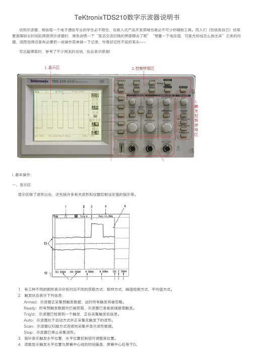
TeKtronixTDS210数字⽰波器说明书说到⽰波器,相信每⼀个电⼦通信专业的学⽣必不陌⽣,在嵌⼊式产品开发领域也是必不可少的辅助⼯具。
⽽⼈们(包括我⾃⼰)经常要是隔较长时间后再使⽤⽰波器时,难免会愣⼀下“直流交流切换的界⾯哪去了呢”“想量⼀下电压值,可是光标线怎么按出来”之类的问题,因⽽觉得还是有必要把⼀些操作简单做⼀下记录,毕竟好记性不如烂笔头~~~写这篇博客时,参考了不少⽹友的总结,在此表⽰感谢!I. 基本操作:⼀、显⽰区显⽰区除了波形以处,还包括许多有关波形和仪器控制设定值的指⽰等。
1.有三种不同的图形表⽰分别对应不同的获取⽅式:取样⽅式,峰值检测⽅式,平均值⽅式。
2.触发状态表⽰下列信息:Armed:⽰波器正采集预触发数据,此时所有触发将被忽略。
Ready:所有预触发数据均已被获取,⽰波器已准备就绪接受触发。
Trig'd::⽰波器已检测到⼀个触发,正在采集触发后信息。
Auto:⽰波器处于⾃动⽅式并正采集⽆触发下的波形。
Scan:⽰波器以扫描⽅式连续地采集并显⽰波形数据。
Stop:⽰波器已停⽌采集波形。
5.指针表⽰触发电平。
6.读数表⽰触发电平的数值。
7.图标表⽰的所选触发类型。
有如下⼏种:上升沿触发;下降沿触发;⾏同步视频触发;场同步视频触发。
8.读数表⽰视窗时基设定值。
9.读数表⽰主时基设定值。
10.读数显⽰了主时基的设定值。
11.读数显⽰了通道的垂直标尺系数。
12.显⽰区短暂地显⽰在线信息。
13.在屏幕上指针表⽰所显⽰波形的接地基准点。
如果没有表明通道的指针,就说明该通道没有被显⽰。
此外依据波形的类型有三种不同的显⽰形式:⿊线、灰线和虚线。
⿊⾊实线波形表⽰显⽰的活动波形。
获取停⽌后,只要引起显⽰精确度不确定的控制值保持不变,波形将保持⿊⾊。
在获取停⽌以后,可以改变垂直和⽔平控制值。
⽽参考波形和使⽤显⽰持续时间功能的波形以灰⾊线条显⽰。
虚线波形表⽰波形显⽰精确度不确定。
产⽣虚线的原因是停⽌获取后改变控制设定值,但仪器⽆法相应改变显⽰波形与其相配。
- 1、下载文档前请自行甄别文档内容的完整性,平台不提供额外的编辑、内容补充、找答案等附加服务。
- 2、"仅部分预览"的文档,不可在线预览部分如存在完整性等问题,可反馈申请退款(可完整预览的文档不适用该条件!)。
- 3、如文档侵犯您的权益,请联系客服反馈,我们会尽快为您处理(人工客服工作时间:9:00-18:30)。
)仪表与2线制变送器电流信号的接线
A-S规格80×160尺寸的仪表(mm)
外形尺寸
开孔尺寸接线端子图
B-F规格96
外形尺寸
开孔尺寸接线端子图
开孔尺寸接线端子图
、
键调出当前参数的原设定值,闪烁位为修正位
通过键移动修改位,键增值、
键存入修改好的参数,自动转到下一参数。
键后将转到本组第
重复②
,直到显示
键进入修改状态,,,
密码在仪表上电时或
不松开,顺序进入各参数组,仪表显
键调出当前参数的原设定值,闪烁位为修改位
通过键移动修改位,键增值,
以符号形式表示参数值的参数,在修改时,闪烁位应处于末位。
重复④~ 以下为测量及显示相关参数,设置不正确,可能使仪表显示不正常。
、
种:
变送输出
变送输出有5个参数:
)——输出信号选择
补偿前温度+
影响,该温度可能会高于室温。
在实际应用中,补偿导线接到输入端子,仪。