“SD”调节阀使用说明书
调节阀使用说明书
7 参数表 定位器参数表:
显示
功能
数值范围
1 模拟信号值 设定值类型
0…10V 0…20mA 4…20mA
2 初始化
气 动 头 和 定 位 器 的 没有初始化
初始化
初始化完成
返回到工厂设定 3 默认状态
没有默认 默认
11 实际 X 值 X 的显示方向和实际 上升
的变化方向 值的输出
下降
epos 1435 使用说明书
- 调节外部的节流阀使运行速度 > 1 秒 - 通过内部 OPEN/CLOSE 节流阀,调节运行时间(如果必须的话)。
epos 1435 使用说明书
4
11
24:SETP DIRECTION=setup in reverse
4.2 工厂安装(定位器已安装在阀上)
“A:AUTO”(自动模式)
在面板上显示,表示已初始化
2 电线连接 (1) 连接传感器(如果还没有连接的话) (2) 将 0/4-20mA 或 0-10V 的模拟信号连接到正确的终端接线柱上.
epos 1435 使用说明书
2
11
(3) 接通 24V 直流电的电源.
图: 接线柱配置 ∗关上定位器上面的外壳并用螺丝旋紧。密封及电缆不允许被破坏。
3 定位器的显示元件Biblioteka epos 1435 使用说明书
3
11
a. 按下“←”键,直到“C:CONFIG”出现。
b. 按住“→”键保持 3 秒钟,直到面板的上面显示 出现,设定值可以通过“+”和“-”键来进行选择(0-20mA, 4-20mA 或 0-10V)。 在选择输入的设定值后,
c. 按下“→”键,你将看到
出现在面板的上面显示处。按下
SD说明书-中文

调节阀手册

调节阀手册第一章概述O.P.小洛维特在现代化工厂的自动控制中,调节阀起着十分重要的作用,这些工厂的生产取决于流动着的液体和气体的正确分配和控制。
这些控制无论是能量的交换、压力的降低或者是简单的容器加料,都需要靠某些最终控制元件去完成。
最终控制元件可以认为是自动控制的“体力”。
在调节器的低能量级和执行流动流体控制所需的高能级功能之间,最终控制元件完成了必要的功率放大作用。
调节阀是最终控制元件的最广泛使用的型式。
其他的最终控制元件包括计量泵、调节挡板和百叶窗式挡板(一种蝶阀的变型)、可变斜度的风扇叶片、电流调节装置以及不同于阀门的电动机定位装置。
尽管调节阀得到广泛的使用,调节系统中的其它单元大概都没有像它那样少的维护工作量。
在许多系统中,调节阀经受的工作条件如温度、压力、腐蚀和污染都要比其它部件更为严重,然而,当它控制工艺流体的流动时,它必须令人满意地运行及最少的维修量。
调节阀在管道中起可变阻力的作用。
它改变工艺流体的紊流度或者在层流情况下提供一个压力降,压力降是由改变阀门阻力或"摩擦"所引起的。
这一压力降低过程通常称为“节流”。
对于气体,它接近于等温绝热状态,偏差取决于气体的非理想程度(焦耳一汤姆逊效应)。
在液体的情况下,压力则为紊流或粘滞摩擦所消耗,这两种情况都把压力转化为热能,导致温度略为升高。
常见的控制回路包括三个主要部分,第一部分是敏感元件,它通常是一个变送器。
它是一个能够用来测量被调工艺参数的装置,这类参数如压力、液位或温度。
变送器的输出被送到调节仪表一一调节器,它确定并测量给定值或期望值与工艺参数的实际值之间的偏差,一个接一个地把校正信号送出给最终控制元件一一调节阀。
阀门改奕了流体的流量,使工艺参数达到了期望值。
在气动调节系统中,调节器输出的气动信号可以直接驱动弹簧-薄膜式执行机构或者活塞式执行机构,使阀门动作、在这种情况下,确定阀位所需的能量是由压缩空气提供的,压缩空气应当在室外的设备中加以干燥,以防止冻结,并应净化和过滤。
SDVBDV阀门原理与手动操作

SDVBDV阀门原理与手动操作SDV和BDV阀门是常见的工业阀门,分别是静态密封阀门和双向阀门的缩写。
下面将对这两种阀门的原理和手动操作进行详细介绍。
1.原理:静态密封阀门(SDV)是一种通过阀门内外的静止密封结构来实现阀门开闭和流体控制的装置。
其主要由阀体、阀座、阀瓣和密封结构组成。
当阀瓣紧贴阀座时,阀门处于闭合状态,阻止流体通过;当阀瓣离开阀座时,阀门处于打开状态,允许流体通过。
2.手动操作:(1)首先,确保工作场所安全,佩戴个人防护设备。
(2)检查SDV阀门的各个零部件是否齐全,是否存在损坏或松动。
(3)使用工具(如扳手)操作阀门手轮或手柄,将阀门逐渐打开或关闭。
操作时要保持力度适中,避免过度用力或猛力操作,以免损坏阀门。
(4)在操作过程中,要经常观察阀门的开度,确保阀门能够顺利打开或关闭,并注意阀门是否存在异常声音或泄漏现象。
(5)若发现阀门无法正常开启或关闭,或者有泄漏现象,请及时停止操作,并检查阀门是否受损或需要进行维修。
二、BDV阀门的原理与手动操作:1.原理:双向阀门(BDV)是一种用于控制流体流动方向的阀门,通常由阀体、阀座、阀瓣和密封结构组成。
其特点是可以实现正向流体和逆向流体的控制。
当阀瓣紧贴阀座时,阀门处于闭合状态,阻止流体通过;当阀瓣离开阀座后,流体可以双向流通。
2.手动操作:(1)在进行手动操作之前,需要确保工作环境安全,穿戴个人防护设备。
(2)检查BDV阀门的各个零部件是否齐全,是否存在损坏或松动。
(3)使用工具(如扳手)操作阀门手轮或手柄,将阀门逐渐打开或关闭。
操作时需适度用力,以免损坏阀门。
(4)在操作过程中,要随时观察阀门的开度,确保阀门能够顺利打开或关闭,并注意阀门是否有异常声音或泄漏现象。
(5)若发现阀门无法正常开启或关闭,或存在泄漏现象,应立即停止操作,并检查阀门是否受损或需要进行维修。
总结:SDV阀门和BDV阀门都是常见的工业阀门,分别用于静态密封和双向流动的控制。
电动调节阀使用说明
电动调节阀使用说明格,将面临新的挑战,尤其是在国际矿业巨头继续扩大垄断,谈判双方实力严重失衡的大环境下。
实际上,今年的铁矿石价格谈判时间未到,却早已引起国内外的关注了。
目前,我国铁矿石自给率约为45%至50%,另外一半需要进口,进口分为现货进口和长期协议进口两部分。
作为世界上最大的铁矿石进口国,我国在世界上的地位绝对是举足轻重的。
然而,近几年来,我国钢企参加了几次国际铁矿石价格谈判,但效果都不明显。
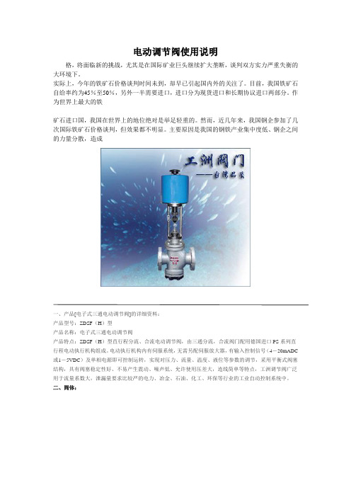
主要原因是我国的钢铁产业集中度低、钢企之间的力量分散,造成一、产品[电子式三通电动调节阀]的详细资料:产品型号:ZDSF(H)型产品名称:电子式三通电动调节阀产品特点:ZDSF(H)型直行程分流、合流电动调节阀,由三通分流,合流阀门配用德国进口PS系列直行程电动执行机构组成。
电动执行机构内有伺服系统,无需另配伺服放大器,有输入控制信号(4-20mADC 或1-5VDC)及单相电源即可控制运转,实现对压力、流量、温度、液位等参数的调节,采用平衡式阀塞结构,具有阀塞稳定性好、不易产生震动、噪声低、允许使用压差大,连线简单等特点,工洲调节阀广泛用于流量系数大,泄漏量要求比较严的电力、冶金、石油、化工、环保等行业的工业自动控制系统中。
二、阀体:形式:三通双座铸造阀公称通径:25-300mm公称压力:PM1.6 4.0 6.4MPa连接形式:法兰式按JB78-59 JB79-59材料:HT200 ZG230—450 ZG1Cr18Ni9TiZG0Cr18Ni12Mo2Ti三、上阀盖:常温型:-20℃-+200℃散热型:-40℃-+450℃压盖形式:螺栓压紧式填料:V型聚四氟乙烯填料、柔性石墨、不锈钢波纹管四、阀内组件:阀芯形式:双导向双座套筒型阀芯流量特性:等百分比特性,线性特性和快开特性材料:1Cr18Ni9Ti 0Cr18Ni12Mo2Ti五、执行机构:类型:可选PS、3810、ZAZ型(DN100以内)、DKZ型(DN100以上)系列电子式直行程执行机构。
Copes-vulcan调节阀使用维护手册

第二部分 维 护......................................................................................................... 9 2.1 注意事项......................................................................................................... 9 2.2 例行检查......................................................................................................... 9 2.3 从调节阀上拆卸执行机构.............................................................................. 11 2.4 解体调节阀 ................................................................................................... 11 2.5 装配调节阀 ................................................................................................... 14 2.6 装配执行机构................................................................................................ 19 2.7 研磨阀塞及套筒 ............................................................................................ 20
SDV15和XDV20液体液压阀门说明书

Instructions-Parts ListSDV15 and XDV20 Dispense Valve312789F- For non-metered dispensing of petroleum and synthetic-based oil - Models: Pages 2 and 31500 psi (10 MPa, 103.4 bar) Maximum Working PressureTI1466aSDV15 Model ShownENModelsModelsSDV15 Dispense Valve ModelsAll models include: 1/2 npt(f) swivel with locking-open triggerPart No.Extension Nozzles Fluid Type247712Rigid Automatic non-drip, quick close Oil247713Flexible Automatic non-drip, quick close Oil247714Gear Lube Automatic, non-drip, quick close Gear Lube247715Rigid Automatic, non-drip, quick close Anti-freeze247716Flexible Automatic, non-drip, quick close Anti-freeze247717NONE NONE AllAll models include: 1/2 - 14 BSPP swivel with locking-open triggerPart No.Extension Nozzles Fluid Type24H384Rigid Automatic non-drip, quick close Oil24H385Flexible Automatic non-drip, quick close Oil24H386Gear Lube Automatic, non-drip, quick close Gear Lube24H387Rigid Automatic, non-drip, quick close Anti-freeze24H388Flexible Automatic, non-drip, quick close Anti-freeze24H389NONE NONE AllAll models include: 1/2 - 14 BSPT swivel with locking-open triggerPart No.Extension Nozzles Fluid Type24H390Rigid Automatic non-drip, quick close Oil24H391Flexible Automatic non-drip, quick close Oil24H392Gear Lube Automatic, non-drip, quick close Gear Lube24H393Rigid Automatic, non-drip, quick close Anti-freeze24H394Flexible Automatic, non-drip, quick close Anti-freeze24H395NONE NONE All2312789FModelsXDV20 Non-metered Valve ModelsNPT Models - All models include locking-open and closed triggerPart No.Swivel Extension Nozzles Fluid Type 2477181/2” npt (f)Rigid High flow, non-drip, quick close Oil / Anti-freeze 2477211/2” npt (f)Flexible High flow, non-drip, quick-close Oil / Anti-freeze 2477223/4“ npt (f)Rigid High flow, non-drip, quck close Oil / Anti-freeze 2477233/4” npt (f)Flexible High flow, non-drip, quick close Oil / Anti-freeze 2477241/2” npt (f)NONE NONE Oil / Anti-freeze 2477253/4” npt (f)NONE NONE Oil / Anti-freezeBSPP Models - All models include locking-open and closed triggerPart No.Swivel Extension Nozzles Fluid Type 24H4071/2” - 14 BSPP Rigid High flow, non-drip, quick close Oil / Anti-freeze 24H4081/2” - 14 BSPP Flexible High flow, non-drip, quick-close Oil / Anti-freeze 24H4093/4“- 14 BSPP Rigid High flow, non-drip, quck close Oil / Anti-freeze 24H4103/4” - 14 BSPP Flexible High flow, non-drip, quick close Oil / Anti-freeze 24H4111/2” - 14 BSPP NONE NONE Oil / Anti-freeze 24H4123/4” - 14 BSPP NONE NONE Oil / Anti-freezeBSPT Models - All models include locking-open and closed triggerPart No.Swivel Extension Nozzles Fluid Type 24H4131/2” - 14 BSPT Rigid High flow, non-drip, quick close Oil / Anti-freeze 24H4141/2” - 14 BSPT Flexible High flow, non-drip, quick-close Oil / Anti-freeze 24H4153/4“ - 14 BSPT Rigid High flow, non-drip, quck close Oil / Anti-freeze 24H4163/4” - 14 BSPT Flexible High flow, non-drip, quick close Oil / Anti-freeze 24H4171/2”- 14 BSPT NONE NONE Oil / Anti-freeze 24H4183/4” - 14 BSPT NONE NONE Oil / Anti-freeze312789F3WarningsWarningsThe following warnings are for the setup, use, grounding, maintenance, and repair of this equipment. The exclama-tion point symbol alerts you to a general warning and the hazard symbol refers to procedure-specific risk. Refer back to these warnings. Additional, product-specific warnings may be found throughout the body of this manual where applicable.4312789FInstallation312789F 5InstallationGroundingThe equipment must be grounded. Grounding reduces the risk of static and electric shock by providing an escape wire for the electrical current due to static build up or in the event of a short circuit.Pump: follow manufacturer’s recommendations.Air and fluid hoses: use only grounded hoses. Air compressor: follow manufacturer’s recommenda-tions.Fluid supply container: follow local code.To maintain grounding continuity when flushing or reliev-ing pressure , always hold metal part of valve firmly to side of grounded metal pail, then trigger valve.Pressure Relief Procedure1.Turn off power supply to pump.2.Trigger valve into waste container to relieve pres-sure.3.Open any bleeder-type air valves and fluid drainvalves in the system.4.Leave drain valve open until you are ready to pres-surize the system.If you suspect the spray tip or hose is clogged or that pressure has not been fully relieved after following the steps above, VERY SLOWL Y loosen tip guard retaining nut or hose end coupling to relieve pressure gradually, then loosen completely. Clear hose or tip obstruction.Pre-Installation Procedure1.Relieve pressure as described in Pressure ReliefProcedure.2.Close fluid shut-off valve (A, F IG . 1).3.Ground hose, reel and console (See Grounding ).NOTICEDo not use PTFE tape on pipe joints; it may cause aloss of ground across the pipe joint.The equipment stays pressurized until pressure is manually relieved. To reduce the risk of serious injury from pressurized fluid, accidental spray from the dis-pense valve or splashing fluid, follow this Pressure Relief procedure whenever you:•Are instructed to relieve pressure•Check, clean or service any system component •Install or clean fluid nozzlesInstallation6312789FTypical InstallationF IG . 1 shows a typical installation. The installation is only a guide. The components shown are typical; however, it is not a complete system design. Contact your Graco distributor for assistance in designing a system to suit your particular needs.Dispense valves can also be installed on a console.Installation Procedure1.Relieve pressure , page 5.Steps 2 - 6 are the Flushing Procedure.2.Close fluid shut-off valve (A) at each dispense posi-tion.3.Make sure main fluid outlet valve at pump is closed,the air pressure to the pump motor is adjusted, and the air valve is open. Slowly open main fluid valve.4.Place hose end (with no dispense valve connected)into a container of waste oil. Secure hose in con-tainer so it will not come out during flushing. If you have multiple dispense positions, flush the dispense position farthest from pump first and work your way toward the pump.5.Slowly open fluid shut off valve (A) at dispense posi-tion. Flush out a sufficient amount of oil to ensure the entire system is clean. Close valve.6.Repeat Step 5 for all dispense positions.•Do not use this dispense valve on non-Graco con-soles. Such use could result in trigger becoming inadvertently pressed while valve is stowed.•To prevent line contamination, which can cause equipment damage or malfunction, flush the lines before your install the equipment in the system.F IGIf this is a new installation, or if the lines are contami-nated, flush the lines before you install dispensing valve.Key DescriptionA Fluid shutoff valveBHoseC Hose reel fluid inlet hoseD Hose reel EDispense valveA Thermal Relief Kit (not shown) is required.The Kit required will vary by pump selected. See Parts, page 16 for a list of available kits.Operation312789F 7Existing Installation1.Relieve pressure , page 5.2.Loosen and disconnect hose from old dispensevalve (the one you are replacing).Existing or New InstallationFor Steps 3 - 5 see F IG . 2.3.Thread extension (11) into outlet of the dispensevalve handle (1). Tighten securely.4.Apply thread sealant to male threads of hose fitting.Thread hose fitting into swivel (6). Tighten firmly.5.Thread nozzle (12) or nozzle adapter onto extensionand tighten firmly.6.Open all dispense position shut-off valves. Startpump to pressurize system.OperationFor part numbers referenced in these instructions, see Parts, page 10.Dispensing Procedure1.Open (or unlock) nozzle.2.Pull trigger (15) toward the valve handle (1) to openvalve and begin dispensing.3.Lock valve open by keeping trigger (15) squeezedand depressing trigger lock button (14). Then you can release trigger.4.To release trigger lock (14), pull trigger (15) towardvalve handle (1). 5.Release trigger (15) to stop dispensing.6.Close (lock) nozzle.•Do not overtighten extension.•Thread extension in at least three full turns. Position extension for proper alignment with valve handle (1) and tighten nut (11a).F IG. 2611a11121ti11466aTo reduce the risk of a serious bodily injury, including fluid injection, never exceed the maximum working pressure of the valve you are using or of the lowest rated component in your system.The XDV20 dispense valve trigger automatically locks whenever you release the trigger and must be unlocked each time you begin a new dispense.Troubleshooting8312789FTroubleshootingRelieve pressure before you check or repair dispense valve. Be sure all other valves and controls and the pump are operating properly.*Some fluid seepage is possible in applications where thermal expansion of fluid is possible.ProblemCauseSolutionSlow or no fluid flowScreen is clogged 1.Relieve pressure.2.Clean or replace strainer (4a)and washer 4b. Order Filter Kit 256164.3.If the problem remains, contactyour Graco distributor for repair or replacement.Pump pressure is low Shutoff valve is not full openOil leaks from swivel Swivel is looseT orque the swivel (6) to 7-10 ft-lb (9-13 N.m).If the problem remains, contact your Graco distributor for repair or replacement.O-ring is worn or damagedReplace swivel (6). Torque swivel to 7-10 ft-lb (9-13 N.m).If the problem remains, contact your Graco distributor for repair or replacement.Oil drips from nozzle*Nozzle is damaged or obstructed Inspect nozzle for damage or obstructions. Replace if damaged.Valve leaksO-rings or valve seat are worn or damagedReplace seals (9) and/or valve seat (2).Service312789F 9ServiceValve Handle Repair1.Relieve pressure , page 5.2.If you are replacing the seals (9), the cam (8) or thepush rod (3), remove the swivel (6) and remove the internal pieces. You must remove the cam in order to get the push rod out of the valve end.3.Remove screws (7) and washers (10) and removetrigger (15). 4.Push cam (8) out of valve handle (1). 5.Replace seals (9) and/or cam (8).6.Replace any worn or broken parts.7.Reassembly internal parts. Refer to F IG . 3 for cor-rect installation order and orientation of parts.8.Lubricate the cam (8) and slide it into the valve han-dle (1), making sure the notch is oriented as shown in F IG . 3, with the large end of the push rod (3) rest-ing in the notch of the cam.9.Replace the screws (7) and seals (9). Torquescrews to 15 -25 in-lb (1.7 to 2.8 N•m).10.Replace swivel (6). Torque to 7-10 ft-lb (31 to 44N•m).Filter ReplacementOrder Filter Kit 256164.1.Relieve pressure, page 5.2.Unscrew hose fitting from swivel (6).3.Remove swivel (6) from valve handle (1).4.Remove strainer (4a) and washer (4b) from inside ofswivel (6).5.Replace washer (4b) and strainer (4a). Refer to F IG .4 to ensure correct orientation of filter in swivel.6.Thread hose fitting into swivel (6) and tighten.Torque swivel to 7-10 ft-lb (31- 44 N•m).The large end of the push rod (3) fits into a notch in the cam (8) which is part of the trigger assembly. It is important you know this before you remove orinstall parts.The push rod (3) must be inserted through the out-let end of the valve handle before cam (8) is installed.F IG . 36173891015ti12073a710F IG . 4ti12074a14b 4a6Parts10312789FPartsSDV15 Dispense ValvesFN Part No.DescriptionQty 115R709HANDLE, valve, standard duty 12191313SEAT , valve 13277673ROD, push14256164KIT, filter, includes 4a and 4b 14a STRAINER 104b WASHER, plain106238399SWIVEL, straight, NPT 124H382SWIVEL, straight, BSPP 124H383SWIVEL, straight, BSPT 17110637SCREW, machine, pan head 28191315CAM19113574SEAL, quad ring 210191552WASHER, flat 211*KIT, nozzle and extension, page 12112*113113924SPRING, compression 11415R526LOCK, trigger 115191320TRIGGER 116192106GUIDE, spring 118113493SPRING, compression 120†172479T AG, warning 12215K672ADAPTER, o-ring, model 247714125†290180T AG, caution 1*These parts are not included on model 247717† Not shownFN Part No.DescriptionQty ti11467b64b4a18271013111215161413910781112111222T orque to 7-10 ft. lbs (9-13 N•m)112T orque to 15 - 25 in. lbs (1.7- 2.8 N•m)22Parts312789F 11PartsXDV20 Non-metered ValvesFN Part No.Description Qty 115M660HANDLE, valve, medium duty 1215U704SEAT , valve 13277673ROD, push 14256164KIT, filter, includes 4a and 4b 14a STRAINER 104b WASHER, plain 106247344SWIVEL, straight, 1/2 NPT models 247718, 247721, 247724124H097SWIVEL, straight, 1/2 BSPT, mod-els 24H413, 24H414, 24H417124H098SWIVEL, straight, 1/2 BSPP , mod-els 24H407, 24H408, 24H411247345SWIVEL, straight, 3/4 NPT models 247722, 247723, 24772524H099SWIVEL, straight, 3/4 BSPT, mod-els 24H415, 24H416, 24H418124H100SWIVEL, straight, 3/4 BSPP , mod-els 24H409, 24H410, 24H4127110637SCREW, machine, pan head 28191315CAM 19113574SEAL, quad ring 210191552WASHER, flat211*KIT, nozzle and extension, page 12112*113114680PIN, dowel 11415R016LATCH, pin 11515M886TRIGGER 11615R015LATCH, arm 11715R014LATCH, spring 11815R013LATCH, lever 120113493SPRING, compression 122†172479T AG, warning 12415U700PLUNGER, trigger, lift 12515U701SPRING, secondary 126†290180T AG, caution 1* These parts are not included on models 247724 or 247725† Not shownFNPart No.Description Qty ti12076a664b4a20217103121111710989171613181415T orque to 7-10 ft. lbs (9-13 N•m)1Torque to 15- 25 in. lbs (1.7- 2.8 N•m)222112524Parts12312789FSDV15 Nozzle Extension KitsPart No.DescriptionFluid Type*illustration note255852*Automatic, non-drip quick close nozzle with rigid extension.Oil255853*Automatic, non-drip quick close nozzle with flexible extensionOil255854Non-drip, quick close nozzle with rigid exten-sionGear Lube*Used for dispensing 5gpm (22.7 lpm) or less.continuedti11826ti11827ti11825ti11827ti11831ti11830ti12078aParts312789F 13255855*Non-drip, quick close nozzle with rigid exten-sionAnti-freeze255856*Non-drip, quick close nozzle with flexible extensionAnti-freeze255857Non-drip, quick close, high-flow nozzle with rigid extension Oil and Anti-freeze255858Non-drip, quick close, high flow nozzle with flexible extension Oil and Anti-freeze*Used for dispensing 5gpm (22.7 lpm) or less.Part No.Description Fluid Type*illustration noteti11826ti11828ti11825ti11828ti11826ti11829ti11825ti11829Parts14312789FSDV15 Nozzle KitsPart No.DescriptionQtyFluid Type255459*Automatic, non-drip, quick-close nozzle Oil• BODY , nozzle 1• O-RING, packing 1• SPRING, compression 1• O-RING, packing 1• STEM, nozzle, valve 1• SEAT, valve1255460*Automatic, non-drip, quick-close nozzle Anti-freeze• BODY , nozzle1• SPRING, compression 1• O-RING, packing 1• STEM, nozzle, valve,1• O-RING, packing 1• SEAT, valve1255461Automatic, non-drip, high-flow nozzle Oil and Anti-freezea • STEM, nozzle, qty 1b • BODY , nozzle, qty 1c • O-RING, packing, qty1d • O-RING, packing, qty 1e • O-RING, packing, qty 1255470Non-drip, quick-close nozzle Gear Lube • Housing 1• Body, nozzle 1• O-RING, packing 1• O-RING, packing,1• Plug, Hollow, hex1*Used for dispensing 5gpm (22.7 lpm) or less.Parts312789F 15XDV20 Nozzle Extension KitsXDV20 Nozzle KitsPart No.DescriptionFluid Type*illustration note255921Non-drip quick close,high flow nozzle with rigid extension. Oil and Anti-freeze255859Non-drip quick close, high flow nozzle with flexible extension.Oil and Anti-freezeti12680ati12679aPart No.DescriptionQtyFluid Type255793Non-drip, quick close, high flow nozzle Oil and Anti-freeze• O-RING, packing 1• O-RING, packing 1• BODY , nozzle, high flow 1• O-RING, packing 1• STEM, nozzle, heavy duty1Technical Data16312789FThermal Relief KitsTechnical DataPart No.DescriptionPSI (bar) Rating 112353Diaphragm pump for fuel dispense, valve only 50 psi (3.4 bar)235998Mini Fire-Ball ™ 225, 3:1 600 psi (41 bar)237601Fire-Ball 425, 3:1600 psi (41 bar)237893Fire-Ball 300, 5:1 and Fire-Ball 425, 6:1 900 psi (62 bar)248296Fire-Ball 300, 5:1 and Fire-Ball 425, 6:1 (same as 237893 minus bung adapter and swivel. Includes 6-foot hose)900 psi (62 bar)238899Diaphragm pump 150 psi (10.4 bar)240429Fire-Ball 425, 10:11600 psi (110 bar)248324Fire-Ball 425, 10:1 (same as 240429 minus bung adapter and swivel. Includes 6-foot hose)1600 psi (110 bar)Maximum Flow RangeSDV1515 gpm (56.8 lpm)XDV2020 gpm (75 lpm)Maximum Working Pressure SDV15/XDV201500 psi (102 bar)SDV15/XDV20 Weight 0.4 lbs (0.18 kg)Inlet See pages 2 and 3 for models and configuration information OutletSDV153/4 - 16 straight thread o-ring boss XDV207/8 - 14 straight thread o-ring Operating temperature range -40°F to 180°F (-40°C to 82°C)Wetted partsAluminum, Stainless Steel, CS, Acetal, Nitrile Rubber, TPE Fluid compatibilityAntifreeze, gear lube, oilNotes Notes312789F17All written and visual data contained in this document reflects the latest product information available at the time of publication.Graco reserves the right to make changes at any time without notice.Original instructions. This manual contains English. MM 312789For patents see: /patentsGraco Headquarters: MinneapolisInternational Offices: Belgium, China, Japan, Korea GRACO INC. P.O. BOX 1441 MINNEAPOLIS, MN 55440-1441Copyright 2008, Graco Inc. is registered to I.S. EN ISO 90015/2008, Revised May 2016Graco 7-Year Meter and Valve WarrantyGraco warrants all equipment referenced in this document which is manufactured by Graco and bearing its name to be free from defects in material and workmanship on the date of sale to the original purchaser for use. With the exception of any special, extended, or limited warranty published by Graco, Graco will, for a period from the date of sale as defined in the table below, repair or replace equipment covered by this warranty and determined by Graco to be defective. This warranty applies only when the equipment is installed, operated and maintained in accordance with Graco’s written recommendations.This warranty does not cover, and Graco shall not be liable for general wear and tear, or any malfunction, damage or wear caused by faulty installation, misapplication, abrasion, corrosion, inadequate or improper maintenance, negligence, accident, tampering, or substitution ofnon-Graco component parts. Nor shall Graco be liable for malfunction, damage or wear caused by the incompatibility of Graco equipment with structures, accessories, equipment or materials not supplied by Graco, or the improper design, manufacture, installation, operation or maintenance of structures, accessories, equipment or materials not supplied by Graco.This warranty is conditioned upon the prepaid return of the equipment claimed to be defective to an authorized Graco distributor for verification of the claimed defect. If the claimed defect is verified, Graco will repair or replace free of charge any defective parts. The equipment will be returned to the original purchaser transportation prepaid. If inspection of the equipment does not disclose any defect in material or workmanship, repairs will be made at a reasonable charge, which charges may include the costs of parts, labor, and transportation.THIS WARRANTY IS EXCLUSIVE, AND IS IN LIEU OF ANY OTHER WARRANTIES, EXPRESS OR IMPLIED, INCLUDING BUT NOT LIMITED TO WARRANTY OF MERCHANTABILITY OR WARRANTY OF FITNESS FOR A PARTICULAR PURPOSE .Graco’s sole obligation and buyer’s sole remedy for any breach of warranty shall be as set forth above. The buyer agrees that no other remedy (including, but not limited to, incidental or consequential damages for lost profits, lost sales, injury to person or property, or any other incidental or consequential loss) shall be available. Any action for breach of warranty must be brought within one (1) year past the warranty period, or two (2) years for all other parts.GRACO MAKES NO WARRANTY, AND DISCLAIMS ALL IMPLIED WARRANTIES OF MERCHANTABILITY AND FITNESS FOR A PARTICULAR PURPOSE, IN CONNECTION WITH ACCESSORIES, EQUIPMENT, MATERIALS OR COMPONENTS SOLD BUT NOTMANUFACTURED BY GRACO . These items sold, but not manufactured by Graco (such as electric motors, switches, hose, etc.), are subject to the warranty, if any, of their manufacturer. Graco will provide purchaser with reasonable assistance in making any claim for breach of these warranties.In no event will Graco be liable for indirect, incidental, special or consequential damages resulting from Graco supplying equipment hereunder, or the furnishing, performance, or use of any products or other goods sold hereto, whether due to a breach of contract, breach of warranty, the negligence of Graco, or otherwise.Graco InformationTO PLACE AN ORDER, contact your Graco distributor or call to identify the nearest distributor.Phone: 612-623-6928 or Toll Free: 1-800-533-9655, Fax: 612-378-3590Graco 7-Year Meter and Valve Extended WarrantyComponentsWarranty PeriodStructural Components 7 years Electronics3 years Wear Parts - including but not limited to o-rings, seals and valves1 year。
SDDRA-7...-6...三路压力减震阀说明书

3-Way Pressure-Reducing Valve, ISO Size 03 Q max = 60 l/min, p max = 315 barSandwich design, with manual adjustment, direct actingSeries SDDRA-7…S With cartridge valve, type DDRA-7L…-10…S Interface to ISO 4401-03-02S Full-flow secondary pressure reliefS Function in the P or A lineS5 pressure ranges availableS With pressure-gauge portS Excellent stability over the whole pressureand flow rangeS External cartridge parts with zinc-nickel plating1DescriptionSeries SDDRA-7…-6… sandwich valves are high performance, manually adjusted 3-way pressure-reducing valveswith a size 03 interface to ISO 4401-03-02. The main components of the valves are a sandwich body (stack-mountingbody) and the screw-in cartridge (type DDRA-7L…-10…).The pressure-reducing cartridges are direct acting and designed on the sliding-spool principle. Two models are available, one with the function in P and the other with the function A and an integral bypass check valve. These valves reduce the pressure in the secondary side of P or A (for flowIN) respectively to the value set at the pressure adjustment.The 3-way pressure-reducing cartridges function as full-flow pressure-relief valves from port P → T or A → T respectively as soon as the reduced pressure rises above thevalve pressure setting. A pressure-gauge port M (G1/4”) isalso provided in the secondary circuit. These sandwich valves are used to reduce the system pressure in mobile andindustrial applications. All external parts of the cartridge arezinc-nickel plated according to DIN EN ISO 19 598 and arethus suitable for use in the harshest operating environments. The sandwich body is sealed at its manifold side (theconnections side) by means of O-rings fitted in counterbores.2Technical dataGeneral characteristics Description, value, unitDesignation3-way pressure-reducing valveDesign sandwich design, with manual adjustment, direct acting Mounting method 4 x ∅ 5.4 holes for M5 cap screwsSize size 03 interface to ISO 4401-03-02 / DIN 24 340 A6 Weight 2.5…2.9 kgMounting attitude unrestrictedAmbient temperature range-25 °C … +80 °CSurface corrosion protection withoutHydraulic characteristics Description, value, unitMaximum operating pressure315 barFlow range…60 l/minNominal pressure ranges…30 bar, …60 bar, …100 bar, …160 bar, …250 barFlow direction see symbolsDescription, value, unitHydraulic characteristics Hydraulic fluidHL and HLP mineral oil to DIN 51 524;for other fluids, please contact BUCHER Hydraulic fluid temperature range -25 °C … +80 °CViscosity range10…650 mm 2/s (cSt), recommended 15...250 mm 2/s (cSt)Minimum fluid cleanlinessCleanliness class to ISO 4406 : 1999class 20/18/153SymbolFunction in PP TB ASDDRA-7…-P-6…Function in A(for flow IN)P TB ASDDRA-7…-AZR-6…4Dimensions & sectional view4.1Function in P171 51)Valve side2)Connections side (manifold side)M Pressure-gauge port (with G 1/4” threaded plug, ED VSTI)4.2Function in A (for flow IN), with bypass check valve17s11)Valve side2)Connections side (manifold side)M Pressure-gauge port (with G 1/4” threaded plug, ED VSTI)5Installation informationIMPORTANT!When installing the valve, make sure that the mating face (the manifold interface) aligns with thevalve interface. Do not confuse the sandwich valve's manifold side and directional-valve side. Setthe required pressure with the adjusting screw(s1). After you have set the valve, lock the adjusting screw with the lock nut.ATTENTION!Only qualified personnel with mechanical skillsmay carry out any maintenance work. Generally,the only work that should ever be undertaken is tocheck, and possibly replace, the seals. Whenchanging seals, oil or grease the new seals thoroughly before fitting them.Seal kit NBR no. DS-401-N 3)Item Qty.Description14O-ring no. 012∅ 9,25 x 1,78 N9021Seal kit NBR no. DS-324-Nfor pressure-reducing cartridge DDRA-7L…IMPORTANT!3)Seal kit with FKM (Viton) seals, no. DS-401-V6Performance graphsIMPORTANT!Detailed performance data and other hydrauliccharacteristics can be found in the data sheet forthe 3-way pressure-reducing cartridge that is fitted (data sheet ref. no. 400-P-260701-E).7Ordering codeS =D =DR =A ... Q =Z ... R =7=L =P =AZR =6=25=16=10=06=03=S=(blank)=V =8Related data sheetsReference (Old no.)Description400-P-030501(i-31)Size 03 interface to ISO 4401-03-02400-P-2607013-way pressure-reducing valve, size 10, series DDRA-7L…-10…E 2021 by Bucher Hydraulics AG Frutigen, CH-3714 Frutigen****************************All rights reserved.Data is provided for the purpose of product description only, and must not be construed as warranted characteristics in the legal sense. The information does not relieve users from the duty of conducting their own evaluations and tests. Because the products are subject to continual improvement, we reserve the right to amend the product specifications contained in this catalogue.Classification: 430.305.305.330.315.355。
- 1、下载文档前请自行甄别文档内容的完整性,平台不提供额外的编辑、内容补充、找答案等附加服务。
- 2、"仅部分预览"的文档,不可在线预览部分如存在完整性等问题,可反馈申请退款(可完整预览的文档不适用该条件!)。
- 3、如文档侵犯您的权益,请联系客服反馈,我们会尽快为您处理(人工客服工作时间:9:00-18:30)。
COPES-VULCAN带快速更换内部部件的单座“SD”调节阀安装、运行、维护使用说明书SINGLE WEB “SD” TYPE CONTROL VALVE WITH QUICK CHANGE TRIM目录引言 (4)第一部分安装 (6)1.1 验收 (6)1.2 储存 (6)1.3 安装 (6)1.4 调试前复检 (9)1.5 执行机构及配件 (10)1.6 运行要求 (10)第二部分维护 (11)2.1 注意事项 (11)2.2 例行检查 (11)2.3 从调节阀上拆卸执行机构 (14)2.4 解体调节阀 (15)2.5 装配调节阀 (20)2.6 装配执行机构 (28)2.7 研磨阀塞及套筒 (31)图1 调节阀剖面图 (33)图2 螺栓紧固顺序 (36)表1 紧固力矩 (37)表2 阀塞和阀杆组件紧固力矩 (38)引言SD型调节阀是用于高温高压工况下的调节阀,其尺寸范围为3/4”、1”、1.5”、2”、3”、6”、8”、10”、12”、14”和16”(20mm、25 mm、40 mm、50 mm、80 mm、150 mm、200 mm、250 mm和300 mm、350 mm、400 mm),ANSI压力磅级由150磅级到2500磅级。
每个阀门由几个分项组件组成。
例如在图一中,阀体组件包含阀体〔1〕、阀盖螺栓〔13〕及阀盖螺母〔14〕和阀盖/阀体密封垫圈〔15〕。
阀盖组件包含阀盖〔2〕、盘根螺栓及螺母〔11〕和〔12〕,及根据阀门与执行机构的几种不同连接方式所需要配备的零件:压块连接包含压块〔22〕及内六角螺栓〔23〕;螺杆连接包含螺纹环〔32〕;螺栓连接包含螺栓〔33〕和螺母〔34〕。
盘根组件包含支撑环〔7〕、盘根〔8〕、盘根压盖或盖圈〔9〕及盘根紧固件〔10〕组成。
如果采用双盘根自然就包含两套盘根〔8〕及一个隔离套环〔24〕。
阀塞组件的构成取决于种类及尺寸,阀塞有平衡及非平衡式之分,尺寸有全尺寸及变径之分。
非平衡单座阀塞包含阀塞〔3〕、阀座〔5〕、套筒〔4〕、阀杆〔6〕、阀杆固定销〔17〕、和阀塞密封垫圈〔16〕。
平衡单阀座阀塞包含阀塞〔3〕、阀座〔5〕、套筒〔4〕、阀杆〔6〕、阀杆固定销〔17〕、和阀塞密封垫圈〔16〕及阀塞密封,也就是通常所称的”U”杯型密封圈〔18a〕其耐温范围为上限500°F(260℃),如果超过这个范围,那么只能采用两个活塞环密封〔19〕。
典型的阀杆锁定销是轴销,但是,在某些恶劣工况下应用的阀芯会使用实心销。
具体安装说明,见使用手册。
如果采用“U”杯型密封,那么必须同时配备定位环〔18b〕及定位持环〔18c〕。
阀座既可以是金属的也可以是非金属的,对于非金属阀座而言除了金属阀座〔5〕之外,还包含有一个嵌入金属阀座内的非金属阀座〔21〕。
变径阀塞也就是阀塞尺寸较阀体尺寸小,因此,这种阀塞需配备另外一个阀塞密封垫圈〔16〕及变径持环〔20〕。
SD系列调节阀可配置特殊的阀芯,对于这种配置DeZURIK Copes-Vulcan公司将提供相应的手册。
第一部分安装1.1 验收当收到阀门后应立即开箱检查阀门是否在运输过程中有损伤,同时对照每个阀门均配备的装箱单确认阀门及配件与装箱单是否相符。
1.2 储存假如阀门在安装之前需要储放一段时间。
我们建议将阀门进出口处的包装物取下,并在阀门内部均匀涂抹一层防尘涂料,然后将阀门进出口处重新密封好,阀门其余部位也应采取相应的防尘措施。
注意:所有防尘材料均应无害于阀门安装使用后所通过的液体工质。
1.3 安装阀门安装的正确与否将直接影响其能否长期稳定运行,阀门安装之前应将管道彻底清洗干净,因为在阀门开始启运时所发现的很多问题,都是由于管道内未清理干净的杂质所引起的。
定位在安装之前,应预先考虑阀门周边留有足够的空间做维修保养、解体阀门或执行机构。
对于较大尺寸的阀门,更应考虑留有足够的空间使用起吊设备。
阀门应安装在直管段上,并尽可能避开弯管或流体流速较高的管段,较理想的位置是阀门入口之上游10倍于管道直径的直管段,阀门出口之下游有5倍于管道直径的直管段。
尽可能将阀门垂直安装,如果受场地限制而必须水平或某一角度安装,那么必须谨慎考虑相应的支承问题,特别是那些配有较大执行机构的阀门。
如果阀门必须水平或某一角度安装,安装单位或用户必须事先通知DeZURIK Copes-Vulcan公司。
阀门本体进口处镶有“进口”标牌,请将此处对准阀门上游管道进行安装。
旁路为保证在阀门检修期间工艺流程的不间断,应考虑设置必要的旁路系统。
阀体连接方式根据系统的要求,阀门有螺纹、法兰、堆焊及对焊等几种连接方式,阀门计算选型表中有具体说明。
螺纹连接 - 管道上的螺纹必须洁净,无钝角,螺纹膏只能应用于外螺纹。
法兰连接 - 管道侧的法兰接口必须平直对准阀门安装,否则管道上的张力将使阀门变形并诱发运行故障。
焊接连接 - 管道接口必须平直对准阀门焊接,否则管道上的张力将使阀门变形并诱发运行故障。
应根据不同的阀体/管道材料采用适当的热处理方式及正规的焊接工艺。
至于是否要将阀塞拆除后才能进行焊接的问题,通常取决于安装公司的习惯做法,一般来说正确的焊接工艺过程不会对阀塞造成任何损伤,但对于有非金属阀座或配有“U”杯型密封的平衡式阀塞来说,如果此类阀塞结构在焊接过程中可能会遭受超过500°F或260℃以上的温度,那么就必须将阀塞拆除后再进行焊接,重新装配阀门时要使用新密封垫圈及密封。
如果要通过冲洗来清除调节阀内的铁渣和碎片,则应事先取出阀塞,避免受损。
如果决定焊接过程中不将阀塞取出,则在焊接和焊后热处理过程中使调节阀处于中间行程位置。
焊后热处理只能就地进行。
进行焊后热处理时,不要用热处理材料将阀体完全包住。
就地焊后热处理过程包括将管道/阀门上的一段加热到指定的温度范围。
焊缝两边的最小加热段宽度,管道表面最亮,应为焊接厚度或2”(51mm)中较小的一个。
为了不破坏热梯度,调节阀/管道上温度控制区向外的温度应逐渐减小。
应监视阀体腹板的温度为避免损坏元器件,该温度不应超过450°F(232℃)。
气源连接(气动执行机构)必须用黄铜或不锈钢管道及接头连接执行机构的气路,并在通气之前彻底清除及吹扫,以免有任何异物、油污及金属屑存在于气路管道内。
所有气动阀门均应配备空气过滤减压阀,各种气动设定参数均可在设计选型表中查到。
隔热保温层无论出于保温或安全起见,除了加长型阀盖部分之外都应在阀门正式调试之前对阀体及阀盖做足够的隔热保温处理。
如果在合同谈判期间对噪音控制有特殊规定,除了阀门本体要采用防噪音处理外,更要特别注意所有与阀门下游管道相联的支承、管道接头、或其它刚性连接都必须用隔音材料彻底包好,否则所有这些部位都可能会成为噪音来源。
1.4 调试前复检当阀门全部安装完毕之后,应进行最后一次复检。
1.4.1 流向确认 - 检查阀门入口处的标牌,并确认阀门安装装置是否正确。
1.4.2 检查气路 - 将通向执行机构的气路接通,确认各接头处无漏气现象。
1.4.3 行程确认 - 向执行机构输入不同的信号,确认阀门选种与选型表中的叙述是否一致。
1.4.4 控制的设定与阀门动作的一致性- 检查并确认所有控制元件(控制器/定位器)的联动与阀门/执行机构相应动作及阀门在气状态下的位置是否与设计一致。
1.4.5 弹簧预压缩力/无载荷全行程气压 - 确认这些数据与设定值相符。
注意:请参照相应的执行机构和定位器使用手册来了解如何调整执行机构弹簧预压缩力和定位器1.5 执行机构及配件由于阀门可采取多种不同类型的执行机构及各种配件,因此本手册不可能包罗万象,有关这些设备的说明及使用手册将在另外一套手册中叙述,另外,阀门选型表中可查出该阀门所配置的所有相关执行机构及配件。
1.6 运行要求从气泵站输出供给执行机构及控制器的压缩空气必须洁净与干燥,在输气管道上必须装有一定数量的过滤减压装置。
通常情况下,控制器的输入压力是20psi(1.4Bar),但针对不同的情况可参照制造厂家的说明书来获取正确的输入压力值,执行机构所需要的空气压力值可直接在选型表中查到。
对于其它种类的执行机构,例如电动、电液或液压等,可针对具体情况参照有关制造厂家的说明书/使用手册以及相应的电路/管道图作为安装指导。
第二部分维护2.1 注意事项在对调节阀的本体进行维护之前,重要的一点是将调节阀隔离并泄压。
另外,除了测试执行机构之外,必须将调节阀与气源和电气连接隔离或断开。
如果不遵循这些预防措施,可能造成人员伤亡。
进行诸如更换薄膜、填料或阀塞等维护时,可以不将调节阀从管道上取下。
拆卸执行机构非常简单,但是在进行任何工作之前最好将其移到车间。
与执行机构有关的特别说明或附件维护参见相应的说明书。
2.2 例行检查运行过程中调节阀的内部器件将会劳损和磨损。
因此,为了保持调节阀的最佳性能,建议定期对调节阀进行检查和维护。
检查的频率取决于现场的工作条件。
但是,大多数故障都发生在运行期间,建议在进行每年一次检查之前进行检查,直到得到满意的维护周期。
检查过程中,应检查阀体上的以下各项。
注意:进行内部检查之前,应确保有备用的填料、垫圈和密封环等。
如果发现内部部件有劳损,应有全套备件。
外部检查可能泄漏处2.2.1 泄漏点-盘根除了PTFE波浪式填料外,所有填料都可以通过紧固其上面的密封螺帽来调整填料密封圈。
如果使用PTFE波浪式填料并发生泄漏,不能用其它填料替换。
(参见2.4.1节和2.5.8节)对于螺栓压紧密封圈,如果调整填料螺帽不能消除,则更换填料。
如果填料密封圈又出现故障,则可能存在更严重的故障,请与DeZURIKCopes-Vulcan公司服务部门联系。
2.2.2 泄漏点 - 阀盖重新紧固阀盖螺帽,消除泄漏。
如果重新紧固阀盖螺帽不能消除泄漏,则更换阀盖垫圈(参见2.4.2节和2.5.7节)内部检查可能磨损及损坏处注意:进行内部检查之前,再次确认调节阀被隔离并与气源断开。
同时,应确保有备用的填料、垫圈和密封环等。
如果发现内部部件有劳损,应有全套的备件。
2.2.3 阀杆填料函表面的不平整将缩短填料的寿命。
阀杆的磨损表明存在振动,磨损的阀杆将与填料不匹配。
如果可能,则研磨阀杆消除泄漏,否则更换阀杆。
应将磨损的阀杆更换,并检查阀塞和套筒是否磨损过大(参见2.4.3节和2.5.6节)。
2.2.4 阀塞座面磨损将增加调节阀的泄漏量。
导向面磨损将导致振动过大或粘合。
如果损坏不能通过抛光去除,则将其更换(参见2.4.3节和2.5.6节)2.2.5 密封环单座平衡结构阀塞的阀塞不是装一个”U”杯密封圈就是装两个活塞环,在阀塞外表面和套筒镗孔之间起密封作用。
这个密封圈的损坏将影响阀塞平衡。
如果该密封圈损坏,则应将其更换(参见2.4.3节和2.5.6节)一个好的做法是每次拆开调节阀时都将密封环更换。