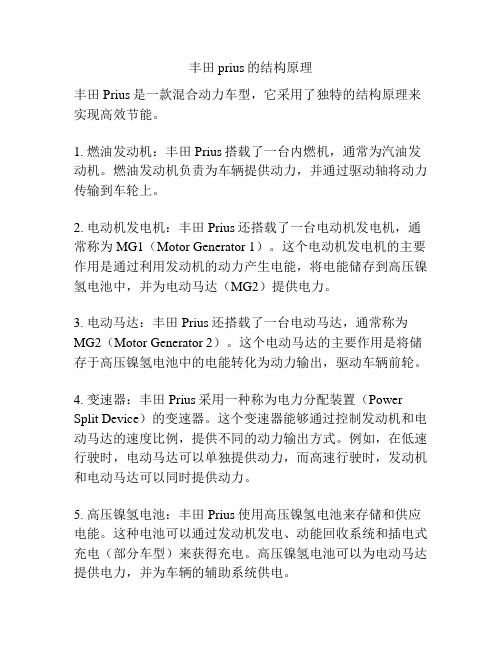
2004款Prius的电池系统
普锐斯混合动力电池主要控制技术分析

检修塞卡箍 蓄电池保险丝
1 号系统主继电器
互锁开关
带转换器的变频器总成
(-)
3 号系统主继电器
SMR2 闭合后的触点电流流向 继电器线圈电流流向
(b)SMR2 闭合后的电路(在 SMR1 和 SMR3 闭合前提下)
ECU
ECU
混 合 动 力 CON2 车 辆 控 制 CON1 CON3
(+) (-)
AUTOMOBILE MAINTENANCE
电压
蓄电池 ECU 总成
TB1 GB1
TB2 GB2
TB3
GB3
0
A
BC
D
蓄
E 时间
电 池
蓄 电 池
蓄 电 池
(+) SMR1 OFF
ON ON OFF
OFF
SMR2 OFF
OFF ON ON
OFF
温 度 传
温 度 传
温 度 传
(-) SMR3 OFF
ON ON ON
蓄电池 ECU 通过识别充/ 的目的。蓄电池温度检测电路如图
放 电 电 流 大 小 来 确 定 5 所 示 ,TB 端 子 为 信 号 电 压 端 ,GB
SOC 值。HV 蓄电池的温 端子为接地端,3 个温度传感器的检
HV 蓄电池总成 检修塞卡表 蓄电池保险丝 互锁开关
C-D 过程:从 C 点所对应时刻开 始 ,在 SMR1 和 SMR3 处 于 工 作 状 态 的基础上,SMR2 也处于工作状态,大 部分电流流经 SMR2,SMU 总成
混
合
动
力 车
CON2
辆
控
制
CON1
(+) 系统 2 号系统主继电器 主继 电器 1 号系统主继电器
Prius的工作原理

标题:Prius的工作原理浏览本帖图片prius先驱者(prius)好在哪里?主要是省油。
先看一下测试结果。
按照欧洲排放标准的测试方法,该车100公里耗油约4.4升,远远低于同级别(紧凑型中档轿车)其他非混合动力车。
也就是说100公里二氧化碳排放约102克,低于2012年生效的欧洲5标准的要求。
按照美国FTP测试方法,该车100公里耗油约3.7升,低于未来的SULEV(Super Ultra Low Emission Vehicle)标准。
它的工作原理是怎样的呢?大家都知道,混合动力的基本原理是:内燃机和电动机结合。
启动时电动机提供额外的扭矩,协助加速;刹车或下坡时,电动机能把部分动能反过来转换成电能,存储到电池中。
在启动停止频繁的市内交通里,这样就能节省能源。
而且,在电动机的支持下,内燃机可以尽可能多的以省油的模式以最优化的转速运行。
丰田混合动力技术基于这一原理,但是实现方式与众不同。
最大的特点:它有独立的发电机和电动机各一台;它的变速仅仅靠一套行星齿轮组,没有传统的机械变速箱和离合器(或是油压传动机构)。
其他的混合动力车,比如本田的Insight,只有一台电动-发电机,配上CVT或6速自动变速器。
这里要提及的是:丰田的电池是与松下电器联合研制和生产的,在Prius 里的重量仅仅是39千克。
丰田和松下下大功夫,大大减少了电池的记忆效应。
在美国市场,丰田为电池提供10年质保,在欧洲8年。
另外,发电机和电动机的工作电压均为500伏特,因而丰田专门开发了直流变压器,以便实现500V和14V的转换。
仅仅一套行星齿轮组,简直是不可思议。
怎么样就靠一组齿轮实现所有的档位包括倒车档?原理其实也很简单:发电机带动太阳轮(sun gear),内燃机带动行星轮(planet gear carrier),电动机与外环(ring gear)相连。
同时,电动机的输出轴直接与传动轴连接。
3台机器以不同的转速的和转向搭配就能实现任意输出速度和驱动模式。
丰田prius的结构原理
丰田prius的结构原理丰田Prius是一款混合动力车型,它采用了独特的结构原理来实现高效节能。
1. 燃油发动机:丰田Prius搭载了一台内燃机,通常为汽油发动机。
燃油发动机负责为车辆提供动力,并通过驱动轴将动力传输到车轮上。
2. 电动机发电机:丰田Prius还搭载了一台电动机发电机,通常称为MG1(Motor Generator 1)。
这个电动机发电机的主要作用是通过利用发动机的动力产生电能,将电能储存到高压镍氢电池中,并为电动马达(MG2)提供电力。
3. 电动马达:丰田Prius还搭载了一台电动马达,通常称为MG2(Motor Generator 2)。
这个电动马达的主要作用是将储存于高压镍氢电池中的电能转化为动力输出,驱动车辆前轮。
4. 变速器:丰田Prius采用一种称为电力分配装置(Power Split Device)的变速器。
这个变速器能够通过控制发动机和电动马达的速度比例,提供不同的动力输出方式。
例如,在低速行驶时,电动马达可以单独提供动力,而高速行驶时,发动机和电动马达可以同时提供动力。
5. 高压镍氢电池:丰田Prius使用高压镍氢电池来存储和供应电能。
这种电池可以通过发动机发电、动能回收系统和插电式充电(部分车型)来获得充电。
高压镍氢电池可以为电动马达提供电力,并为车辆的辅助系统供电。
6. 控制系统:丰田Prius采用一套复杂的控制系统来监测并协调燃油发动机、电动马达和高压镍氢电池之间的动力分配和能量流动。
这个控制系统能够根据行驶条件和驾驶需求实时调整不同部件的使用比例,以实现最佳的动力性能和燃油效率。
通过以上的结构原理,丰田Prius能够实现燃油发动机和电动机的协同工作,最大限度地提高能源利用效率,减少油耗和尾气排放。
这使得丰田Prius成为一款环保节能的汽车。
2004款Prius的评估
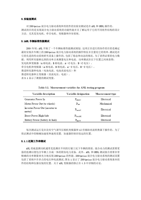
3.实验室测试对2004prius混合电力驱动系统和其组件的实验室测试是在ANL和ORNL操作的。
测试的目的是实现混合电力驱动系统的功能性能并且了解运用于它的不同组件结构的设计方法,尤其是发电机、牵引电机、变极器和冷却系统。
3.1ANL车辆标准性能测试2004年初,ANL开始了一个车辆标准性能测试规划。
这项正在进行的协作的目的是确定最初安装在车辆上的2004prius混合电力驱动系统的操作特征并且量化它的效率。
测试是在它的先进的传动系统研究设备上操作的,包括了稳态和动态的情况。
为了获得必要的电力数据,利用所有能够达到的功率点来测量电压和电流。
功率测试在以下位置之间来获得: 发电机和变极器(A相电流、B相电流、A—C电压、B—C电压),牵引电机和变极器(A相电流、B相电流、A—C电压、B—C电压),推进转化器和电池(电池电流、电池直流电压)和推进转化器和主变极器(直流电压、电流)。
表3.1显示了测量的测试变量。
每次测试运行是在没有空气调节压缩机变极器和12伏辅助直流转换器下操作的。
为了保证测试中的精确加速度和速度设置,加速器控制在较远的位置。
3.1.1近期工作和测试ANL的底盘测功机通常是监测在不同的行驶工况下车辆的排放。
混合动力的测试需要更强的监测以便包含车辆上合成一体的附加电力设备。
此外,ANL 和ORNL测试接合需要非常精确的功率测量来充分地实现2004prius的性能。
2004prius混合电力驱动系统的测试设置包括了系统中许多点的电压和电流测试。
图3.1显示了2004prius混合电力驱动系统基本组件的结构和仪器安装的位置。
关于ANL变极器的修正在4.3中详细的讨论。
图3.2显示了在测试中获得的数据随时间变化的一个实例。
它显示了车辆的速度在整个图表范围内,混合电力驱动系统不同部件的功率流。
观察曲线显示出,在车辆加速时发动机的功率较高,当车辆保持恒速时发动机功率降到零,因而允许电动机在没有发动机辅助下推动车辆。
Prius混合动力系统分析
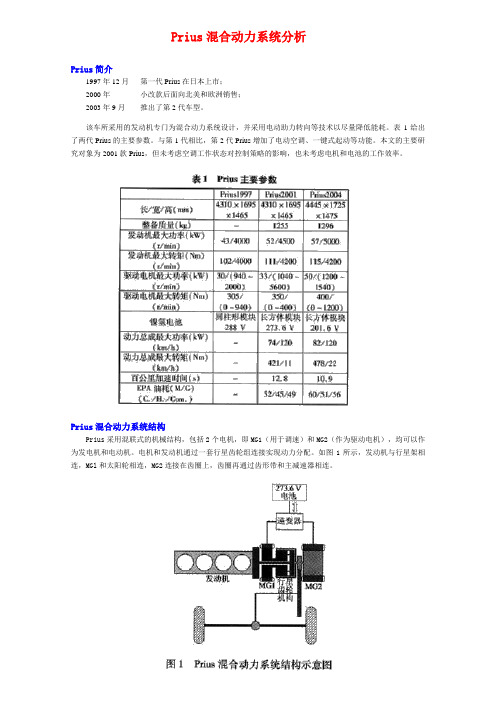
Prius混合动力系统分析Prius简介1997年12月第一代Prius在日本上市;2000年小改款后面向北美和欧洲销售;2003年9月推出了第2代车型。
该车所采用的发动机专门为混合动力系统设计,并采用电动助力转向等技术以尽量降低能耗。
表1给出了两代Prius的主要参数。
与第1代相比,第2代Prius增加了电动空调、一键式起动等功能。
本文的主要研究对象为2001款Prius,但未考虑空调工作状态对控制策略的影响,也未考虑电机和电池的工作效率。
Prius混合动力系统结构Prius采用混联式的机械结构,包括2个电机,即MG1(用于调速)和MG2(作为驱动电机),均可以作为发电机和电动机。
电机和发动机通过一套行星齿轮组连接实现动力分配。
如图1所示,发动机与行星架相连,MGl和太阳轮相连,MG2连接在齿圈上,齿圈再通过齿形带和主减速器相连。
电机和发动机之间具有以下的转速关系:n MG1+in MG2=(1+i)·n e(1)发动机输出的转矩一部分通过太阳轮作用在MGl上,一部分作用在齿圈上,且存在:其中:i=z ring/z sun说的具体点就是Prius混合动力汽车结构的核心部分是行星轮机构,丰田称之为动力分配装置(PSD,Power Split Device)。
结构示意图如下图:该行星轮系有两个自由度,在此结构中,发动机和行星架相联,通过行星齿轮将动力传递给外圈的齿圈和内圈的太阳轮,齿圈轴与电机和传动轴相联,太阳轮轴和发电机相联。
PSD将发动机大约70%的转矩直接传递到驱动轴上,将另一部分转矩传送到发电机上,并且发电机、电机和发动机的转速存在一线性关系。
在驱动轴转速(即电机转速)不变的情况下,通过调节发电机来调整发动机转速。
同时,发动机和电机转矩可以直接叠加。
但是结构上较为复杂,给制造和控制带来了一定的困难。
不同工况下混合动力系统工作状况1)发动机起动发动机起动分为热起动、冷起动。
热机状态下,MGl作为电动机拖动发动机达到1000 r/min以上后,发动机开始喷油,同时MGl进入发电模式,如图2所示,如果电池的充电需求为零,则发动机在运行约2 s后停机。
普锐斯混合动力汽车结构

1.5丰田普锐斯Prius工作性能
减速/能量回收时:
将减速时的能量回收到HV电池中用于再利用。
在踩制动踏板和松开油门时,普锐斯混合动力系统使 车轮的旋转力带动电动机运转,将其作为发电机使用。 减速时通常作为摩擦热散失掉的能量,在此被转换成电 能,回收到HV电池中进行再利用。
减速/能量回收时能量传递图
奥托循环 与 阿特金斯循环
2.进气返流减少了进入气缸中的燃料, 提高了燃油经济性。
奥托循环
进气返流
< 压缩行程105°
阿特金森循环
膨胀行程160°
阿特金森循环发动机配气
阿特金森循环原理
普锐斯配气相位(二代04款PRIUS 1NZ-FXE发动机)
气门正时
项目 进气
打开 关闭
排气
打开 关闭
排放标准
-A, -K
1.5丰田普锐斯Prius性能特点
传统车型
+
发动机
变速器
混合动力汽 车
发动机
电动机 传动桥
变频 转换器
HV蓄电池
怠速时
发动机运转->
消耗燃油
+
排放尾气
发动机停机-> 不消耗燃油
不排放尾气
怠速时
低负荷行驶
发动机 发动机运转->
运转->
消耗燃油
消耗
排放尾气
燃油
+ 排放 尾气
发动机 停机->
不消耗 燃油
2.0 mm (0.079 in.)
1.5 mm (0.059 in.)
其它 PVD涂层可提高抗磨损能力 使用钢铁材料提高抗磨损能力
-
2.3 丰田Prius 汽油机其它结构特点
丰田镍氢电池单片参数
丰田镍氢电池单片参数
丰田的镍氢电池单片参数因不同型号而异,以下是一些典型的丰田镍氢电池单片参数:
1. 丰田第一代Prius(1997-2003年)的镍氢电池单片容量约为6.5Ah,电压为1.2V。
2. 丰田第二代Prius(2004-2009年)的镍氢电池单片容量约为6.5Ah,电压为1.2V。
3. 丰田第三代Prius(2010-2015年)的镍氢电池单片容量约为6.5Ah,电压为1.2V。
4. 丰田第四代Prius(2016年至今)的镍氢电池单片容量约为6.5Ah,电压为1.2V。
需要注意的是,以上数据仅供参考,具体的参数可能会因车型、年份和其他因素而略有不同。
此外,镍氢电池相对于锂离子电池来说,能量密度较低,重量较大,但具有更好的安全性和环保性。
丰田普锐斯历程
丰田普锐斯发展历程丰田普锐斯简介∙ 目录∙ 丰田普锐斯简介 ∙ 开发∙ 1997–2001 (NHW10) ∙ 2001–2003 (NHW11) ∙ 2004–2009 (NHW20) ∙ 2009– (ZVW30) ∙车型对比丰田普锐斯(Toyota Prius )是日本汽车制造商丰田旗下的一款全混合动力电动中型车。
美国环保署(EPA )的数据显示,普锐斯是目前美国市场燃油效率最高的汽车。
EPA 和加州空气资源委员会(CARB )在烟雾和有毒废气排放标准的基础上都将普锐斯评为美国市场最清洁的汽车。
普锐斯于1997年开始在日本发售,是第一辆大规模量产的混合动力汽车。
2001年开始抢占世界市场,在全球超过40个国家和地区发售,其中最大的就是日本和美国市场。
2008年5月,普锐斯的全球累计销量达到里程碑式的100万辆,2010年初更是达到了160万辆。
其中美国市场就占据了一半的数据,截至2009年12月在美国共售出814,173辆。
开发1992年1月16日,丰田汽车公司发布了《地球宪章》,这是一个阐述丰田开发和销售低排放汽车的目标的文件。
1993年9月,丰田研发中心的执行副总裁Yoshirio Kimbara 成立了G21团队来研发新世纪的汽车。
1994年2月1日,G21计划小组第一次正式会议举行。
该团队决定G21的目标就是创造一辆既对资源和环境友好又保留了现代汽车精华的汽车。
开发工作由Takehisa Yaegashi 主持,负责制造一辆可以弥合电动车和汽油动力车之间的差距的汽车。
1995-1996(原型)1994年底,G21团队设计出一款混动动力概念车,并在次年的东京车展中将其推出。
该车被命名为“Prius 普锐斯”,在拉丁语中意为“prior (优先)"或里程(之前)"。
1996年底,这辆概念车开始了试驾历程。
丰田普锐斯制造商 丰田 出产年份 1997至今 级别 混动动力车 布局FF 布局1996 普锐斯原型第一辆普锐斯(NHW10)于1997年12月10日开始发售。
丰田普锐斯电机及驱动控制系统解析
丰田普锐斯电机及驱动控制系统解析作为全球最成功的环保车型,丰田普锐斯(PRIUS)早已成为油电混合动力车型中的全球销量冠军,即使在我们的身边,也经常可以见到它们的身影。
目前,在国内生产的丰田普锐斯(PRIUS)是采用丰田第二代混合动力系统,集发动机和电动机组合而成的并行混合动力车(图1)。
丰田第二代混合动力系统(THS-Ⅱ),可以根据车辆行驶状态,灵活地使用2种动力源,并且弥补2种动力源之间不足之处,从而降低燃油消耗,减少有害气体排放,发挥车辆的最大动力。
由于其THS-Ⅱ电机及驱动系统结构复杂,技术先进,本文将为大家详细介绍该系统的结构及基本原理,以帮助读者更进一步了解THS-Ⅱ系统。
一、THS-Ⅱ电机及驱动控制系统的特点1.在电动机和发电机之间采用AC500V高压电路传输,可以极大地降低动力传输中电能损耗,高效地传输动力。
2.采用大功率电机输出,提高电机的利用率。
当发动机工作效率低时,此系统可以将发动机停机,车辆依靠电机动力行驶。
3.极大地增加了减速和制动过程中的能量回收,提高能量的利用率。
二、THS-Ⅱ电机及驱动系统基本组成1.HV蓄电池:由168个单格镍氢电瓶(1.2V×6个电瓶×28个模块)组成,额定电压DC20 1.6V,安装在车辆后备厢内。
在车辆起步、加速和上坡时,HV蓄电池将电能提供给驱动电机。
2.混合动力变速驱动桥:混合动力变速驱动桥由发电机MG1、驱动电机MG2和行星齿轮组成(图2)。
3.变频器:由增压转换器、逆变整流器、直流转换器、空调变频器组成。
(1)增压转换器:将HV蓄电池DC201.6V电压增压到DC500V(反之从DC500V降压到DC201.6V)。
(2)逆变整流器:将DC500V转换成AC500V,给电动机MG2供电。
反之将AC500V 转换成DC500V,经降压后,给HV蓄电池充电。
(3)直流转换器:将HV蓄电池DC201.6V降为DC12V,为车身电器供电,同时为备用蓄电池充电。
由Prius了解混合电动汽车的构造
1.5L排量,并采用VVT-i (根据 发动机的状态控制进气凸轮轴, 从而在所有速度范围内提高扭矩 ) 技术,ETCS-i(智能电子节气门 系统 )
HV的发动机和普通汽车的发动机 一样,不过尺寸上由于对空间的 需求要小与普通汽车,要更显得 精致,可靠。
Page 7
HV各组成部分------电动发动机Ⅰ
Page 4
关于普锐斯
目前现行的混合动力系统模式 分为串联式、并联式和混联式,普锐斯搭载的混联式 混合动力系统,集合了各式混合动力系统的优势; ·发动机和发电机可根据行驶状况共同驱动或分开单独使用 ·停驶时自动停止发动机,减少能量浪费 ·更有效地控制发动机和电动机,加速反应快捷而顺畅 其结构左如左图,在advisor中其仿真模型如右图:
HV各组成部分------电池组
HV Battery
HV电池组包括由6块1.2V的镍氢 蓄电池 单元组成一个模块,不 同型号的普锐斯所包含的模块 数量也不同,具体参照左图。
Page 15
补充:电池组的组成
主要包括:电池单元,电池单元ECU,系统总继电器
Page 16
补充:关于SMR
SMR,总继电器, 即起到控制电路的 作用,例如:当充 电的时候SMR1与 SMR3接通, RESISTOR(电阻) 起到限流的作用以 保护电路,当充电 完毕后断开SMR1, 接通SMR2,使电流 流通。
Page 20
The end
谢谢 本次演示到此结束
Page 5
普锐斯总体结构
主要组成:1:内燃机(IC Engine) 2:电动发电机Ⅰ(Motor Generator) 3:电动发电机Ⅱ 4:行星齿轮组(Planetary Gear Set) 5:电流转换器(Inverter) 6:电池组(Battery) 7:控制单元(ECU)
- 1、下载文档前请自行甄别文档内容的完整性,平台不提供额外的编辑、内容补充、找答案等附加服务。
- 2、"仅部分预览"的文档,不可在线预览部分如存在完整性等问题,可反馈申请退款(可完整预览的文档不适用该条件!)。
- 3、如文档侵犯您的权益,请联系客服反馈,我们会尽快为您处理(人工客服工作时间:9:00-18:30)。
Development of a New Battery Systemfor Hybrid VehiclesShuuichi NagataHiroya UmeyamaYoshiaki KikuchiHaruyoshi YamashitaElectric & Hybrid Vehicle Engineering Div.TOYOTA MOTOR CORPORATION1,Toyota-cho,Toyota,Aichi 471-8572Phone / FAX: +81-565-23-6346/5744AbstractToyota Motor Corporation has developed the next generation Prius, which reflects our continuous environmental effort. For the new Prius, we have developed a new Ni-MH battery that plays an important role in the Toyota Hybrid System. With this new battery, we have realized further downsizing, weight and cost reduction as well as improvement of its usability, foreseeing a full-scale popularization of hybrid vehicles in the future. By improving the electrode and cell-to-cell connection structure, the internal resistance was lowered, and a higher output power from the battery module was achieved. This allowed us to reduce the number of battery modules without any effect on output performance. The volume and weight of the battery pack was reduced by approximately 15% and 25% respectively. With the new Prius, the input/output current has increased due to the downsizing of the battery. This results in increasing of heat generation in the battery. In order to cope with this issue, both battery configuration and battery cooling structure have been redesigned. This allowed us to enhance the cooling performance and reduce the temperature variation between modules. Furthermore, we improved the accuracy of the SOC estimation by optimizing the battery control system, so that we can cope with the expansion of the SOC range caused by the downsizing of the battery.Keywords: Battery, Hybrid, Battery Pack, Ni-MH1.IntroductionToyota Motor Corporation started marketing Prius, the world’s first production hybrid vehicle in December 1997 to help save resources and prevent global warming. This vehicle was introduced to North America and Europe in 2000:[1]. A total of over 110,000 units have sold as of March 2003, making Toyota a leader in hybrid technology throughout the world.We have been able to provide the new Prius with the world’s highest level of environmental performance and driving pleasure, true to its concept. We have realized a compact and lightweight battery system with improved usability and performance. This paper outlines the improvements the new battery system has achieved.2.Development of Battery ModuleFig. 1 shows the battery module for the new Prius:[2]. Fig. 2 shows the transition of the specific power and the specific energy. The prismatic battery module configuration of the new Prius follows that of its predecessor for superior heat releasing performance and ease of installation. The internal resistanceFig 1: New Prismatic Battery Module Fig 2: Specific Power and Specific Energy of Battery Module has been reduced by 30% from the previous model. This was achieved by reducing reactive resistance through the improvement of the electrode material, and structural improvements to the cell-to-cell connection also reduced resistance of the parts. As a result, we have realized the world’s top level of the specific power by improving it by 35%, as compared to the previous model. Table. 1 shows the specifications of the battery module. For the ’97 model Prius, we adopted a cylindrical battery module with 6 cylindrical Ni-MH battery cells connected in series. For the ’01 model,we adopted rectangular cells, six of which were connected in series into an integrated prismatic battery module. In addition, to improve output, we reduced the internal resistance of the battery by improving the structure of cell-to-cell connection. The new type battery provides the best output by reducing the internal resistance without changing the battery frame and capacity.Table 1: Battery Module Specifications3. Battery Pack ConstructionThe aforementioned improvements have enabled the new battery pack to have the same output as the previous model, but with less modules. Since the supply voltage is reduced because of the lesser number of battery modules, it poses a problem of lowering of motor and generator efficiencies. However, to improve this, the new Prius has adopted the variable-voltage system. If the number of battery modules is reduced, raising the battery voltage to a high level of 500 VDC can efficiently drive the motor and generator. We have thereby succeeded in reducing the total number of battery modules from 38 to 28,while retaining the battery pack output performance.Fig. 3 shows the construction of the battery pack. The new battery pack has 28 modules laid in a single row. The modules are held together with the end plates on both sides and the upper and the lower restraint rods. We have reduced the overall battery pack volume by 15% and the weight by 25% with the reduced number of modules and the adoption of plastic end plates and so forth.New PrismaticPrismatic Cylindrical Voltage 7.2V7.2V 7.2V Capacity 6.5Ah 6.5Ah 6.5Ah Weight 1040g 1050g1090g Dimension285mm(L)19.6mm(W)114mm(H)275mm(L)19.6mm(W)106mm(H)35mm(_)384mm(L)Fig 3: Battery Pack Construction4.Battery System4.1Battery Pack StructureFig. 4 shows the structure of the battery pack. Similar to the previous model, the new Prius has the following high-voltage components built directly into the battery pack from the viewpoint of the electrical safety:· System Main Relay (SMR)Independently installed 3 relays make effective use of the dead spaces in the vehicle.· Service PlugA built-in fuse to the Service Plug improves maintainability. Fig. 5 shows System Main Relays and Service Plug circuit.· Current SensorThe method of battery SOC estimation has been revised to promote cost reduction.· Battery ECUThe Battery ECU calculates the SOC on the basis of the battery current, voltage, and temperature. It also monitors abnormality of the battery system. These signals are transmitted to the vehicle control system.We have accomplished a sharp reduction of the size, weight, and cost by revising the internal circuits.Fig 5: Battery System CircuitFig 4: Battery Pack Structure Service PlugBattery ECU Battery ModulesSystem Main RelaysResistorRestraint RodsEnd Plates Lower CaseBattery Modules4.2Battery ControlCompared with the previous Prius, the battery voltage has been reduced because of the lesser number of the battery modules. Consequently, because of the increased current to the same level of power charge and discharge, the fluctuation range of the SOC increases as shown in Fig. 6. In addition, the holding energy of battery pack has been reduced from 1.8 kWh to 1.3 kWh or 70% of the previous model.To cope with the shortage of necessary battery energy for running the vehicle, we have optimized the method of SOC estimation. This has enabled us to expand the range of SOC usage, and retain the same level of energy for actual use as the previous model.Fig 6: Battery Input/Output and SOC during urban driving5.Cooling PerformanceConditioned cabin air is circulated to cool the battery pack . Because of the reduced number of battery modules, the input/output current has increased compared to the previous model; even when charging and discharging the same power. Reducing the internal resistance of battery modules, which suppresses the heat generation to the level of the previous model, has solved this problem. Fig. 7 shows the flow of the cooling air, and Fig. 8 the transition of the battery temperature during urban driving. We have been able to reduce the temperature variation between the modules as compared to the previous generation. This has been accomplished by battery module reduction, the optimization of inlet/outlet ducts, and modification to the pack structure.Fig.7: Flow of the Battery Cooling Air[ ’01 Model ][ ’04 Model ]Rear SeatBlowerBattery PackOutlet DuctsInlet DuctsFig 8: Battery Temperature during urban driving6.Cycle LifeWe have promoted longer cycle life by improving the separator, and optimizing battery cell design.Fig. 9 shows the relationship between the charge/discharge pattern on actual vehicle converted into the running distance and the rise in the internal resistance. While the battery on the new Prius has improved output performance, it retains the cycle life equivalent to, or greater than, the previous model.Fig 9: Cycle Life Charactaristics7.Conclusion(1) We have been able to reduce the size and weight of the battery pack by improving the batterymodule, pack, and overall system.(2) We have improved the method of battery SOC estimation. This allows us to expand the usable rangeof SOC. This enables us to use the same level of energy as the previous model, even with the reduced number of battery modules.(3) The reduction of battery modules, and the optimized battery cooling construction have reduced thetemperature variation among the battery modules.(4) The improved separator, and the optimized battery cell design have realized the cycle life equivalentto, or greater than, the previous model.However, further technological development to reduce size, weight and cost of the battery pack is needed for the propagation of hybrid vehicles.[ ’01 Model ][ ’04 Model ]012345060012001800240030003600time [sect e m p e r a t u r e [??]-30-20-10010203040506070POWER [kW]12345060012001800240030003600time [sect e m p e r a t u r e [??]-30-20-10010203040506070POWER [kW]8.References[1]Tomokazu Yamauchi, Shogo Yoneda, Yoshiaki Kikuchi, Yoshimi Shoji. Development of a New Battery Systemfor Hybrid Vehicles, EVS17, 2000.[2]Masato Ohnishi, K oujiro Ito, Shin-ichi Yuasa, Noriyuki Fujioka, Takashi Asahina, Shinji Hamada, ToyohikoEto, Development of Prismatic Type Nickel/Metal-Hydride Battery for HEV, AABC, 2003.9.AuthorsShuuichi NagataAssistant ManagerElectric & Hybrid Vehicle Engineering Div.Power Train Development GroupToyota Motor CorporationTel: +81-565-23-5159 Fax: +81-565-23-5759 E-mail: nagata@shuuichi.tec.toyota.co.jpHiroya UmeyamaAssistant ManagerElectric & Hybrid Vehicle Engineering Div.Power Train Development GroupToyota Motor CorporationYoshiaki KikuchiAssistant ManagerElectric & Hybrid Vehicle Engineering Div.Power Train Development GroupToyota Motor CorporationHaruyoshi YamashitaAssistant ManagerElectric & Hybrid Vehicle Engineering Div.Power Train Development GroupToyota Motor Corporation。