先进的超声导波无损检测技外文文献翻译、中英文翻译、外文翻译
超声导波管道无损检测技术及应用
超声导波管道无损检测技术及应用
超声导波管道无损检测技术是一种先进的检测方法,被广泛应用于工业领域。
该技术主要利用超声导波在管道中的传播特性,对管道内部的缺陷进行无损检测。
相比其他传统的检测方法,超声导波管道无损检测技术具有高精度、高效率、无需拆卸管道等优点。
该技术的应用范围涵盖了石油化工、电力、航空航天、建筑等多个领域。
在石油化工行业中,超声导波管道无损检测技术被广泛应用于石油管道、化工管道、天然气管道等的检测和维护。
在电力行业中,该技术可以用于检测输电线路、变电站设备等的缺陷。
在航空航天领域,该技术可以用于飞机燃油管道、液压管道等的无损检测。
在建筑领域,该技术可以用于检测楼宇内部管道的缺陷,确保建筑物的安全和稳定。
总之,超声导波管道无损检测技术在工业领域中具有重要的应用价值,可以提高管道的安全性和可靠性,降低维护成本,对于保障生产和人民生命安全有着不可替代的作用。
- 1 -。
一种无损检测方法_超声波探伤
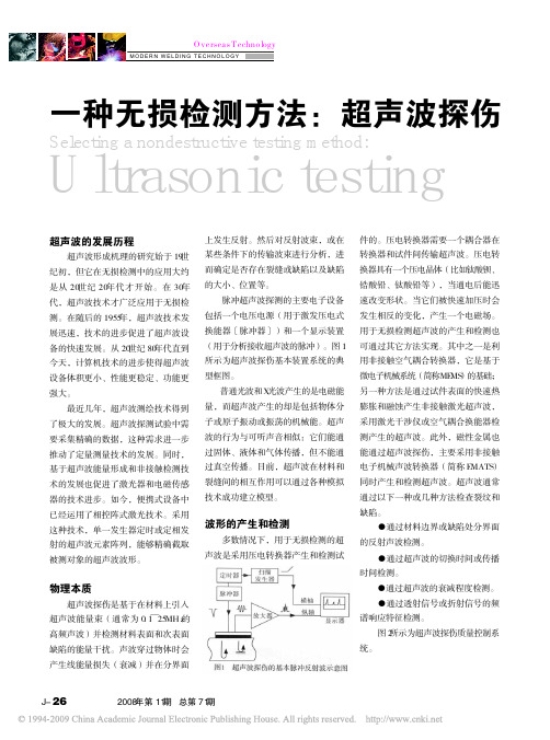
国外技术 Overseas TechnologyMODERN WELDING TECHNOLOGY一种无损检测方法:超声波探伤Selecting a nondestructive testing method:Ultrasonic testing超声波的发展历程超声波形成机理的研究始于19世 纪初,但它在无损检测中的应用大约 是从20世纪20年代才开始.在30年 代,超声波技术才广泛应用于无损检 测.在随后的1955年,超声波技术发 展迅速,技术的进步促进了超声波设 备的快速发展.从20世纪80年代直到 今天,计算机技术的进步使得超声波 设备体积更小,性能更稳定,功能更 强大. 最近几年,超声波测绘技术得到 了极大的发展.超声波探测试验中需 要采集精确的数据,这种需求进一步 推动了定量测量技术的发展.同时, 基于超声波能量形成和非接触检测技 术的发展也促进了激光器和电磁传感 器的技术进步.如今,便携式设备中 已经运用了相控阵式激光技术.采用 这种技术,单一发生器定时或定相发 射的超声波元素阵列,能够精确截取 被测对象的超声波波形. 上发生反射.然后对反射波束,或在 某些条件下的传输波束进行分析,进 而确定是否存在裂缝或缺陷以及缺陷 的大小,位置等. 脉冲超声波探测的主要电子设备 包括一个电压电源(用于激发压电式 换能器〔脉冲器〕)和一个显示装置 (用于分析接收超声波的脉冲).图1 所示为超声波探伤基本装置系统的典 型框图. 普通光波和X光波产生的是电磁能 量,而超声波产生的却是包括物体分 子或原子振动或振荡的机械能.超声 波的行为与可听声音相似:它们能通 过固体,液体和气体传播,但不能通 过真空传播.目前,超声波在材料和 裂缝间的相互作用可以通过各种模拟 技术成功建立模型. 件的.压电转换器需要一个耦合器在 转换器和试件间传输超声波.压电转 换器具有一个压电晶体(比如钛酸钡, 锆酸铅,钛酸铅等),当通电后能迅 速改变形状.当它们被快速加压时会 发生相反的变化,产生一个电磁场. 用于无损检测超声波的产生和检测也 可通过其它方法实现.其中之一是利 用非接触空气耦合转换器,它是基于 微电子机械系统(简称MEMS)的基础; 另一种方法是通过试件表面的快速热 膨胀和融蚀产生非接触激光超声波, 采用激光干涉仪或空气耦合换能器检 测产生的超声波.此外,磁性金属也 能通过超声波探伤,主要采用非接触 电子机械声波转换器(简称EMATS) 同时产生和检测超声波.超声波通常 通过以下一种或几种方法检查裂纹和 缺陷. ●通过材料边界或缺陷处分界面 的反射声波检测. ●通过超声波的切换时间或传播 时间检测. ●通过超声波的衰减程度检测. ●通过透射信号或折射信号的频 谱响应特征检测. 图2所示为超声波探伤质量控制系 统.波形的产生和检测多数情况下,用于无损检测的超 声波是采用压电转换器产生和检测试物理本质超声波探伤是基于在材料上引入 超声波能量束(通常为0.1~25MHz的 高频声波)并检测材料表面和次表面 缺陷的能量干扰.声波穿过物体时会 产生线能量损失(衰减)并在分界面J- 26 现代焊接 2008年第11期 总第71期Overseas Technology国外技术MODERN WELDING TECHNOLOGY表1超声波探伤的优点·穿透率高,在许多工件中穿透率大小可以达到几米,轴向能达到6米. ·敏感度高,可以检测极其微小的缺陷. ·检测工件内部缺陷的位置,估计缺陷大小,以及标识缺陷的取向,形状及其性质时准确度高. ·只需一个表面接触检测. ·电子化操作,几乎可以同时显示缺陷,适合于即时分析试验结果,自动化操作,快速扫描,在 线生产监测以及工艺控制. ·可从工件前表面至后表面进行整体扫描. ·无损害操作. ·便携. ·数字输出,可以利用计算机分析缺陷和材料性质.表2超声波探伤的缺点·人工操作需要工作人员具备专业技术并且小心仔细进行检测.超声波的类型超声波的类型很多,有纵波,横 波,表面波和平面波等.纵波传导时, 每个粒子都在平行于波动前进方向上 振动,呈现交替密集或稀疏的变化, 在超声波探伤中最常用.横波也在超 声波探伤中有广泛的应用,它的传播 有点类似于在绳子一端有规律地抖动 所形成的绳子的振动形式,分子和原 子在一个平面上垂直于波浪传播方向 上下振动;表面波只是有时才用在超 声波探伤中,它沿着平面或相对较厚 的曲面传播;平面波只是应用于超声 波探伤的某些场合,仅在厚度只有几 个波长大小的材料表面传播.界面处 超声波的反射与材料的物理状态关联 较大,而与材料本身的物理性能关联 较小.表1和表2列出了超声波探伤的 主要优缺点.·为制定出恰当的检测步骤需要多方面的技术知识. ·不能检测表面粗糙,形状不规则,体积太小或材质不均匀的工件. ·不能检测恰巧发生在紧邻工件表面下的薄层的缺陷. ·耦合介质通常需要在转换器和工件之间传输超声波能量. ·需要校准设备和标识缺陷的实际参考标准.被测物体. 2,以脉冲方式激发转换器,对准 被测物体并将超声波能量传入. 3,超声波能量在被测物体中传导, 反射和散射. 4,超声波能量在物体的内部的分 界面上继续传输或改变方向(检查被 测物体的几何特征或内部异常). 5,定位在或靠近被测物体的转换 器检测物体中传输或改变后的能量. 6,传导和反射的能量反应在时间 /频率图上,通过波形和波幅特征分析 和推测物体内部情况. 检测过程需要专用的设备和探针. 检测步骤,校准仪器和工艺控制都是 确保超声波在被测物体中的重复再现 所必需的.这种方法是一种表面和批操作者根据图形识别,信号大小,计 时和手动扫描定位等方法进行分析辨 别.但是因为手动扫描的变化不定, 显示器上输出值的变化也很大,手动 检测不能形成永久记录. 自动扫描时采用一个测量扫描仪 跟踪探针位置,并自动监测信号(时 间,相位,幅度等),形成一个能反 应被测物体内部结构的响应图.扫描 系统的分辨率在一定程度上取决于扫 描像素的保真度和检测信号的过滤和 处理情况.超声波扫描系统会自动生 成扫描图像和分析报告.人工和自动 扫描的相对特点在表3中进行了总结 和对比.结束语超声波探伤是一项成熟的技术, 它有坚实的物理学理论基础和成熟的表3 人工(手动)扫描检测与 自动扫描检测的比较人工 低 中 高 中 中 自动 中 高 中 高 低超声波探伤要求超声波探伤方法主要应用于检测 各种材料特性和状态.它适用于试样 表面缺陷和内部异常的检测.试样必 须能够传播超声波能量并具有引入和 检测反射,透射,散射声波能量的几 何结构.总的工艺步骤如下: 1,将超声波转换器固定或靠近于量检测工艺,根据工件某些特征的敏 感性和分辨率的高低不同,工艺步骤 也相应有所不同.手动和自动化技术随着超声波的应用发展,检测有 手动(人工)扫描和自动扫描之分. 人工扫描采用一台具有示波器的设备,检测成本 设备成本 操作者技术要求 工艺控制要求 工艺偏差要求现代焊接 2008年第11期 总第71期 J- 27国外技术 Overseas TechnologyMODERN WELDING TECHNOLOGY表4·裂纹 缺陷类型(超声 波探伤能检测的 缺陷类型) 缺陷大小 局限性 ·气孔 ·熔蚀超声波探伤总结实验室设备等,可满足用户不同的需 要.下列超声波电源和检测器可以根 据不同的检测要求进行选择:压电式 转换器,EMATS,激光器和激光干 涉仪,空气耦合转换器等.表4对超 声波探伤的各项性能进行了总结. 超声波无损探伤技术广泛应用于 制造业的质量控制,验收试验和定期 维修检查中,并且适用于各种材料的 缺陷定位和确认,比如金属,复合材 料,陶瓷和聚合物等.超声波探测也 常常用于材料厚度,材料结构质量, 材料的机械模量,材料晶粒大小和排 列方向的材料特性等检测.超声波探 伤在石油和航空航天工业中应用非常 广,也常常应用在核电站和结构混凝 土基本设施上.(成都奥力焊研公司 李晓娜 翻译)·冲击破坏 ·脱层 ·能检测表面积为1.3平方米或0.002平方英寸的嵌入式缺陷 ·不能检测复杂几何形状工件和太小的工件 ·详细的检测步骤 ·在所有介质(固体,液体,气体)中穿透性好 ·敏感性高 ·缺陷定位准确 ·检测工件或系统时只需一个表面接触. ·能用于确定材料的物理性质(比如结构,晶粒大小,弹性常数等)优点检测人员培训 检测证书要求 设备 检测比较成本·通过ASNT,ASNI等进行培训 ·强烈建议检测人员要进行培训和认证 ·便携式设备 ·检测大型工件的自动化检测系统 ·设备价格相对便宜(10000~50000美元),但系统越大,设备越复杂, 价格就越高检测结果模型.操作简单,便于携带 的设备和一切齐全即可使用的计算机 系统都在生产中广泛应用.超声波探 (上接第J-25页)附表 悬臂搅拌摩擦焊设备FSW-2XB-0206 焊接铝及铝合金 20mm 1500mm 300mm 28kW 2000mm×1800mm 西门子WIN AC 设备型号 设备用途 最大焊接厚度 有效焊 X(Longitudinal) 接行程 Z(Plunge) 主轴电机功率 工作台 控制系统伤设备类型多样,比如手提式设备, 便携且计算机化的多功能设备,工业 生产应用的模块化系统以及研发所用高强铝合金结构件筒体件焊接现场(内焊式)产功能于一身,采用先进的西门子 WIN AC控制系统,具有功能强大,人 性化的操作界面,在保证焊接质量的筒体焊接样件飞机结构件同时,大大提高了工作效率. 目前,搅拌摩擦焊已为来自航天, 航空,船舶,列车,电力电子,军工液压自动夹具系统用途的搅拌摩擦焊工业产品,成为工 业化铝,镁,钛等轻金属合金的主导 焊接工艺. (未完待续)(北京赛福斯特技术有限公司)等多家客户加工制造不同类别,不同J- 28 现代焊接 2008年第11期 总第71期。
超声波探伤报告英语

超声波探伤报告英语全文共四篇示例,供读者参考第一篇示例:Ultrasonic testing reportIntroduction:Purpose of the test:The purpose of this ultrasonic testing is to assess the integrity and quality of a weld joint in a steel structure. The weld joint is a critical part of the structure and must be free from any defects that could compromise its strength and durability.Procedure:Results:第二篇示例:Ultrasonic testing (UT) is a non-destructive testing technique that uses high frequency sound waves to detect internal flaws or characterize materials. It is commonly used in various industries such as aerospace, automotive, construction, and manufacturing to ensure the quality and integrity of materials and components.In this ultrasonic testing report, we will discuss the basic principles of UT, the equipment and procedures used, and provide an example of a UT inspection report.1. Basic Principles of Ultrasonic Testing2. Equipment and ProceduresThe procedure for conducting an ultrasonic test involves the following steps:Date: May 15, 2021Client: ABC Manufacturing Company第三篇示例:超声波探伤(Ultrasonic Testing,UT)是一种常用于材料和结构检测的无损检测技术,它利用超声波在材料内部传播的原理,通过探头发射超声波进入被检测材料内部,根据超声波的传播和反射情况来判断材料的内部结构和缺陷情况。
超声波清洗机论文中英文对照资料外文翻译文献
超声波清洗机论文中英文对照资料外文翻译文献中英文对照资料外文翻译文献超声波清洗超声波清洗是工业领域一种广泛应用的新方法,可以去除工件表面的磨削,研磨,抛光后表面残留的碎屑,去除工件表面残留的油污,甚至可以去除油漆层。
超声波清洗能够应用于从大到小的工业零件,大到波音747 飞机的引擎大修,小到手表的部件制作,都有超声波清洗的用武之地,目前广泛应用超声波清洗的行业涉及电子,精密机械,照明工程,光学,冶金,医疗仪器设备等诸多领域。
超声波清洗对工业的推动和影响是显而易见的,要真正理解超声波的价值,我们需要进一步了解超声波的原理。
超声波清洗原理超声波清洗的作用主要是一种叫做“空化效应”的现象造成的,每分钟数以十亿计的空泡向内爆裂,撞击到工件的表面,将工件表面的附着物剥离,分散开来。
对于一些手工清洗难以达到的位置,(例如深孔,死角等)超声波清洗也可以有很好的清洗效果,这也是超声波清洗的一个优点。
超声波清洗常用频率在 20 千赫到 50 千赫之间,常用清洗温度在50 -80 ℃ 之间。
在一个超声波清洗系统中,空化效应是由于一系列超声波换能器把声波导入清洗槽中的清洗液而产生。
这个声波传遍整个清洗槽, 在液体中产生了波的压缩和扩张。
在压缩波时,清洗液中的分子被紧密的压缩在一起,相反,在扩张波时,分子被快速的拉开了。
扩张是那么戏剧性,以至于分子被裂开了,形成了精微的气泡。
气泡里是局部真空的。
当气泡周围的压力变大时,周围的液体就涌过来,并使气泡爆裂。
当这个发生时,就产生了液体的喷射,导致温度高达 9032华氏度 (约为太阳的温度)。
这个极高的温度,伴随着液体喷射的速度,产生了一个非常强烈的清洗作用。
然而,因为气泡的扩张和爆裂周期是那么短暂,伴随在气泡外的液体迅速吸收了热量,从而在清洗过程中防止了清洗槽和清洗液过热。
影响清洗效果的因素有 7 个主要影响清洗效果的原因:1.清洗时间2.清洗液温度3.采用的清洗液4.工件的外形设计5.超声波频率6.超声功率密度7.清洗装夹方式清洗时间是影响超声波清洗效果的一个主要因素,清洗时间取决于工件的污染程度以及清洁度要求,典型的清洗时间是 2-10 分钟,只有少数工件能够在很短的时间里面清洗干净。
超声波无损探伤技术中文翻译稿
Nondestructive MaterialT esting withUltraso ni c s 使用超声波对材料进行的非破坏性检测Int roduction to the Basic Principles基本原理介绍UNION ELECTRIC STEEL CORPORATION 美国联合电钢(戴维)轧辊公司安多利国际有限公司翻译2007年3月06日Contents 内容安多利国际有限公司Introduction介绍 . . . . . . . . . . . . . . . . . . . . . . . . . . . . . . . . . . . . . . . . . . . .41.Why use ultrasonics for nondestructive material testing?为什么使用超声波进行非破坏性材料检测? . . . . . . . . . . .52.Ultrasonic testing tasks 超声波检测任务 . . . . . . . . . . . . . . . . . . . . . . .53.Detection of discontinuities 不连续的发现 . . . . . . . . . . . . . . . . . . . . . .64.Method of testing and instrument technology 检测方法和仪器技术. . .10 4.1The ultrasonic flaw detector 超声波裂纹检测仪 . . . . . . . . . . . . . . . . . . . .10 4.2Near r esolution . 近场的处理 . . . . . . . . . . . . . . . . . . . . . . . . . . . . . . . . . .15 4.3The pr obe 探头. . . . . . . . . . . . . . . . . . . . . . . . . . . . . . . . . .. . . . . . . . . . .16 4.4Refraction and mode conversion 折射和模式的转变. . . . . . . .17 4.5Characteristics of angle-beam probes角度探头的特性. . . . . . . . . . . . . . . . . .194.6The TR pr obe TR探头 . . . . . . . . . . . . . . . . . . . . . . . . . . . . . . . . . . . . . . . . .205.Locating discontinuities 断裂的定位. . . . . . . . . . . . . . . . . . . . . . . . . .225.1Calibration of the instrument 仪器校准 . . . . . . . . . . . . . . . . . . . . . . .22 5.1.1Calibration with a straight-beam probe平行光束探头的校准 . . . . . . . . . . . . . . . . . . .22 5.1.2Calibration with a TR pr obe TR探头的校准 . . . . . . . . . . . . . . . .. . . . . . . .24 5.1.3Calibration with an angel-beam probe 角度探头的校准 . . . .. . . . . . . .. . .265.1.4Locating reflectors with an angle-beam probe 使用角度探头对反射器进行定位 . .286.Evaluation of discontinuities 断裂的评估 .. . . . . . . . . . . . . . . . . . . . . .296.1Scanning method 扫描方法 . . . . . . . . . . . . . . . . . . . . . . . . . . . . . . . . . . .29 6.2Evaluation of small discontinuities: The DGS method对小断裂的评估:DGS方法. . . . .30 6.3Sound attenuation 消音. . . . . . . . . . . . . . . . . . . . . . . . . . . . . . . . . . . . . .34 6.4The refer ence block method 叁考程序块方法. . . . . . . . . . . . . . . . . . . . . .34 6.4.1Comparison of echo amplitudes 回声振幅的比较 . . . . . . . . . . . . . . . . . . . .346.4.2Distance amplitude curve 振幅曲线的距离. . . . . . . . . . . . . . . . . . . . . . . . ..357.Documentation 文件. . . . . . . . . . . . . . . . . . . . . . . . . . . . . . . . . . . . . . .378.Diagnosis of indications (outlook)指示的分析诊断. . . . . . . . . . . . . . . . . . . . . .40 Refer ence list 参考清单. . . . . . . . . . . . . . . . . . . . . . . . . . . . . . . . . . . . . . . . . .41前言因时间仓促,加之专业技术欠缺,本译文一定会有很多不准确的地方。
特种设备检测中超声导波、TOFD技术的应用
特种设备检测中超声导波、TOFD技术的应用摘要:特种设备的使用涉及经济建设、生活、生产的各个领域,特种设备的有效检测对保障经济建设、生活与生产的安全具有重要意义。
随着科学技术的进步与发展,超声导波、TOFD技术作为无损检测技术,已经成功的应用到了特种设备的检测领域之中,无损检测技术的应用有效地降低了检测成本,对检测结果的有效性、科学性具更具有的保障,在此同时也提高特种设备的检测效率。
通过超声导波、TOFD技术的实践与应用,有效地解决了压力管道、起重机械、大型游乐设施等特种设备的材腐蚀检测、材料的缺陷检测等难题。
关键词:设备检测;超声导波;TOFD特种设备在经济发展和工程建设过程中使用频繁,涉及领域广泛,是国民经济建设中十分重要的部分,对社会的生产和人们的生命财产安全具有重要意义,对经济发展与社会稳定具有重要的促进作用。
如何保障特种设备的质量与相关产业链的良好运行,特种设备的质量检测对此具有重大的影响。
超声导波、TOFD技术作为无损检测技术,能够对特种设备的进行有效的检测。
超声导波技术主要是利用低频纵波或曲波对管道、管路等进行长距离的检测,其中包含对地下埋管不进行开挖状态下的长距离检测。
TOFD技术则是以需要检测的部件自身内部结构(主要指缺陷部分)的“端角”与“端点”处,利用超声波衍射时差法得到的衍射能量来对缺陷进行检测的方法,该技术主要是用于对缺陷的检测、定位与定量。
一、超声导波技术与B扫描检测问题由激励与接收两个模块来组成检测系统,从而达到小型超声导波检测的目的。
激励模块主要的构成部分主要有功率放大器、单片机等,再按照电陶瓷换能器阵列对各部件实行串联。
接收模块则主要利用压电陶瓷换能器阵列,运用Lab 程序与数据采集卡等实行串联,从而提高系统内结构的稳定性。
利用单片机生成专属导波激励信号数字编码的作用,进而再利用专业功能的模数转换器对单片机生成的编码进行处理,生成与编码相应的模拟信号,那么功率放大器便可以带动压电陶瓷进行转换。
无损检测翻译外文原文及翻译
1.Key Techniques of the X-ray Inspection Real-time Imaging Pipeline Robot This paper presentsa robotic system for weld-joint inspection of the big-caliber control ofsyncbro-follow control technique it can accomplish the technologic task of weld inspection. Therobotic system is equipped with a small focal spot and directional beam X-ray tube so the higherdefinition image of weld-seam can be obtained.Several key techniques about the robotic systemdeveloped are also explained in detail . Its construction is outlined.Key words : X-ray inspection:real-time imagingrobotIntroduction Compared with radiographic examination teohniqueRETX-ray real time imaginginspection techniqueRTIIT has many advantages such as higher efficiency lower cost betterfeasible automation and weld-defects evaluation on-line.Furthermore,up to date technologyallows the X-ray RTIIT to be used in Non-Destructive Testing NDT of pipelines,and theinspection quality of this Technique is as good as that of the RET. Therefore NDT equipments,which are used commonly in pipeline inspection and basing on the RET,need to be renovated bybasing on the X-ray RTIIT. To employ the X-ray RTITT in NDT of pipeline there must be an automation platform,andX-ray inspection real-time imaging pipeline robotIRTIPR is designed for the purpose. In factbesides the problems that have been resolved and are involved in the X-ray IRTIPRseveral keytechniques are presented in this paperin which we address the robot focusing on its intelligentcontrol such as the autonomous motion in-pipe,the synchro-follow controltechnique and thecommunication of cooperation between in-pipe and out-pipe and we also outline the constructionof the robot.1 Composing and Working Principle of the Robot The X -ray IRTIPR connints of the two parts of in-pipe and out-pipe,as illustrated in Figl1 .The out-pipe part is camposed of mage collecting and processing system ,out-pipesynchro-rotary mechanism and its driving system.The image intensifier is driven by the out-piperotary mechanism to rotate round the center of pipeline to collect weld image and transmit videosignal to image processing computer image-collecting card. The in-pipe part is composed ofin-pipe computer,power and invcrters system ,walking and driving system ,X-ray system,in-pipe synchro-rotary rncchanism and its driving system and weld 一seam autonomous seekingand locating system .TheX -ray tube in x-ray system is driven by the in-pipe rotary mechanism torotate round the center of pipeline. The main working principle of the robot is explained as follows:Under the control ofweld-seam autonomous seeking and locating system the in-pipe crawler finishes the localizationof working position at which the in-pipe crawler is in a state of waiting. When it receives thecommand signal from out-pipe which is transmitted by low frequency electromagnetic wave thein-pipe computer operates immediately the controller of X-ray system to realize its out-pipecontrol. In sequence the in-pipe and out-piperotary mechanisms are controlled by thesynchro-followcontrol technique to rotate with the same center of pipeline and finish weld-seaminspection in the manner of rotating-irradiating-ratating.2 The Control Systern of the Robot2. 1 The Synchro-follow Control Technique of In-pipe and Out-pipe Rotary Mechanism In the light of the technologic requirement of X-ray RTIIT the X-ray tube and the imageintensifier must be required to rotate synchronously with the same center.Because the X-rayIRTIPR adopts wireless working manner,i .e. there is no tether cables linking in-pipe without-pipe parts of the robot.How to realize the synchro-message communication between in-pipeand out-pipe control systems of rotary mechanism or how to realize synchro-control thenbecomes a key technique that must be solved.2.2 Weld-seam Autonomous Seeking and Locating Technique Autonomous seeking and locating mean that the robot determines automatically where is theworking positionin-pipe with the help of sensors but without any ones inter-meddling. Thiscontrol-manner is actuallyfntelligent. The precision and reliability of seeking and locating asystem have direct relation with if a robot can realize autonomous motion in-pipe. If this system isdisabled the robot will take the place of the accident ofdeathor7ose the wayin-pipe. Generally methods for detecting. the position of weld-seam are as follows:1 Utilizeencoder or cyclometer 2 Utilize the displacement caused by the protrusion-concave changing ofweld-seam surface3 Utilize if the zone of weld-seam conducts electricity 4 Utilize radioactiveisotope such as y ray source 5 Utilize vision 6 Utilize low frequency electromagnetic wave.3 Conclusion Key techniques of the X-ray IRTIPR are assurances for X-ray RTIIT to realize automation. Ifa robot adopts the working means of having no cable and the synchro-follow control technique ofin-pipe and out-pipe rotary mechanisms being not solved,it will be impossible for the X-rayRTHT to realize automation at all .The weld-seam autonomous seeking and locating technique is aconcrete embodiment ofintelligencefor the robot and is also an assurance for the robot to workwith high reliability.x身寸线实时影象探伤管道机器人的关键技术摘要这篇论文介绍了一种检查大口径管道焊接连接的机器人系统,它被发展作为X 射线实时图象检查法RTIIT的自动化平台。
(完整word版)超声波测距外文翻译文献(word文档良心出品)
超声波测距毕业论文中英文对照资料外文翻译文献超声测距技术在工业现场、车辆导航、水声工程等领域都具有广泛的应用价值,目前已应用于物位测量、机器人自动导航以及空气中与水下的目标探测、识别、定位等场合。
因此,深入研究超声的测距理论和方法具有重要的实践意义。
为了进一步提高测距的精确度,满足工程人员对测量精度、测距量程和测距仪使用的要求,本文研制了一套基于单片机的便携式超声测距系统。
1随着技术的发展,人们生活水平的提高,城市发展建设加快,城市给排水系统也有较大展,其状况不断改善。
但是,由于历史原因合成时间住的许多不可预见因素,城市给排水系统,特别是排水系统往往落后于城市建设。
因此,经常出现开挖已经建设好的建筑设施来改造排水系统的现象。
城市污水给人们带来了困扰,因此箱涵的排污疏通对大城市给排水系统污水处理,人们生活舒适显得非常重要。
而设计研制箱涵排水疏通移动机器人的自动控制系统,保证机器人在箱涵中自由排污疏通,是箱涵排污疏通机器人的设计研制的核心部分。
控制系统核心部分就是超声波测距仪的研制。
因此,设计好的超声波测距仪就显得非常重要了。
2 波测距原理2.1压电式超声波发生器原理压电式超声波发生器实际上是利用压电晶体的谐振来工作的。
超声波发生器内部结构,它有两个压电晶片和一个共振板。
当它的两极外加脉冲信号,其频率等于压电晶片的固有振荡频率时,压电晶片将会发生共振,并带动共振板振动,便产生超声波。
反之,如果两电极间未外加电压,当共振板接收到超声波时,将压迫压电晶片作振动,将机械能转换为电信号,这时它就成为超声波接收器了。
测量脉冲到达时间的传统方法是以拥有固定参数的接收信号开端为基础的。
这个界限恰恰选于噪音水平之上,然而脉冲到达时间被定义为脉冲信号刚好超过界限的第一时刻。
一个物体的脉冲强度很大程度上取决于这个物体的自然属性尺寸还有它与传感器的距离。
进一步说,从脉冲起始点到刚好超过界限之间的时间段随着脉冲的强度而改变。
材料损伤的超声导波无损检测
材料损伤的超声导波无损检测徐 鸿,王 冰,姜秀娟(华北电力大学电站设备状态监测与控制教育部重点实验室,北京102206)摘要:超声导波检测技术在许多制造和运行监测领域得到了迅速地发展。
将探讨超声导波应用于电厂高温部件状态监测的可能。
进一步了解超声导波检测的物理原理和波动力学可以有助于无损检测和评估的实际应用。
与此同时,目前已经在工程中得到应用并可能很容易推广到电厂部件无损探伤的一些超声导波检测相关的传感器和软件技术在文中进行了简单地介绍。
关键词:超声导波;无损检测;电厂中图分类号:TH873 文献标识码:A 文章编号:1007-2691(2008)06-0077-06Nondestructive test of ultrasonic guided wavesfor material damageXU Hong,WAN G Bing,J IAN G Xiu2juan(K ey Laboratory of Condition Monitoring and Control for Power Plant Equimant of Ministry ofEducation,Norty China Electric Power University,Beijing102006,China)Abstract:Ultrasonic guided wave inspection is expanding rapidly to many different areas of manufacturing and in-service inspection.The purpose of this paper is to study ultrasonic guided wave nondestructive ins pection potential as a technique applying in high temperature components of power plants.An increased understanding of the basic physics and wave mechanics associated with guided wave inspection has led to an increase in practical nondestructive evaluation and inspection problems.Meanwhile,some fundamental concepts and a number of different applications in engineering that are currently being considered will be presented in the paper along with a brief description of the sensor and soft2 ware technology that will make ultrasonic guided wave inspection commonplace in power plants.K ey w ords:ultrasonic guided waves;nondestructive test;power plant0 引 言材料的损伤总是伴随某种结构上的不连续,从而引起超声波的反射、散射现象。
无损检测术语 超声检测(超声波探伤)
无损检测术语超声检测(超声波探伤)1主题内容与适用范围本标准规定了在超声检测的一般概念、超声检测设备、器件和材料、超声检测方法中使用的术语。
本标准适用于超声检测。
供制订标准和指导性技术文件及编写和翻译教材、图书、刊物等出版物时使用。
2超声检测的一般概念2.1 超声探伤ultrasonicflawdetection超声波在被检测材料中传播时,根据材料的缺陷所显示的声学性质对超声波传播的影响来探测其缺陷的方法。
2.2 弹性介质elasticmedium相互间由弹性力连系着的质点所组成的物质。
2.3 波 wave振动能量在弹性介质中的传播过程,波是物质的原子或分子质点的一种运动形式。
2.4 声波acousticwave弹性介质中传播的一种机械波,起源于发声体的振动。
机械波的传播只有振动能量的传递而无质量的传输。
2.5 超声波acousticwave频率约高于20000Hz(超过人耳可听范围)的声波。
2.6 波前wavefront在波的传播中同一时刻,由最前面的具有相同相位的各个点所构成的连续表面.同义词:波阵面2.7 波形wavefrom声波在介质中传播的方式,以波传播的波阵面为特征。
如平面波、球面波和柱面波等。
2.8 平面波planewave波阵面为平面的波。
2.9 球面波sphericalwave波阵面为同心球面的波。
2.10 柱面波cylindricalwave波阵面为同轴圆柱面的波。
2.11 波型mode以质点振动方向与波传播方向的相对关系来表征的在介质中传播的超声波的类型。
如纵波、横波等。
同义词:振动模式modeofvibration2.12 纵波longitudinalwave声波在介质中传播时,介质质点的振动方向与波的传播方向一致的波。
纵波可以在各种介质中传播,在固体介质中传播时其传播速度约为横波的两倍。
同义词:压缩波compressionalwave2.13 横波transversewave声波在介质中传播时,介质质点的振动方向与波的传播方向垂直的波。
- 1、下载文档前请自行甄别文档内容的完整性,平台不提供额外的编辑、内容补充、找答案等附加服务。
- 2、"仅部分预览"的文档,不可在线预览部分如存在完整性等问题,可反馈申请退款(可完整预览的文档不适用该条件!)。
- 3、如文档侵犯您的权益,请联系客服反馈,我们会尽快为您处理(人工客服工作时间:9:00-18:30)。
先进的超声导波无损检测技术炼油石化工业和其它工业所用的管道在长时间服役后,腐蚀是一个经常被人们关心的问题,尤其是管外(即使是加装了防腐层后管外壁)的腐蚀问题,一旦失效,将给生产和人身带来严重的损害。
因此,管道安全运行,首先要适时检测其管壁强度,被腐蚀或有裂纹﹑渗漏等要有预警。
管外防腐层的剥除费用高,不但费时、费工,而且当遇有公路交叉时,管道只有进行大规模挖掘才能进行腐蚀检测。
这就引出了具有世界先进水平的较理想的“超声导波技术”,现已由国内开发研究成功。
对管壁的这种超声导波检测为上述问题提供了一个非常好的解决方法。
在一处安装后,可以沿管道传播若干米,反射的回波便可显示管道的腐蚀或其它特征。
超声导波检测技术利用低频扭曲波或纵波可对管路、管道进行长距离检测,包括对于地下埋管不开挖状态下的长距离检测。
超声导波(也称为制导波)的产生机理与薄板中的兰姆波激励机理相类似,也是由于在空间有限的介质内多次往复反射并进一步产生复杂的叠加干涉以及几何弥散形成的。
但是对于管道检测,在一般管壁厚度下要产生适当的波型,则需要使用比通常超声波探伤低得多的频率,导波通常使用的频率f<100KHz,因此导波对单个缺陷的检出灵敏度与通常使用频率在MHz级别的超声检测相比是比较低的,但是导波检测的优点是能传播20~30米长距离而衰减很小,因此可在一个位置固定脉冲回波阵列就可做大范围的检测,特别适合于检测在役管道的内外壁腐蚀以及焊缝的危险性缺陷。
低频导波长距离超声检测法用于管道在役状态的快速检测,内外壁腐蚀可一次探测到,也能检出管子断面的平面状缺陷。
超声导波应用的主要波型包括-扭曲波(也简称为扭波)和纵波。
扭曲波的特点是能够一边沿管子周向振动,一边沿管子轴向传播,声能受管道内部液体影响较小(在导波检测时,液体在管道中流动是允许的),回波信号能包含管轴方向的缺陷信息,通常能得到清晰的回波信号,信号识别较容易,在应用中需要换能器数量少,重量轻、费用省、因管内液体介质而产生的扩散效应较小,波型转换较少,检测距离较长,对轴向缺陷灵敏度高。
超声导波检测的工作原理:探头阵列发出一束超声能量脉冲,此脉冲充斥整个圆周方向和整个管壁厚度,向远处传播,导波传输过程中遇到缺陷时,缺陷在径向截面上有一定的面积,导波会在缺陷处返回一定比例的反射波,因此可由同一探头阵列检出返回信号-反射波来发现和判断缺陷的大小。
管壁厚度中的任何变化,无论内壁或外壁,都会产生反射信号,被探头阵列接收到,因此可以检出管子内外壁由腐蚀或侵蚀引起的金属缺损(缺陷),根据缺陷产生的附加波型转换信号,可以把金属缺损与管子外形特征(如焊缝轮廓等)识别开来。
导波的检测灵敏度用管道环状截面上的金属缺损面积的百分比评价(测得的量值为管子断面积的百分比),导波设备和计算机结合生成的图像可供专业人员分析和判断超声导波检测得到的回波信号基本上是脉冲回波型,有轴对称和非轴对称信号两种,检测中以法兰、焊缝回波做基准,根据回波幅度、距离、识别是法兰或管壁横截面缺损率的缺陷评价门限等以及轴对称和非轴对称信号幅度之比可以评价管壁减薄程度,能提供有关反射体位置和近似尺寸的信息,确定管道腐蚀的周向和轴向位置,目前超声导波检测灵敏度可达到截面缺损率3%以上,即一般能检出占管壁截面3~9%以上的缺陷区以及内外壁缺陷。
缺陷的检出和定位借助计算机软件程序显示和记录,减少操作判断的依赖性(避免了操作者技能对检测结果的影响),能提供重复性高、可靠的检测结果。
应当注意超声导波检测不提供壁厚的直接量值,但对任何管壁深度和环向宽度范围内的金属缺损都较敏感,在一定程度上能测知缺陷的轴向长度,这是因为沿管壁传播的圆周导波会在每一点与环状截面相互作用,对截面的减小比较灵敏。
超声导波与传统超声波检测的最大区别是,前者可在一个测试点对一个大的长距离管道的材质进行100%的检测,而传统的超声波在一个测试点只能对该点进行检测。
超声导波的频率范围为5~60kHz,传播速度为3260米/秒,检测时不需要液体进行耦合。
它采用机械或气体施加到探头的背面以确保探头与管道表面接触,达到超声波良好的耦合。
为了使声波以管道轴芯对称地进行传播,管道环向的超声波探头均匀地间隔排列,如此环向声波沿着管道传播,能使整个管道被振动的声波而“激励”,使其作为波导的媒体而处于“工作”状态中。
超声导波与传统超声波检测的第二个区别是,后者若对壁厚进行测量,只能检测到传感器下管壁的厚度,所以,在检测大范围管线时的速度很慢,而且常常要找出几个有代表性的特征点进行检测。
一旦遇到埋地或绝缘的管道,则束手无策。
而使用特制安装在管道上的传感器环进行检测,操作人员利用WAVEMAKER(WPSS)检测系统就可完成单项测试,而且能够对传感器环两侧数十米内的管道进行有效的检测。
传感器两侧的有效检测距离是受到多种因素制约的,条件好的情况下,可达几十米,条件不好或有某种覆盖层情况时,只能检测几米。
总之,作为无损检测领域内刚刚兴起的超声导波技术,利用其检测距离长,操作简单和灵敏度高等优势,通过与其相配的检测装置,不但适宜于在役管道的腐蚀检测、新建管道基线检测,而且,对埋地、穿越、架空等管道进行腐蚀情况检测也更具优势。
这项技术可用于炼油、化工、石油、天然气输送、电力建设以及战场、密闭系统所涉及的各种工业管道、压力管道,是确保生产安全运行的好帮手。
Advanced NDT ultrasonic guided waveOil refining and petrochemical industry and other industrial pipes used after long service, corrosion is a problem often people concerned, especially the outer tube (even after the installation of a coating tube wall) corrosion problems, once spent, will production and cause serious bodily harm. Therefore, the safe operation of pipelines, the first to timely detect the wall strength, corrosion or cracks and other leaks have ﹑ warning.Tube coating stripping costs high, not only time-consuming, laborious, and when crossing the road in case when the pipeline only large-scale mining in order to detect corrosion. This leads to the world's advanced level than ideal "ultrasonic guided wave technology", has been successfully developed by a domestic research. This Guided Wave wall provides a very good solution to the above problems. After an installation, can spread several meters along the pipeline, the reflected echo can display or other features of pipeline corrosion.Guided Wave technology uses low-frequency wave or longitudinal wave may be distorted on the line, long-distance pipeline inspection, including the long-range detection of underground pipe without excavation state. The mechanism of ultrasonic guided waves (also known as guided waves) and the thin Lamb waves excited in a similar mechanism, but also due to multiple reflection back and forth in the limited space of the media and further generate complex geometric superposition of interference and dispersion formation. But for pipeline inspection, under normal wall thickness to produce a suitable wave, you need to use much lower than usual ultrasonic flaw detection, the frequency f <100KHz waveguide commonly used, and therefore a single guided wave detection of defects normal sensitivity level of frequency in MHz ultrasound is relatively low incomparison, but the advantage is capable of detecting guided waves propagation distances of 20 to 30 m and small attenuation, and therefore may be fixed in a pulse-echo array location can be expand the range of detection, particularly suitable for detecting the inner and outer walls of pipeline in service and weld corrosion dangerous defects. The low-frequency wavelengths from the guide pipe ultrasonic inspection method for rapid detection of in-service state, the inner and outer wall corrosion can once detected, can be detected in the pipe cross-section of the planar defects.The main wave ultrasonic guided wave applications include - distorted wave (also referred to as torsional wave) and longitudinal waves. Distorted wave can be characterized by a circumferential vibration edge tube, a tube axial edge propagation of sound energy that is smaller inner tubing liquid influence (when guided wave detection, the liquid flowing in the pipe is allowed), echo signals can defect information includes the tube axis, typically yield a clear echo signal, signal recognition easier, in applications requiring a small number of transducers, light weight, save cost, the diffusion effect due to the smaller tube and the liquid medium is generated, mode conversion fewer long distance detection, high sensitivity axial defects.Works Guided Wave: The probe array emits a pulse of ultrasound energy, the pulse flooded the circumferential direction and the entire wall thickness, to the distant spread, when the guided wave transmission encountered defects, defects in radial section there is a certain area, guided wave will return a certain percentage of the reflected wave defects, so by the same array of probes detected return signal - reflected waves to detect and determine the size of the defect. Wall thickness of any change, no matter the inner wall or the outer wall, the reflected signal will have been received by the array probe, it can be detected by the tubeouter wall corrosion or erosion caused by metal defects (defects), additional wave type according to the defects switching signal can be a metal tube defects and shape features (such as weld contour, etc.) to identify open. Guided wave detection sensitivity percentage evaluation defect area metal pipe of annular cross-section (measured as a percentage of the value of the pipe cross-sectional area), waveguide devices and computer-generated images for combining professional analysis and judgment ultrasound guide echo signal wave detection was basically pulse-echo type with axial symmetry and non-axial symmetry signal two types of detection to the flange weld echo as benchmark, according to the echo amplitude, distance, recognition is flange or symmetry axis and the ratio of signal amplitude and non-axisymmetric cross-section of the wall defect rate of defect evaluation threshold, etc. can evaluate the degree of wall thinning, can provide information about the reflector location and approximate size of the information to determine the pipeline corrosion and circumferential the axial position of the current ultrasonic guided wave detection sensitivity can be achieved sectional defect rate of 3% or more, which generally can be detected more than sectional accounts wall 3 to 9% of the defective area and the outer wall defect. The detection and localization of defects by means of a computer software program displays and records, reducing operator dependence is determined (avoids operator skills on the test results), can provide high repeatability and reliable test results. It should be noted Guided Wave does not provide a direct measure of the thickness, but any wall depth and ring are more sensitive to defects within the width of the metal, to a certain extent, sensing the axial length of the defect, it is because circumferential guided waves propagating along the wall in every point of interaction between the annular cross-section of reduced cross-section is more sensitive.The biggest difference with the traditional ultrasonic guided wave ultrasonic testing is that the former can be a test point on a big long distance pipe material 100% testing, and in a conventional ultrasonic test point can be detected this point. Guided wave ultrasonic frequency range is 5 ~ 60kHz, the propagation velocity of 3260 m / s, without coupling liquid is detected. It uses a mechanical or gas is applied to the back of the probe to ensure that the probe is in contact with the surface of the pipe, the ultrasonic achieve good coupling. To make the sound waves to the pipe axis core symmetrically spread, pipe hoop ultrasonic probe evenly spaced, so ring to acoustic wave propagation along the pipeline, enabling the entire pipeline is vibrating sound waves "incentive" to act as a waveguide the media in the "work" state.The second difference with the traditional ultrasonic guided wave ultrasonic testing, the latter if the wall thickness is measured only detect the thickness of the sensor under the wall, so the speed in detecting a wide range of pipeline is very slow, and often find a few representative feature point detection. Once encountered buried or insulated pipe, helpless. The use of special sensors installed in the pipe loop is detected, the operator use WAVEMAKER (WPSS) detection system can be completed in a single test, but also to the sensor ring on both sides of the pipeline within tens of meters for effective testing. When both sides of the effective detection distance sensor is subject to many factors, the conditions under good circumstances, up to tens of meters, are poor or have some sort of overlay situation, can only detect a few meters.In short, as in the field of nondestructive testing nascent ultrasonic guided wave technology, using its long distance detection, simple operation and high sensitivity advantages, through its matching detection means, not only suitable for the corrosion detection of pipeline inservice, the new pipeline baseline testing, Moreover, buried, crossing, overhead and other pipeline corrosion detection is also an advantage. This technology can be used in oil refining, chemical, petroleum, natural gas, electric power construction and industrial piping battlefield, involved in a closed system, pressure pipe is to ensure the safe operation of the production of a good helper.。