手摇绞肉机设计说明书
绞肉机 BP-JR01 使用说明书
七、注意事项
注:以下内容必须禁止的行为,关系到产品安全和使用者的人身安全,必须严格按 要求操作,否则可能会造成机器损坏或危及使用者的人身安全。为了避免给使用 者以及他人造成危害和财产损失,请务必认真阅读并遵守以下事项: 1、本产品仅适合中国国内家庭室内使用,不适合工业场合或者商业场合。 2、本产品工作电源为220V~ 50Hz,务必使用10A及以上专用插座单独使用,要保
·本产品满足《电器电子产品有害物质限制使用管理办法》的要求。 · 在环保使用期限内﹐消费者在正常使用过程中。不会出现有害物质泄漏、析出等影响消 费者健康的问题,可以放心 · 本公司产品环保使用期限为10年,只有在本说明书所述的正常情况下使用本产品时, “环保使用期限”才有效。
部件名称
有害物质
铅(Pb) 汞(Hg) 镉(Cb)
有害物质限制 使用标志
环保使用期限10年:表示本产品中含有的有害物质不会发生外泄或突变﹐ 用戶在产品说明书所述情况下正使用本产品不会对环境造成严重污染或对 其人身、财产造成严重损害的期限。 箭头循环标志:表示本产品可回收利用。超过使用期限或经过维修无法正常 工作后,不应被随意弃,请交由正规回收渠以及有废弃电器电子产品处理资 格的企业处理,正确的处理方法请查阅国家或当地有关旧电器电子产品的 处理规定。
短路。 8、禁止在缝隙中插入金属类异物;否则可能引起触电或引起工作异常现象。 9、为了避免产生危险,当产品正在工作时请勿任意移动产品。 10、禁止擅自改造、拆卸、维修。如果违反可能引起火灾或触电。 11、切勿将已经破损的电源线插入插座使用,切勿用湿手插拔电源插头,以免触
绞肉机的设计(有设计图纸)

sanylhw@ 需要CAD或pro/E或protel图纸(看需要)、外文文献及翻译、目录等等的联系我 这里全部是中等成绩以上的毕业设计,非诚勿扰 中等的意思就是还算好的那种目录中文摘要 (3)Abstract (3)第1章绪论 (4)第2章结构及工作原理 (5)2.1绞肉机的结构 (5)2.1.1送料机构 (5)2.1.2切割机构 (5)2.1.3驱动机构 (5)2.2绞肉机的工作原理 (5)第3章螺旋供料器的设计 (7)3.1绞笼的设计 (7)3.1.1绞笼的材料 (7)3.1.2螺旋直径 (7)3.1.3螺旋供料器的转速 (7)3.1.4螺旋节距 (8)3.2绞筒的设计 (8)第4章传动系统的设计 (9)4.1电机的选择 (9)4.2带传动的设计 (9)4.2.1设计功率 (9)4.2.2 选定带型 (10)4.2.3 传动比 (10)4.2.4 小带轮基准直径 (10)4.2.5 大带轮基准直径 (10)4.2.6 带速验算 (10)4.2.7 初定轴间距 (10)4.2.8 所需带的基准长度 (10)4.2.9 实际轴间距 (11)4.2.10 小带轮包角 (11)4.2.11单根V带的基本额定功率 (11)i时单根V带型额定功率增量 (11)4.2.12 14.2.13 V带的根数 (11)4.2.14 单根V带的预紧力 (11)4.2.154.2.16带轮的结构和尺寸……………………………………………………………………………4.3齿轮传动设计……………………………………………………………………………………4.3.1选择材料,确定limF及精度等级 (12)H和lim4.3.2按接触强度进行初步设计 (12)4.3.2.1确定中心距 (12)4.3.2.2 确定模数 (13)4.3.2.3确定齿数 (13)4.3.2.4计算主要的几何尺寸 (13)4.3.3校核齿面接触强度 (14)4.3.4校核齿根的强度 (16)4.3.5齿轮及齿轮副精度的检验项目计算 (17)4.3.5.1确定齿厚偏差代号 (17)4.3.5.2确定齿轮的三个公差组的检验项目及公差值 (17)4.3.5.3确定齿轮副的检验项目与公差值 (17)4.3.5.4 确定齿坯的精度 (18)4.4轴的设计 (18)4.4.1按扭转强度计算 (18)第5章绞刀的设计 (20)5.1绞刀的设计 (20)5.1.1刀刃的起讫位置 (21)5.1.2刀刃的前角 (21)5.1.3刀刃的后角 (23)5.1.4刀刃的刃倾角 (23)5.1.5刀刃上任一点位量上绞肉速度 (24)5.1.6绞刀片的结构 (26)第6章生产能力分析 (27)6.1绞刀的切割能力 (27)6.2 绞肉机的生产能力 (27)6.3功率消耗 (27)设计总结 (28)参考文献 (29)致谢 (30)摘要本文论述了肉类加工机械—绞肉机的工作原理、主要技术参数、传动系统、典型零件的结构设计及生产能力分析。
KG-32绞肉机操作说明书
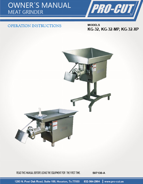
OPERATION INSTRUCTIONS MODELSKG-32, KG-32-MP, KG-32-XP READ THIS MANUAL BEFORE USING THE EQUIPMENT FOR THE FIRST TIME. 507130-AKG-32MEAT GRINDERINSTRUCTIONS FOR OPERATION, SERVICE AND MAINTENANCE OF THIS EQUIPMENTI.-INTRODUCTION:Congratulations !,you have acquired a meat grinder,which is made of high quality long lasting materials that should give you years of trouble free operation and durable service.Before you unpack your new unit,please,read completely this manual.IMPORTANT!:it is of vital importance that you or any person that will operate this unit thoroughly read this manual.WARNING!:This meat grinder is designed to cut food products and if it is not used and maintained properly for optimum safety,it could become dangerousThis equipment must be connected to a thermal connection,not use the equipment if it is not properly grounded.The appliance is not be used by persons (including children)with reduced physical,sensory or mental capabilities,or lack of experience and knowledge,unless they have given supervision or instruction.Children being supervised not play with the appliance.Never perform service, cleaning or maintenance on this unit while connected to a power source.Never use hands or fingers to feed products directly into the bowl area, always use the pusher included in the equipment.Do not leave the machine unattended while in operation & turn it off when it is not being used.CONTENTS:PAGE I.INTRODUCTION 1II.UNPACKING 2III.INSTALLATION 2IV.OPERATION4V.KEY ELEMENTS IN GRINDING QUALITY PRODUCT 4VI.CLEANING 6VII.MAINTENANCE6VIII.EQUIPMENT SPECIFICATIONS9II.-UNPACKINGWhile unpacking the machine take special care in removing these components to be assembled later.Make sure that all are accounted for *.*Note:for reference see “Meat grinder diagram for components ”(Central pages)III.-INSTALLATION:The Meat grinder is ready to use.Before to install it,you only need to verify the next points:1.Electrical installation meets the required specification of the equipment.2.Place has an adequate illumination and leveled floor/work table (The meat grinder already includes leveling support legs).3.Room is clean and meets the hygienic conditions for food processing.MEAT GRINDERKG-32The grinding unit includes:Also:1Headstock (10)1Pusher (1)1Worm (13)1Product tray (2)1Ring (17)1Bottle with mineral oil (24)-Approved by the Food and Drug Administration-.1Blade or kinfe (15)1Plate (16)4Support Legs (4)IMPORTANT!The equipment must be correctly grounded to prevent possible damage by electrical shock.IMPORTANT!:Wash the unit before using for the first time,specially the grinding unit.Also use the included food grade mineral oil to lubricate the plate (19)and knife (18)–See Cleaning section for more details.MEAT GRINDER KG-32WARNING!:This meat grinder is designed to cut food products and if it is not used andmaintained properly for optimum safety,it could become dangerousFIG.3 WORM ROTATION Before completing the electrical connection,check the worm(13)rotation.When the ON button is pressed,the worm must rotate counter clockwise,seeing the equipment in front.If the worm rotates clockwise,push the stop button and unplug the equipment.Interchange2of3incoming power supply wires.(See fig.2) Reconnect the grinder to the power supply,turn it on and verify the rotation again.If the correct operation is confirmed,fix the connection to the power supply.If you have any question regarding the connection of the equipment,contact to your authorized dealer.The above procedure only applies to grinder with three phase connection.HOW TO REMOVE GRINDING UNIT.1.-Remove the ring(17)turning it counterclockwise and extract the plate(16),Knife(15)and worm(13).2.-Unscrew the headstock knob(7)(see Fig4)to be able to remove the headstock(10).Reverse the steps and sequence to install the grinding unit again.Taking special attention to the next points:a)After assembling the headstock(10),screw the headstock knob(7)to fix the headstockb)The knife(15)must be inserted into worm’s shaft.The sharp end must face forward.c)Place plate(19)centered against knife(18)assuring the notch matches the Headstock’s inserted pin.FIG.4 POSITION FOR LEVER HANDLEIMPORTANT!:Before locking the headstock knob,be sure that both headstock(10)andtransmission cover(6)are joined with no gap between them.IMPORTANT!:Do not assemble the whole unit at the same time,this could damage the gears of transmission.Assembling component by component extends the life and guarantee the correct operation of the headstock and its components.MEAT GRINDERHOW TO INSTALL THE PRODUCT TRAY.1.-Place the hole of the tray (2)over the top of the headstock (10),use the guides under the tray to locate it in the correct position,tight both tray knobs to keep it in place,(be sure the tip of the knob screw fits in the Indention made in the headstock).2.-Place the pusher (1)into the safety guard.V.-KEY ELEMENTS IN MIXING/GRINDING QUALITY PRODUCTMODELS:M-32,M-32-3The meat grinder can grind at a rate of 55lb/min (25kg/min)at the first grinding using a 3/8”plate (not provided)and 28lb/min (13kg/min)for the second grinding.MODELS:M-32-5The meat grinder can grind at a rate of 63lb/min (29kg/min)at the first grinding using a 3/8”plate (not provided)and 30lb/min (14kg/min)for the second grindingTo extend the life of the equipment and get high quality product is recommended the next tips:▪Periodically verify the plate (16)and knife (15)sharp.▪Grinding Unit must be free of food debris.▪The tension on the head ring should be firm but not too tight.Over tightening can lead to excessive friction,motor wear and/or poor product appearance.▪Clean the grinding unit (including headstock)after use by removing it from the equipment.▪Keep the equipment in a clean and sanitary condition while is not being used.▪It is recommended that meat used for grinding is between 1°C a -3°C (33.8°F a 26.6°F)KG-32IV.-OPERATION:1.-Before starting,move to the correct work position –at sides of meatgrinder –(see Fig.5).2.-Turn on the machine.3.-Place product on the rear of feed tray (2).4.-Feed the product into the opening of the Headstock (10).5.-Using only the provided pusher (1),push the product without forcing it.FIG.5 WORKING POSITIONMEAT GRINDER1.-Utilize 3/8” plate or bigger for first grinding.KG-32CAUTION!:Usage caution and recomendation for grindingIMPORTANT!:Potential damge to equipment may occur if smaller plate is utilized for first grinding.Fig. A. The size plate is located on the edge2.-For a second grinding is possible to use a 3/16” plate or smaller.WARNING!:Do not use smaller plates than 3/8” in the first grinding to avoid equipment damagesIMPORTANT!:For the first time usage you must grind at least 2pounds of scrap clean product to remove any metallic or foreign debris.IMPORTANT!:This equipment has the capability of grind different kinds of food as long as it does not have a sticky consistency and/or prone to harden in the process, since it could get stuck on the components and potentially get jammed (e.g. hydrated chickpea, hydrated corn, food with pasty consistency, etc.)MEAT GRINDERVI.-CLEANINGFor cleaning the Grinding Unit,follow the next procedure:1.Disassemble main components as explained before on the installation section.ing a soft bristle brush not provided -See Fig 4,clean with adequate detergent each component,specially inside headstock (10)to eliminate waste and debris of food.3.Wash every component with plenty of water.4.Dry completely.Don't let soap cleaners dry on the surface.5.It is important after doing this procedure,to lubricate the knife (15)and plate (16)with the included mineral oil.Assemble again.VII.-MAINTENANCEThis equipment is designed to have a minimal maintenance,but,it ´s important to check the next points:1.The knife (15)and plate`s hole (16)always must have sharp edges.Replace them after certain period of use or if you notice the quality of the grinded meat is not as fine as the first time.2.Replace the knife and plate when assembly becomes loose even though the Ring (17)is totally tight.3.If the power cord (3)or the plug is damaged,it must be replaced by an authorized service technician or qualified personnel to avoid risk of electric shock.4.-Lubricate the entrance of the headstock in the transmission cover when if you see that the approved grease (24)has been consumed by use or cleaning.Apply only food contact approved grease contained in the bottle.It is important to always keep lubricated this area to be easy the disassembling of headstock.5.-The gear box of this grinder is sealed and should be repaired or opened only by approved technician,the transmission oil should be changed at least every two years of normal operation.IMPORTANT!:Avoid use of abrasive cleaners,acid,fibers,chlorides (such as chlorine bleach),on stainless steel surfaces will cause pitting,corrosion,and metal discoloration.Allowing salty solutions to evaporate and dry on stainless steel may also contribute to corrosive conditions.KG-32FIG.6 TIP FOR CLEANING ROUGHNESS PARTSCAUTION!:Always unplug or disconnect the machine from the power supply before cleaning or perform any maintenance.MEAT GRINDERGUIDE TO SOLVE TECHNICAL PROBLEMSKG-32PROBLEMSN O T U R N O NN O G R I N DE X C E S I V E N O I S EO I L S P I L LH E A D S T O C K G A P /M O V I N GH E A D S T O C K H O TVerify the electrical features (Current, Voltage, Etc) X Change the motorX Verify the electrical connection X XChange the switch X Verify the applied voltageXX Regulate the current (AMPS) on the thermal Relay X Change Knife/Plate XX Change gearsX Verify oil in transmission boxXChange the oil seal to transm. box and/or gear cover X Change the gasket to gear coverXRemove and assemble the headstock again XAvoid operating the meat grinder without product X Change nylon washer from the wormXParts to check and replaceFrequency of inspectionLifetime RemarksKnife (15) and plate (16)Monthly 3 monthsIt depends of use. If the grinded meat is not as fineas the first time, replacement is required.Transmission oil(See inside cabinet for oil type)Yearly 2 yearsCheck the oil level and appearance. If color of oil istotally dark, it needs replacement.Worm (13) headstock (10)Yearly 4 to 5 yearsIf assembly between these both components is loose(0.150” or more) the worm must be replaced.Power switch (9)MonthlyDepends of useThe feeling while pushing the power switch must be firm. If you notice excessive movement, you need toreplace it.THOSE ARE PARTS THAT NEED TO BE CHANGED AFTER SPECIFIC TIME OF USEMEAT GRINDERSTAINLESS STEEL SPECIAL CAREThis is a guideline of cleaning methods for stainless steel.KG-32 Requirement Suggested MethodRoutine cleaning of light soiling Wash with Soap or detergent in warm clean water. Apply with a clean sponge, soft cloth or soft-fiber brush then rinse in clean water and dry.Fingerprints Use Detergent.Rinse with warm water. Dry totallyWatermarksUse clean rinsing water, such as reasonable quality potable (tap) water. Drying marks may be avoided using an air blower or wiping with clean disposable wipes.Grease marksUse clean rinsing water ,you could add white vinegar or soft water solution. Rinse with warm water again and dry.Rust stainsWash surface with CLR (calcium, lime & rust remover) type cleaner. Use not acid and recommended solution. Apply using a soft non-abrasivesponge. Rinse surface thoroughly with clean soft water after application.Dirt and debris Wash surface with a mild liquid soap. Apply using a soft, non-abrasive cloth. Rinse surface thoroughly with clean soft water.MEAT GRINDERVIII.-EQUIPMENT SPECIFICATIONA) ELECTRICAL (Depends on your model. See ID plate)B) GENERAL DIMENSIONS.C) ELECTRICAL DIAGRAMThe electric diagram for this unit is located inside the cabinet.WARNING!:The cabinet for this equipment must be opened by qualified personnel only.For any problem or doubt related to electric specifications and connections,please call to your authorized dealer.KG-32MOTOR3HP (2.2 kW)Phases 13Voltage 220 V~230V~220 V3~230 V3~380V3~Frequency 60Hz 50 Hz 60 Hz 50Hz 50 Hz Current16.8 A (16 A*)16.8 A8.8 A (8 A*)8.6A4.4AMOTOR3HP (2.2 kW)Phases 1**3Voltage 220 V~220 V3~230 V3~380 V3~220 V~Frequency 60Hz 60 Hz 50 Hz60Hz Current26 A13.6 A (14.2 A*)14.2 A8.1A 26 A **Not available in USA*For Mexico42.91” (109 cm)23.62”(60 cm)9.84”(25 cm)21.25” (54 cm)Fig.7 Equipment general dimensions.KG-32 MEAT GRINDERMEAT GRINDER DIAGRAM FOR COMPONENTS (SEE CENTRAL PAGES)ITEM DESCRIPTION QTY 1PUSHER12PRODUCT TRAY13POWER CORD14ALUMINIUM LEGS45CABINET16TRANSMISSION COVER17HEADSTOCK KNOB18RUBBERS29SWITCH (INTERRUPTOR)110HEADSTOCK111REAR ROD112NYLON WASHER (M32)113WORM114FRONT ROD115KNIFE116PLATE117HEADSTOCK RING118SAFETY GUARD119BRONZE WASHER M32120TRAY KNOBS221DEFLECTOR KNOB122DEFLECTOR123MOTOR (3HP OR 5HP –NOT SHOWN)124FOOD CONTACT APPROVED GREASE BOTTLE1THANKS FOR READING THIS MANUAL. IF YOU HAVE ANY DOUBT REGARDING THE OPERATION OF THIS MEAT SAW, PLEASE CONTACT TO YOUR PRO CUTAUTHORIZED DEALER.。
小型绞肉机的设计

目 录摘要 (3)ABSTRACT (4)第1章 绪 论 (5)第2章 我国肉制品的生产加工与发展趋势 (6)2.1、 我国肉制品加工现状 (6)2.2.我国肉制品的发展趋势 (6)第3章 结 构 及 工 作 原 理 (9)3.1绞肉机的结构 (9)3.1.1送料机构 (9)3.1.2切割机构 (9)3.1.3驱动机构 (9)3.2绞肉机的工作原理 (10)第4章 螺旋供料器的设计 ....................................................................................... 错误!未定义书签。
第4章 螺旋供料器的设计 (11)4.1绞笼的设计 (11)4.1.1绞笼的材料 (11)4.1.2螺旋直径 (11)4.1.3螺旋供料器的转速 (12)4.1.4螺旋节距 (12)4.2绞筒的设计 (12)第5章 传动系统的设计 (13)5.1电机的选择 (13)5.2带传动的设计 (14)5.2.1确定计算功率d P (14)5.2.2 选定V 带的带型 (14)5.2.3确定带轮的基准直径d d 并验证带速v (14)5.2.4 传动比 (15)5.2.5 确定V 带的中心距0a 和基准长度0d L (15)5.2.6 验算小带轮上的包角1∂ (15)5.2.7计算带的根数Z (16)5.2.8计算单根V 带的初拉力的最小值 (16)5.2.9 计算压轴力∂F (16)5.2.10带轮的结构和尺寸 (17)5.3齿轮传动设计 (17)5.3.1 选择齿轮类型、精度等级、材料及齿数 (17)5.3.2按吃面接触强度设计 (18)5.3.3按照齿根弯曲强度设计 (20)5.3.4.几何尺寸计算 (21)5.3.5校核齿面接触强度 (22)5.3.6校核齿根弯曲强度 (24)5.3.7齿轮及齿轮副精度的检验项目计算(大齿轮) (26)5.4轴的设计 (27)5.4.1 选择轴的材料 (27)5.4.2 估算轴端直径 (27)5.4.3 轴的机构设计 (27)5.4.4 轴上载荷的分析 (28)5.4.5 按弯矩合成应力校核轴的强度 (29)5.4.6 精确校核轴的疲劳强度 (29)第6章绞刀设计 (34)6.1绞刀的设计 (34)6.1.1刀刃的起讫位置 (35) (36)6.1.2刀刃的前角6.1.3刀刃的后角 (37)6.1.4刀刃的刃倾角 (38)6.1.5刀刃上任一点位量上绞肉速度 (39)6.1.6刀片的结构 (40)第7章生产能力分析 (42)7.1绞刀的切割能力 (42)7.2 绞肉机的生产能力G (42)7.3功率消耗N (42)第8章绞肉机的维护与保养 (44)8.1 绞肉机生锈去锈的方法 (44)8.2 绞肉机的使用方法 (44)8.3 绞肉机操作规程 (45)设计总结 (46)参考文献 (47)小型绞肉机的设计摘要本文论述了肉类加工机械—绞肉机的工作原理、主要技术参数、传动系统、典型零件的结构设计及生产能力分析。
绞肉机设计说明书

绞肉机设计说明书篇一:绞肉机设计说明书目录目录................................................................................................ 1 摘要 (4)第一章绪论 (5)第二章工作原理及结构 (6)2.1 绞肉机的结构 (6)2.1.1 送料机构 (6)2.1.2 切割机构 (6)2.1.3 驱动机构 (6)2.2 绞肉机的工作原理 (6)第三章螺旋供料器的设计 (8)3.1 绞笼的设计 (8)3.1.1 绞笼的材料 (8)3.1.2 螺旋直径 (8)3.1.3 螺旋供料器的转速 (8)3.1.4 螺旋节距 (9)第四章传动系统的设计 (10)4.1 电机的选择 (10)4.2 带传动的设计………………………………………………………………114.2.1 设计功率………………………………………………………………114.2.2 选定带型 (11)4.2.3 传动比………………………………………………………………114.2.4 小带轮基准直径 (11)4.2.5 大带轮基准直径 (11)4.2.6 带速验算 (11)4.2.7 初定轴间距 (11)4.2.8 所需带的基准长度 (11)4.2.9 实际轴间距 (12)4.2.10 小带轮包角 (12)4.2.11 单根V带的基本额定功率 (12)4.2.12 i?1时单根V带型额定功率增量 (12)4.2.13 V带的根数 (12)4.2.14 单根V带的预紧力 (12)4.2.15 作用在轴上的力 (13)4.2.16 带轮的结构和尺寸 (13)4.3 齿轮传动设计………………………………………………………………134.3.1 选择材料,确定?Hlim和?Flim及精度等级 (13)4.3.2 按接触强度进行初步设计 (14)4.3.2.1 确定中心距 (14)4.3.2.2 确定模数 (14)4.3.2.3 确定齿数 (14)4.3.2.4 计算主要的几何尺寸 (14)4.3.3 校核齿面接触强度 (15)4.3.4 校核齿根的强度 (17)4.3.5 齿轮及齿轮副精度的检验项目计算 (18)4.3.5.1 确定齿厚偏差代号 (18)4.3.5.2 确定齿轮的三个公差组的检验项目及公差值 (18)4.3.5.3 确定齿轮副的检验项目与公差值 (18)4.3.5.4 确定齿坯的精度 (19)4.4 轴的设计 (20)4.4.1 选择轴的材料,确定许用应力 (20)4.4.2 按扭转强度估算轴径 (20)4.4.3 设计轴的结构并绘制结构草图 (20)4.4.4 按弯扭合成强度校核轴径 (21)4.4.5 作转矩图………………………………………………………………234.4.6 求当量弯矩 (23)4.4.7 确定危险截面及校核强度 (23)4.5 联轴器的选用………………………………………………………………234.5.1 类型的选择 (23)第五章绞刀的设计 (25)5.1 绞刀的设计 (25)5.1.1 刀刃的起讫位置 (26)5.1.2 刀刃的前角 (27)5.1.3 刀刃的后角 (28)5.1.4 刀刃的刃倾角 (29)5.1.5 刀刃上任一点位量上绞肉速度 (30)5.1.6 绞刀片的结构 (31)第六章生产能力分析………………………………………………………………336.1 绞刀的切割能力 (33)6.2 绞肉机的生产能力 (33)6.3 功率消耗..............................................................................33 设计总结..........................................................................................35 致谢.............................................................................................36参考文献 (37)【摘要】本文论述了肉类加工机械—绞肉机的工作原理、主要技术参数、传动系统、典型零件的结构设计及生产能力分析。
手动绞肉机毕业设计

手动绞肉机毕业设计手动绞肉机毕业设计一、引言现代社会,随着科技的发展,电动肉绞机已经逐渐取代了传统的手动绞肉机。
然而,手动绞肉机作为一种传统的厨房工具,仍然具有一定的市场需求。
本文将探讨手动绞肉机的设计和制作,以满足一部分人对于传统工具的喜好和需求。
二、设计理念手动绞肉机的设计理念是简单、实用和可靠。
与电动绞肉机相比,手动绞肉机不需要电源,操作更加方便灵活。
设计师应该注重提高手动绞肉机的工作效率和使用体验,同时要确保产品的安全性和耐用性。
三、结构设计手动绞肉机的结构主要包括机身、转动机构和切割机构。
机身应该采用坚固的材料,如不锈钢或铸铁,以确保产品的稳定性和耐用性。
转动机构应该设计成易于操作和维护的结构,例如使用曲柄和齿轮传动系统。
切割机构应该采用锋利的刀片,以确保肉类能够被均匀绞碎。
四、材料选择手动绞肉机的材料选择非常重要,因为它直接关系到产品的质量和使用寿命。
机身可以选择不锈钢或铸铁,这些材料坚固耐用,不易生锈。
转动机构的齿轮可以采用高强度的钢材,以确保传动的可靠性和耐用性。
刀片可以选择优质的不锈钢材料,以保证切割的效果和卫生安全。
五、性能改进为了提高手动绞肉机的性能,可以考虑以下几个方面的改进。
首先,可以增加机身的重量和稳定性,以减少使用过程中的晃动和噪音。
其次,可以改进转动机构的传动效率,减少操作的力度和时间。
再次,可以优化切割机构的刀片设计,以提高绞肉的效果和速度。
最后,可以增加产品的附件,如不同规格的刀片和容器,以满足不同用户的需求。
六、市场前景尽管电动肉绞机已经成为市场的主流产品,但手动绞肉机仍然具有一定的市场需求。
一方面,一些用户喜欢传统工具的使用感受和操作方式。
另一方面,手动绞肉机在一些特殊场合和户外环境下更加适用,如野外烧烤和露营活动。
因此,手动绞肉机作为一种传统工具,仍然具有一定的市场前景。
七、总结手动绞肉机作为一种传统的厨房工具,虽然在现代社会中逐渐被电动绞肉机取代,但仍然具有一定的市场需求。
摩飞mr9401说明书
要把菜做好做美味,食材新鲜与否是一个关键的点,但是同样的,刀工、耐心、手艺三者也是缺一不可。
别再这么辛辛苦苦剁馅儿啦摩飞绞肉机能让你“偷懒”的同时也做出一桌好菜快来种草吧~【新款摩飞食物处理器】在之前绞肉馅儿、切蔬菜、剁酱料、做辅食、打坚果的基础上,还多了剥蒜的功能,这可把顿顿标配大蒜的我老公激动坏了。
新款机器配了3个不锈钢套盆,这让我们在操作的过程中特别方便。
比如我前几天包饺子,一个盆绞肉,一个盆切菜,再也不用中途换容器洗盆了,效率都提升了,用完直接扔进洗碗机就行。
平时不用这个机器时,这3个盆也能当个做菜的备料盆,or做西点时的烘培盆,一物多用,特实惠方便。
而且,不锈钢的材质比较耐用,咱在厨房免不了有粗心大意的时候,这回就不怕偶尔的磕碰啦。
这3个盆是可以一个套一个,摞在一起收纳的,跟俄罗斯套娃似的,非常省空间,好收纳,所以,这款食物处理器还有个别名,叫“套娃式绞肉机”。
不用的时候,把它随便放在一个抽屉里or柜子里,就OK了,很适合咱“寸土寸金”的厨房。
旋风速搅,解放双手热衷于美食的料理达人几乎天天与厨房打交道,在追求菜品品质的同时,对制作的速度也有自己的追求。
摩飞绞肉机能快速将肉块打成肉馅,这强劲的动力和飞快的速度直逼比爱情来得更快的龙卷风。
双层4维刀刃谁说绞肉机只能做饺子馅?S型双层四刀设计让切割更加立体均匀,肉泥也能搅打得更加细腻,哪怕是肥膘肉摩飞绞肉机也能给你安排得妥妥地~360°全方位绞肉,让食物无处可逃,四面八方全是刀影,制作出的肉馅丸子Q弹十足。
纯铜电机超耐久很多料理棒和辅食机的噪音声音大得简直像在拆家轰隆轰隆的声音,把料理的好心情统统都打碎了。
而摩飞绞肉机采用了纯铜电机,350W大功率强动力,稳定低噪,降热性能良好。
因此它的使用寿命也会更持久,刀头、电机、搅拌碗,三者完全独立,让清洗更加简单快捷、安全可靠。
绞肉完成之后拿出刀片,还可以直接在里面调馅,设计贴心且人性化如果你们家爱吃包子,饺子,馄饨,馅饼,鱼丸,虾丸,猪肉脯,香肠……这种需要馅儿的食物,那太值得收一个了。
冻肉绞肉机操作说明

绞肉机一、概述绞肉机依靠螺杆将料斗箱中的原料肉推到预切板处,通过螺杆的旋转作用,使得绞刀与孔板产生相对运动,从而将原料肉切成颗粒形状,以消除原料肉种类、软硬、纤维粗细不同的缺陷,确保了肉馅的均匀性。
JR-130双速绞肉机主体全部采用不锈钢制作,设备结构合理、造型美观、机械性能稳定可靠、清洁卫生、噪音小。
该机可以绞切鲜肉、冻肉。
用户可根据工艺要求选配不同规格的孔板和选择适宜的绞肉速度(快速或慢速),加工出最理想的肉馅,以满足不同肉制品的加工需要,是替代进口同类产品的最佳选择。
二、技术参数三、安装与调试1、将绞肉机出料口支装在便于出料的方向。
调整活动地脚螺栓使机器水平,允许绞肉机出料口向下倾斜1°,以便于排出清洗水。
2、检查润滑部位是否注食用油,减速箱油位是否正常(详见结构图注油示意图)。
3、清洗料斗箱、绞笼、预切板、孔饭、绞刀、绞笼套、压紧套、绞笼外套螺母等零部件,并注食用油。
4、检查三角皮带松紧程度。
5、检查电气元件及机器部件螺栓是否松动.6、安装绞笼、绞笼套,拧紧锁紧装置,安装预切板、绞刀、孔板、压紧套、旋紧绞笼外套螺母.7、接通电源试车:瞬间点动慢速绞肉按钮,检查绞笼旋转方向〈从机器出料口方向看应为逆时针方向旋转).8、当绞肉孔扳选择在φ10以上时,安装绞肉系统顺序为:绞笼→绞笼外套→拧紧锁紧装置→预切板→绞刀→孔板(φ10以上任意1个)→压紧套→绞笼外套螺母,拆卸时顺序应相反〈详见结构图2). 9、当绞肉孔板选择在φ3、φ5或φ7 肘,安装绞肉系统顺序为:绞笼→绞笼外套→拧紧锁紧装置→预切板→绞刀→孔板φ13→绞刀→孔板(φ3、φ5、φ7任意1个)→压紧套→绞笼外套螺母,拆卸时顺序应相反(详见结构图2 ).四、操作方法1、把少量原料肉约15公斤,放在料斗箱绞笼出口处,按下慢速绞肉按钮,使肉品旋送到最外的孔板为止,停机并使机器反转约5转左右,再停机,然后拧紧绞笼外套螺母,使绞刀刃与孔板之间紧密连接,按下用户选择的快速或慢速绞肉按钮,将原料肉加入料斗内进行绞碎。
- 1、下载文档前请自行甄别文档内容的完整性,平台不提供额外的编辑、内容补充、找答案等附加服务。
- 2、"仅部分预览"的文档,不可在线预览部分如存在完整性等问题,可反馈申请退款(可完整预览的文档不适用该条件!)。
- 3、如文档侵犯您的权益,请联系客服反馈,我们会尽快为您处理(人工客服工作时间:9:00-18:30)。
手摇绞肉机设计说明书
手摇绞肉机用于家庭手工绞肉,操作简单、使用方便。
它主要由外壳筒体、挤盘、螺旋轴、刀片、摇杆、前盖和后盖组成。
手摇绞肉机工作原理
工作时,将肉料放入绞肉机的送料口中,由于肉料本身的重力和螺旋轴的转动,把肉料连续的送往绞刀口进行切碎。
因为螺旋轴的螺距后面比前面小,而且螺旋轴的直径后面比前面大,这样对肉料产生了一定的挤压力,这个力迫使已切碎的肉料从挤板上的孔眼中挤出,这样就得到了肉沫。
外壳筒体的设计
机架与螺旋轴同锥度,有利于螺旋轴与机架的配合,防止空隙引起肉料的堆积。
送料口也采用漏斗的形式,有利于肉料的运送。
螺旋轴的设计
螺旋轴的螺距后面比前面小,而且螺旋轴的直径后面比前面大,这样对肉料产生了一定的挤压力,这个力迫使已切碎的肉料从挤板上的孔眼中挤出。
前盖的设计
前盖的圆周上有突棱,这样螺旋时增大了摩擦有利于螺旋前盖。
前盖还限制了挤盘的左右移动,防止挤盘的掉落。
刀片与挤板的设计
刀片采用三角形形状,增大强度,有利于切碎。
挤盘采用对称的圆形孔眼以利于受力均匀,增加使用效率,提高绞肉机寿命。
工程图和主要的尺寸
手摇绞肉机操作简单、使用方便。
它能提高用户的工作效率,节省用户的体力,是一个很有发展前景的简单实用的机器。