本原cspm5500说明书
理研计器指示警报单元RM-5000 系列使用说明书

PT1C-1051指示警报单元RM-5000系列使用说明书邮编:174-8744 日本东京都板桥区小豆泽2-7-6 网页http://www.rikenkeiki.co.jp/目录1产品概述1-1.前言 (2)1-2.使用目的 (2)1-3.危险、警告、注意、注记的定义 (2)1-4.CE标志规格的确认方法 (3)2安全重要事项2-1.危险事项 (4)2-2.警告事项 (4)2-3.注意事项 (5)3产品构成3-1.主机及附件 (6)3-2.外形图 (7)3-3.各部的名称和功能 (8)3-4.框图 (12)4使用方法4-1.使用之前 (13)4-2.安装场所相关的注意事项 (13)4-3.系统设计上的注意事项 (14)4-4.安装方法 (16)4-5.配线方法 (18)5操作方法5-1.起动准备 (27)5-2.基本动作流程 (27)5-3.启动方法 (28)5-4.关于各种模式 (29)5-5.检测模式 (31)5-6.警报测试模式 (32)5-7.用户模式 (33)5-8.结束方法 (37)6各种动作及功能6-1.气体警报动作 (38)6-2.故障警报动作 (41)6-3.外部输出动作 (42)6-4.关于各种功能 (44)7保养点检7-1.点检的频度和点检项目 (46)7-2.定期点检模式 (47)7-3.气体校准方法 (64)7-4.清扫方法 (69)7-5.保险丝的更换方法 (69)8关于储存、移设及废弃8-1.进行储存或长期不使用时的处理 (70)8-2.移设或重新使用时的处理 (70)8-3.产品的废弃 (70)9故障检修 (71)10产品规格10-1.规格一览 (73)10-2.产品的构成 (74)11术语的定义 (75)3.产品构成3-1.主机及附件<主机(RM-5000系列)><附件>EC-5002、EC-5002i、OX-5002、OX-5002i、RM-5002、RM-5002i、RM-5003、RM-5003T ·使用说明书与交付台数无关,1个系统1份GP-5001、NC-5001、NC-5001W、NP-5001 SP-5001、GH-5001、OX-50013-2.外形图电源指示灯 1st 警报指示灯 2nd 警报指示灯错误指示灯(故障指示灯)显示部端子台面板固定金属件图中的编号名称功能①POWER开关电源开关。
STI Group Model 5500 太阳能动感应安全灯说明书

© 2006 STI Group, Inc.For further information, including parts, warranty repair or general inquiries, please contact the STI Group, Inc. at:Intellectual PropertyThis product is covered by one or more international and US patents pending.All logos, designs and colors are copyrights and trademarks of STI Group, Inc. All rights reserved 2006Please register your product online at our website:/registrationUSA Corporate OfficeTel:847.918.8558Address:1203 Loyola Drive •Libertyville, IL 60048Email:********************Website:STI Group Inc. Locations:CHICAGO LOS ANGELES ATLANTA SHENZHEN, CHINAModel 5500Solar Motion Sensor Security LightPowerful 10 Watt Halogen Security LightCONTENTS1. I ntroduction2. Security instructions3. Components4. Mounting I nstructions5.Initial Charging Set-up6. Understanding the Motion Sensor Controls7. Adjusting Lamp Housing8. Replacing Bulb & Battery9. General Electrical and Safety Warnings10. Cleaning11. Storage12. Troubleshooting13. Technical Data14. Spare Parts15. One Year Limited WarrantyThese instructions relate ONLY to this Solar Motion Sensor Set and contain important information for using the product for the first time. Please keep these instructionsfor later reference. They should always accompany the product in the event of transfer to a new user.1. INTRODUCTIONThank you for purchasing this Solar Motion Sensor Security Light. You have purchased a product that complies with the latestand most up-to-date solar technology available.This product complies with the European and National Standards. The relevant certificates of conformity are held by STI Group.To preserve these standards and in order to maintain safety you should adhere to the instructions for use detailed in this manual.2. SECURITY INSTRUCTIONSIn the event of any problems arising or damage occurring as a result of misuse the manufacturers warranty will be deemed cancelled. The manufacturer is not responsible for any claims or damages arising from the misuse of this product.For safety reasons and in order to maintain standards (CE) you are prohibited from altering or changing any component in this Solar Motion Sensor Security Light.Please follow the instructions very carefully.For commercial applications due care and attention must be paid to the Health and Safety Standards in your jurisdiction.Figure AFigure B3. COMPONENTS4. MOUNTING INSTRUCTIONS1.Mounting Bracket2. AdjustmentSupport3. Power Cable4. Solar Cell MountingScrews (x3)5. Solar Cell6. Main Battery Unit7. Main Unit8. Mounting Screws (x2)9. P R Sensor10. AUTO / OFFSwitch11.AC-DC AdaptorInterface (requires9VDC/500mA outputadaptor (not included)12.TransparentLight CoverHOW TO DETERMINE WHERE TO MOUNTYOUR SOLAR MOTION SENSOR SECURITY LIGHTNote:In the FIGURE B position, it is important not to let rainenter the main unit. Make sure it is mounted in a covered area.Please note that: DIRECT SUNLIGHT is important for theoperation of SOLAR MOTION SENSOR SECURITY LIGHT. Themore direct sunlight the solar cell receives in daytime, the longerthe light will operate. (Else, you have to charge it through theAdaptor hole on the main body’s side)Main Unit:The main unit contains the lamp (10Watt/6V G5.3halogen bulb), motion sensor and battery (sealed Lead-AcidRechargeable battery, 6V, 4Ah). When determining where tomount this unit, consider that the motion sensor has a detectionscope of around 39 feet (in front of the light) to 26 feet(aroundthe light). See FIGURE C on the next page. Sensor has ahorizontal field of vision of 180°. T o mount the unit vertically as asecurity light, attach the unit to a solid surface as shown in FIGUREA. T o mount the unit horizontally as convenience lighting, attachthe unit as shown in FIGURE B. Use the two wood/ sheet metalscrews provided in the package.Solar Cell:The solar cell is the main power source for theSOLAR MOTION SENSOR SECURITY LIGHT. It converts thesunlight’s energy into electricity that charges the battery in mainunit. It requires DIRECT SUNLIGHT onto the surface of solar cellfor as long as possible during the daytime.SOUTHSOUTHSOUTHSolar Panel Unit Lighting/Sensor UnitUse the three wood/sheet metal screws provided in the package (#4 on parts list) to mount the solar cell unit onto a solid surface. Make sure it is mounted fixed into the solid surface.You can adjust the angle of the solar cell by moving the adjustment bracket to the appropriate hook on themounting base. It should face as much DIRECT SUNLIGHT as possible during the daytime.At last route the solar cell’s power cord to the main unit and plug it into the side hole for solar cell. Additionally, the side hole for adaptor is for the secondary charging during raining season.Important: if the main unit is mounted horizontally, it must be mounted in a covered area so rain water can not get into the unit through the exposed vents.5. INITIAL CHARGING SET-UPAfter you successfully installed your SOLAR MOTION SENSOR SECURITY LIGHT, you are almost ready for carefree operation with a few final steps:Initial 3-days Charge:On the main unit there is a slide switch with 2 positions:• OFF • AUTOAUTO - Position for normal operationOFF - Position for delivery or long periods of non-usePosition for initial 3-day charge before first use. Then, turn the slide switch to OFF position. The solar cell will charge the battery without activating the unit. Leave the switch in this position for 3 sunny days to ensure that the battery has a full charge for motion sensor adjustment and normal operation.6. UNDERSTANDING THEMOTION SENSOR CONTROLSAfter the initial 3-day charge, turn the switch to AUTO position.In the motion sensor the following 3 specifics TIME / SENS /LUXare pre-set in factory. TIME -Duration time of the light to run after motion isdetected in the field, the duration time is set to 30 seconds. On a fully charged battery, it can light up to 300illuminations of 30 seconds each. Note: Once the light is activated by the PIR sensor, any subsequent detection will restart the timed period again from the beginning.Vertical MountingSet-upHorizontal MountingSet-upSlide SwitchAC-DC Adaptor Interface. Requires 9VDC/500mAoutput adaptor (not included).SENS -The infra-red sensor’s detection range is preset todetect movement from 26 to 39 feet away. This can be affected by environmental temperature. The lower environmental temperature and humidity, the more sensitive the PIR sensor.Refer to FIGURE C for detection range.LUX -The Lux control module has a built-in sensing device (photocell) that detects daylight and darkness. The control level is pre-set to 30 LUX, which denotes the dawn or dust environmental level. When the environment is darker than 30LUX, the sensor will start to work.Walking test:Point the motion sensor to facing the area you want to detect motion in. Walking slowly in its detection area when it isevening or when the environment is dark, the built-in infra-red sensor detects movement by measuring the radiation given off by the human body and then turns on the light. Test the coverage of the area by walking around slowly until the light does not switch on.7. ADJUSTING LAMP HOUSINGPoint the lamp housing facing the area you wish to illuminate.8. REPLACING BULB & BATTERYCaution:When replacing the bulb or battery, the slide switch on the main unit must be in the OFF position.Bulb Replacement:Depending on the amount of use, the bulb in your SOLAR MOTION SENSOR SECURITY LIGHT is designed to have an average life of about one year. When it becomes necessary to replace the bulb, you can obtain a replacement from location agent. The old bulb can be easily replaced by popping the transparent light cover (#8 in parts list) off with a screwdriver (there is a slot at one end of the cover) and pulling the bulb from its base. Reverse this procedure with the new bulb to reassemble.IMPORTANT:The bulb will be hot when the light is on, please let the bulb cool when replacing the bulb. Be extremely careful when handing the bulb, especially if it is broken. Also, do not touch the bulb with bare hands / fingers as this will shorten bulb life.)Battery Replacement:The battery in your SOLAR MOTION SENSOR SECURITY LIGHT is designed to last for about 3 years. When it becomesnecessary to replace the battery, you can obtain a replacement from your local distributor or STI Group.Figure CSENSORDETECTION RANGE 26 FT.39FT.。
5500控制器操作手册2004 edition

-1-
目录
第1节-概论 编制目的. . . . . . . . . . . . . . . . . . . . . . .. . . . . . . . . . 4 其他安全须知指示 . . . . . . . . . . . . . . . . . . . . . . . . . . . . . . . . . . . . .5 附加的安全要求 . . . . . .. .. .. . .. . . . . . . . . . . . . . . . . . 5 储存. . . . . . . . . . . . . . . . . . . . . . . . . . . . . . . . . . 6 操作.. . . . . . . . . . . . . . . . . .. . . . . . . . . . . . . . . . . 6 温度和通风. . . .. . . . . . . . .. . . . . . . . . . . . . . . . . . . . 6 输入电压. . . . . . . . . . . . .. . . . . . . . . . . . . . . . . . . . 6 接地线 . . . . . . . .. .. . . . . . . . . . . . . . . . . . . . . . . . 6 电源线 . . . . . . . . . . . . . . . . . . . . .. . . . . . . . . . . . . 6 输出/马达断电 . . . . . . . . . . . . . . . . . . . . . . . . . . . . . . 7 模拟信号.. . . . . .. . . . . . . . . . . . . . .. . . . . . . . . . . . 7 系统区域接线图.. . . . . . . . . . . . . . . . . . . . . . . . . . . . . 7 传感器和控制线路. . . . . . . . . . . . . . . . . . . . . . . . . . . . . 7 第2节-安装 位置 . . . . . . . . . . . . .. . . . . . . . . . . . . . . . . . . . . 11 安装 . . . . . . . . . . . . . . . . . . . . . . . . . . . . . . . . .. . . . . . . .11 使设备运转. . . . . . . . . . . . . . . . . . . . . . . . . . . . . . . . .12 第3节-设备与功能 一般注意事项 . . .. . . . . . . . . . . . . . . . . . . . . . . . . . . 13 启动电源. . . . . . . . .. . . . . . .. . .. . . . . . . . . . . . . . . 13 设定 . . . . . . .. . . . . . . . . . . . . . . . . . . . . . . . . . . . 14 感测器设定 . . . . . . . . . . . . . . .. . . . . . . . . . . . . . . . . .14 水泵设定. . . . . . . . . . . . . . . . . . . . . . . . . . . . . . . . . .. . . . . . . .18 系统设定. . . . . . .. . . . . . . . . . . . . . . . . . .. . . . . . .19 衔接/跳脱(STAGE/DESTAG)设定. . . . . . . . . . . . . . . . . . . . .19 PID设定 . . . . . .. . . . . .. . . . . . . . . . . . . . . . . . . . . . 21 警报设定 . . . .. . . . . . . . . . . . . . . . . . . . . . . . . . . .21 交替运转设定 . . . . . . . . . . . .. . . . . . . . . . . . . . . . . . 22 旁通设定 .. . . . . . . . . . . . . . . . . . . . . . . . . . . . . . . 22 变频器设定. . . . . . . . . . . . . . . . . . . . . . . .. . . . . . . 22 日期/时间设定. . . . .. .. .. . . . . . . . . . . . . . . . . . . . . . . 23 设定密码. . . . . . . .. ... . . . . . . . . . . . . . . . . . . . . . . 24 设定输入/输出. . .. . . . . . . . . . . . . . . . . . .. . . . . . . . . 24 通讯设定. . . . . . .. . . . . . .. . . . . . . . .. . . . . . . . . . . 26 特殊功能. . . . . . . . .. . . . . . . . . . . . .. . . . . . . . . . . . 27 测试输入& 输出. . . . . . . . . . . . . . . . . . . . . . . . . . . . . 28 第4节 操作 AO . . . . . . . . . .. . . . . . . . . . . . . . . . . . . . . . . . . . 32 A1 . . . . . . . .. . . . . . . . . . . . . . . . . . . . . . . . . . .33 B3 . . . . . . . . . . . . . . . . . . . . . . . . . .. . . . . . . . 34 C0 . . . . . . . . . . . . . . . . . . . . . . . . . . . . . . . . . .的Techlnologic5500控制器,此设备 是因袭了其他Techlnologic的控制面板形式,同时,又包含了许多只有ITT Bell&Gossett才具备的,独创、新颖、专有的特征。其中一部分特征,在 此需要特别强调。
SM5000串行板类用户手册

目录目录 (1)第一章SM 5000串行控制系统功能介绍 (5)1.1. 基本功能列表 (5)1.2. 特殊功能列表 (7)1.3. 安全保护功能列表 (10)1.4. 可选功能列表 (10)第二章SM 5000串行控制系统板类产品型号 (11)2.1.产品型号命名方法 (11)1. 基本规则 (11)2. 主控电脑板、轿厢电脑板、轿厢扩展板、外呼板命名 (11)2.2. SM5000串行系统板类产品型号列表 (11)第三章SM 5000串行控制系统构成与部件介绍 (12)3.1. 系统结构框图 (12)3.2. 系统主要部件性能指标 (12)3.2.1性能特点 (13)3.2.2. 适用范围 (13)3.2.3. 参照标准 (13)3.2.4. 电源规格 (13)3.2.5. 工作温度 (13)3.2.6. 检测指标 (13)3.3. 系统主要部件分类介绍 (14)3.3.1. 主控电脑板SM 5000-V2 (14)3.3.2. 轿厢电脑板SM 5000-02A (17)3.3.3. 轿厢扩展电脑板SM 5000-02B (20)3.3.4. 外召及显示电脑板SM5000-04A (21)第四章SM 5000串行控制系统的安装 (24)4.1. 重要提示 (24)4.2. 到货检查 (24)4.3. 系统安装 (24)4.3.1. 安装技术要求 (24)4.3.2. SM 5000系列部件安装 (24)4.3.3. 系统其它部件安装 (25)4.3.4. 控制系统接地 (26)第五章SM 5000串行控制系统参数设置 (27)5.1. 概述 (27)5.2. 系统菜单结构与流程 (28)5.2.1. 主菜单 (29)5.2.2. 通讯状态菜单 (29)5.2.3. 密码校验界面 (29)5.2.4. 监视菜单与参数设置菜单 (29)5.2.5. 菜单设置操作提示 (31)5.3. 监视参数菜单设置与操作 (31)5.3.1. 监视参数表 (31)5.3.2. 设置与操作 (31)1. 选层信息 (31)2. 层站信息 (32)3. 井道开关位置 (32)4. 输入输出 (33)5. 速度反馈 (33)6. 运行记录 (33)7. 故障记录 (34)8. 呼梯测试 (34)9. 输入信号 (34)10. 输出信号 (35)11. 轿厢信号 (35)12. 开/关门输入 (35)13. 通讯测试 (36)14. 软件版本号 (36)5.4. 基本参数菜单设置与操作 (36)5.4.1. 基本参数表 (36)5.4.2. 设置与操作 (36)1. 总楼层数设定 (37)2. 待梯层设定 (37)3. 系统时间设定 (38)4. 自动开门保持时间设定 (38)5. 开门延长时间设定 (38)6. 返基站时间设定 (38)7. 自动开梯时间设定 (38)8. 自动关梯时间设定 (38)9. 消防层设定 (39)10. 锁梯层设定 (39)11. 输入类型 (39)12. 轿厢输入类型 (41)13. 输出类型(暂时常开出点处理) (41)14. 层站显示设置 (41)15. 停靠层设置 (41)16. 开门延长使能设定 (41)17. 抱闸反馈检测使能设定 (42)18. 开门选择设定 (42)19.F参数 (42)5.5. 运行参数菜单设置与操作 (42)5.5.1. 运行参数表 (42)1. 电梯额定速度设定 (43)2. 电机额定转速设定 (44)3. 编码器脉冲数设定 (44)4. 检修运行速度 (44)5. 起动平滑速度设定 (45)6. 自救运行速度设定 (45)7. 单层运行速度设定 (45)8. 启动多段速时间设定 (45)9. 抱闸时间设定 (46)10. 加速斜率b1设定 (46)11.减速斜率b2设定 (46)12.S时间1—— P1设定 (46)13.S时间2——P2设定 (47)14.S时间3——P3设定 (47)15.S时间4——P4设定 (47)16. 零速设置 (48)17.零速时间 (48)18.平层微调 (48)19.平层调整 (48)20.试运行 (49)5.6. 特殊参数菜单设置与操作 (49)5.6.1. 特殊参数表 (49)5.6.2. 设置与操作 (49)1. 开/关门继电器保持时间设定 (50)2. 恢复出厂值 (50)3. 并联使能设定 (50)4. 群控使能设定 (50)5. 远程监控设定 (51)6. 贯通门方式 (51)7. 消防方式设定 (51)8. 并联梯号设定 (52)9. 多段速度值设定 (52)10. 减速距离设定 (54)11. 运行超时时间设定 (55)12. 开关门到位检测 (55)13. Inventer (56)5.7. 其它参数菜单设置与操作 (56)5.7.1. 井道自学习 (56)5.7.2. 参数保存 (56)5.7.3. 密码设置 (57)第六章SM5000串行控制系统调试与运行 (58)6.1. 重要提示 (58)6.2. 通电前检查 (58)6.3. 通电和检查 (58)6.3.1. 通电前确认 (58)6.3.2. 通电后检查 (59)6.4. 系统参数设定 (59)6.5. 慢车试运行 (60)6.5.1. 机房检修运行 (60)6.5.2. 轿顶及轿厢检修运行 (60)6.6. 井道自学习 (60)6.7. 快车试运行 (61)6.8. 电梯舒适感调整 (61)6.8.1. 起、制动曲线的调整(模拟量) (61)6.8.2. 对运行曲线的跟踪调整 (62)6.8.3. 电梯运行控制时序的调整 (62)6.8.4. 多段速度方式调整 (62)6.9. 平层精度调整 (65)6.10. 端站安装位置的确认 (65)第七章SM5000串行控制系统故障分析 (66)7.1. 检修运行条件 (66)7.2. 检修运行速度低、电流大 (66)7.3. 主控电脑板显示的速度不正确 (66)7.4. 通讯不正常检查 (66)7.5. 开关电源(5V/24V)异常 (66)7.6. 没有方向及抱闸输出信号的检查 (67)7.7. 电梯不关门 (67)7.8. 急停接触器触点状态与线圈状态不一致(ER02) (68)7.9. KMY接触器输出与反馈结果不一致(ER04) (68)7.10. 开闸故障(ER18) (68)7.11电梯运行方向与指令方向相反(ER30) (68)7.12. 门联锁接触器触点状态与线圈状态不一致 (69)7.13. 低速度换速距离大于单层间距(ER41) (69)7.14. 主控电脑板未收到变频器运行信号反馈(ER21) (69)7.15. 不能快车运行(ER25) (69)7.16楼层位置计数器错误(ER28) (69)附录. 参考故障代码表 (70)1. 系统故障代码表 (70)2.自学习故障代码表 (75)第一章SM 5000串行控制系统功能介绍1.1. 基本功能列表编号名称用途电梯动作说明备注1 自动运行(1)到站自动开门;(2)自动延时关门;(3)手动提前关门(门开未到延时关门时间时);(4)内选自动登记(防捣乱、误操作消除);(5)外召顺向自动截车;(6)外召反向最高(或最低)自动截车。
原子力显微镜(AFM)在石英薄片表面形貌分析中的应用

原子力显微镜(AFM)在石英薄片表面形貌分析中的应用杨丽;张佩聪;王建华;董万建【摘要】介绍了研究石英中杂质赋存状态的重要性以及原子力显微镜在石英表面分析中的应用,结果通过原子力显微镜我们能够看到石英表面颗粒分布均匀,结构致密,颗粒没有大尺度的起伏等表面结构,并且利用它高的分辨率得到了石英表面纳米级别的微观形貌,为后续的确定杂质赋存状态做了准备。
%The importance of studying the impurity occurrence state and the application of atomic force microscopy(AFM) in surface analysis of quartz were introduced.The quartz grains were well distributed and had compact structure and non-large scale fluctuation.The nanometer level micro-morphology was obtained using high resolution of AFM,which made preparation for the subsequent determination of impurities occurrence state.【期刊名称】《广州化工》【年(卷),期】2012(040)015【总页数】2页(P124-125)【关键词】原子力显微镜;石英薄片;形貌分析【作者】杨丽;张佩聪;王建华;董万建【作者单位】成都理工大学材料与化学化工学院,四川成都610059;成都理工大学材料与化学化工学院,四川成都610059;成都理工大学材料与化学化工学院,四川成都610059;成都理工大学材料与化学化工学院,四川成都610059【正文语种】中文【中图分类】O613我国是一个人口大国,同时也是一个资源消耗强国。
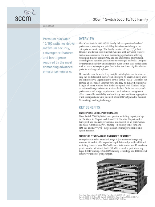
3Com Switch 5500 10 100系列用户手册说明书
3COM SWITCH 5500 FAMILY IN AN ENTERPRISE CAMPUS NETWORK5Suggested Service, Support and Training OfferingsNetwork Health CheckAn activity-auditing service focused on improving network performance and productivityIncludes traffic monitoring, utilization analysis, problem identification, and asset deployment recommendations Extensive report provides blueprint for actionNetwork Installation and Experts set-up and configure equipment and integrate technologies to Implementation Servicesmaximize functionality and minimize business disruptionFor large and complex sites, implementation services include personalized configuration, project management, extended testing and coaching on network administrationProject ManagementProvides extra focus and resources that special projects demand 3Com engineers manage entire process from initial specifications to post-project reviewUsing structured methodology, requirements are identified, projects planned and progress of implementation activities tracked3Com Guardian SM Maintenance Service This service provides comprehensive on-site support and includesadvance hardware replacement, telephone technical support and software upgrades 3Com Express SM Maintenance Service This service provides speedy access to: 3Com shipment of advance hardware replacements, software upgrades and telephone support 3Com UniversitySelf-paced and instructor-led technology and product courses, plus certification programs3Com Global Services offers the resources and talents of a major corporation plus more than two decades of experience in resolving network challenges and delivering business benefits to enterprises around the world.Global support with a personalized focus in the local language helps drive productivity and minimize expenses. Because 3Com understands both the technology and the business, we’re the partner you need, to maintain your competitive edge and remain strong.SERVICE AND SUPPORTWarranty3Com Limited Lifetime Warranty. For as long as the original end user owns the product, or for five years after 3Com discontinues the sale of the product, whichever occurs first.Hardware coverageCovers the complete unit including power supply and fan.In-warranty hardware replacement *Advanced Hardware Replacement of hardware for the duration of the warranty. In the US 48 contiguous states this is same-day ship with next business day delivery when call received before noon Pacific time. For Canada, Alaska and Hawaii, this is same-day ship when call received before noon Pacific time. In Western Europe, this is same-day ship when call received before noon Greenwich time. For the rest of the world, it is next-business-day ship. Actual delivery times may vary depending on customer location. Reasonable commercial efforts apply.Software coverage 90 days for media replacement.Software updates*Access to maintenance and bug fix releases for the software version purchased for the duration of the warranty.Online Knowledgebase support*Access to online troubleshooting tool for the duration of the warranty.*These services are not included as part of the Warranty and 3Com reserves the right to modify or cancel this offering at any time, without advance notice. This offering is not available where prohibited by law. Services are effective at warranty start date, and are enabled with product registration. Customers receive a user ID with eSupport registration.PRODUCT WARRANTY AND OTHER SERVICESAll information in this section is relevant to all members of the 3Com Switch 5500 10/100 family, unless otherwise stated.CONNECTORS52-port models48 auto-negotiating 10BASE-T/100BASE-TX ports configured as auto-MDI/MDIX; IEEE 802.3af in-line power for PWR models4Gigabit SFP ports28-port non-FX models24 auto-negotiating 10BASE-T/100BASE-TX ports configured as auto-MDI/MDIX; IEEE 802.3af in-line power for PWR models4Gigabit SFP ports28-port FX24 SFP ports, to be populated with 100BASE-X SFP multi- or single-mode transceivers2auto-negotiating 10BASE-T/100BASE-TX/1000BASE-T ports configured as auto-MDI/MDIX2Gigabit SFP portsPERFORMANCE52-port17.6 Gbps switching capacity,max. 13.1 Mpps forwarding rate, max.28-port12.8 Gbps switching capacity, max. 9.5 Mpps forwarding rate, max.All modelsWirespeed performance across all ports within stack or fabricStore-and-forward switching; latency<10 µs2Gbps full-duplex stacking bandwidthLAYER 2 SWITCHING16K MAC addresses in address table Static MAC addresses: 256 (EI models);64 (SI models); in addition to default addressJumbo Frame support (EI models only) Port-based IEEE 802.1Q VLANs:4,094 (EI models); 256 (SI models) IEEE 802.1 Q-in-Q double-tagged VLANs(EI models only)IEEE 802.1v protocol-based VLANs (EI models only)MAC-based VLANs using RADA auto-VLAN assignmentAuto-voice VLANIEEE 802.3ad Link Aggregation Control Protocol (LACP); automated and manual aggregationLink aggregation trunk groups,per switch:•26 (52-port); 14 (28-port)•810/100 ports or 8 SFP ports per group•8 Distributed Link Aggregation (DLA) groupsAuto-negotiation and manual configuration of port speed and duplex IEEE 802.3x full-duplex flow control Back pressure flow control for half-duplexUnidirectional Link Detection (UDLD)Broadcast, Multicast and Unicasttraffic suppressionIEEE 802.1D Spanning Tree Protocol(STP)IEEE 802.1w Rapid Spanning TreeProtocol (RSTP)IEEE 802.1s Multiple Spanning TreeProtocol (MSTP)Bridge Protocol Data Unit (BPDU)protectionSpanning Tree root guardInternet Group Management Protocol(IGMP) v1 and v2 snoopingIGMP querierFiltering for 256 multicast groupsLAYER 3 SWITCHINGHardware based routingStatic routes: 256 (EI models);64 (SI models);in addition todefault addressAddress Resolution Protocol (ARP)entries: 4K dynamic, 1K static(EI models); 2K dynamic, 256 static(SI models)IP interfaces: 32 (EI models);4(SI models)Routing Information Protocol (RIP),v1 and v2: 2K routes (EI models);1K(SI models)Open Shortest Path First (OSPF)(EI models only):•2 areas with 4 virtual interfacesper area•2neighbors per virtual interface•2virtual linksProtocol Independent Multicast-DenseMode (PIM-DM) (EI models only)Protocol Independent Multicast-SparseMode (PIM-SM) (EI models only)IGMP v1 and v2Equal Cost Multipath Protocol (ECMP)Multicast VLAN Registration (MVR)Dynamic Host Configuration ProtocolRelay(DHCP Relay): 4 K max.(EI models); 2K max.(SI models)3Com XRN®Technology:•Resilient stacking and fabric linksup to 70 km (43.5 mi)•Distributed Link Aggregation, hot-swappable switch units; high-speedfully resilient trunks up to 8 Gbps•Distributed Resilient Routing:optimized Layer 3, one routing tableper switch (EI models only)Virtual Router Redundancy Protocol(VRRP): EI models OnlyCONVERGENCE8hardware queues per portIEEE 802.1p Class of Service/Qualityof Service (CoS/QoS) on ingress andegressRemarking of packets based onpriority:•Type of Service (ToS)•IEEE 802.1p CoS•IP precedence•Physical port•Source/destination MAC address•VLAN information•Ethertype•Source/destination IP address•Source/destination TCP port•Source/destination UDP portWebcache redirection (EI models only)Time-based Access Control Lists(ACLs) (EI models only)Auto-prioritization of voice trafficdetermined by vendor OUIWeighted Round Robin (WRR),including WRR+SPWeighted Fair Queuing (WFQ),including WFQ + SPStrict Priority Queuing (SPQ)Weighted Random Early Discard(WRED)DiffServ Code Point ExpeditedForwarding (DSCP EF) remarking forprioritization of VoIP trafficApplication rate limiting and blockingon ingressPort-based traffic shaping on egressIEEE 802.3af Power over Ethernetstandards-compliant (PWR models)POE (PWR MODELS ONLY)IEEE 802.3af PoE injection into Cat5or 5e LAN wiring (300 W total max.)Supports all standard and mostcommon pre-standard phones, accesspoints and other PoE devices fromselected vendors(Cisco,Nortel,Philips, Siemens, Avaya, NEC,Polycom, Pingtel, Proxim, et. al.)A vailable standards-based supplementalpower system enables full 15.4 W toall PoE ports in a switch or stackSECURITYIEEE 802.1X Network login userauthentication:•Local, RADIUS,or TACACS+ serverauthentication•P AP, CHAP, EAP over LAN (EAPoL),EAP-TLS/TTLS and PEAP•Automatic port assignment ofVLANs,ACLs and QoS profile basedon user•Multiple users per port•1,024 users per fabric•Guest VLAN option•Multiple authentication server realmdefinitionsRADIUS/TACACS+ session accountingRADIUS Authenticated Device Access(RADA): authenticate devices basedon MAC address against RADIUSserver or local database; assign VLANID and ACL through RADIUSCombined MAC and IEEE 802.1Xauthentication on same portDHCP Tracker (EI models only)DHCP snooping, including DHCP TrustWirespeed packet filtering in hardwareACLs filter at Layers 2, 3 and 4:•Source/destination MAC address•Ethernet type•Source/destination IP address•Source/destination TCP port•Source/destination UDP portUser-defined ACL filters(EI models only)Port-based MAC address DisconnectUnknown Device (DUD)IEEE 802.1X or TACACS+ userauthentication of switch managementon Telnet and console sessionsMD5 cipher-text and clear-textauthentication for OSPF v2 and RIPv2 packets and SNMP v3 trafficHierarchical management and passwordprotection for management interfaceand encrypted traffic, with SNMP v3and SSH v24local user access privilege levelsTrusted management station IP and/orMAC addressSTACKINGUp to 400 user ports, including up to384 10/100 portsSingle IP address and managementinterfaces for stack-wide controlHot-swappable, resilient stackingDistributed stacking over standardmedia with links up to 70 km (43.5 mi)XRN Stacking Technology of up toeight units highDistributed Resilient Routing withrouter tables in all units; no master/slave arrangement (EI models only)Stack Switch 5500 EI models onlywith other like units using XRNTechnology via SFP portsStack Switch 5500 SI models only withother like units using SFP portsMANAGEMENTCLI via console or TelnetEmbedded web management interfaceSystem configuration with SNMP v1,2c and 3Comprehensive statistics,includingACL/QoS and IP interfaceSyslogRemote Monitoring (RMON) groupsstatistics,history,alarm and eventsDHCP server including options 60, 82and 184 (EI models only)Supports multiple software images andbank swap, stored in non-volatilememoryConfiguration conversion tool formigration from Switch 3300, 4200and 4400 to Switch 55001-to-1 port mirroringAbility to apply ACL to mirror portand forward only certain traffic typesMany-to-1 port mirroring(EI models only)VLAN-to-1 port mirroring(EI models only)Remote port mirroring (EI models only)Detailed alarm and debug informationFront panel indicators for port andunit status informationSupports ping,remote ping andtracerouteConfiguration file for backup andrestore, stored in non-volatilememory; multiple configuration filesavailableBackup and restore of software imagesNetwork Time Protocol (NTP)DHCP Relay and UDP HelperSystem file transfer mechanisms:Xmodem, FTP, Trivial FTP (TFTP),Secure FTP (SFTP)6 SPECIFICATIONS3Com management applications:•3Com Enterprise Management Suite for flexible, extensible management in advanced enterprise IT environ-ments•3Com Network Director for comprehensive, turn-key network management for the enterprise•3Com Network Supervisor for basic, turn-key network management for mid-market businesses•3Com Network Access Manager for IEEE 802.1X and RADA integration with IAS/Active Directory•3Com Switch Manager for virtual clustering support across 3Com switch familiesDIMENSIONSHeight: 43.6 mm (1.7 in or 1 RU) Width: 440.0 mm (17.3 in)Depth: 270.0 mm (10.6 in)(PWR models: 427.0 mm (16.8 in)) Weight: 3.3 kg (7.3 lb)(PWR models: 6.3 kg (13.9 lb))POWER SUPPLYMode support: AC-only, AC and DC, DC-only operationBuilt-in DC power stage for direct connection to -48 V supplyAC line frequency: 50/60 HzInput voltage: 90-240 V ACAC current rating: 1.0A max. (PWR models: 7.0A max.)DC current rating: 2.0A max. (PWR 28-port: 12.0A;PWR 52-port: 19.5A; max.)ENVIRONMENTALOperating temperature: 0°to 40°C(32°to 104°F)Operating altitude: 0 to 4,572 meters(0 to 15,000 feet)Storage temperature: -40°to 70°C(-40°to 158°F)Humidity (operating and storage):10% to 95% non-condensingStandard: EN 60068 (IEC 68)Sound pressure level (dBA):•52-port: 46.5 decibels•52-port PWR: 46.3 decibels•28-port: 40.1 decibels•28-port PWR: 47.3 decibels•28-port FX: 51.3 decibelsRELIABILITY(MTBF @ 25°C)52-port: 44 years (385,000 hours)52-port PWR: 21 years (184,000 hours)28-port: 53 years (464,000 hours)28-port PWR: 30 years (263,000 hours)28-port FX: 38 years (332,000 hours)INDUSTRY STANDARDSSUPPORTEDEthernet ProtocolsIEEE 802.1D (STP)IEEE 802.1p (CoS)IEEE 802.1Q (VLANs)IEEE 802.1s (MSTP)IEEE 802.1v (Protocol VLANs)IEEE 802.1w (RSTP)IEEE 802.1X (Security)IEEE 802.3 (Ethernet)IEEE 802.3ab(1000BASE-T)IEEE 802.3ad (Link Aggregation)IEEE 802.3af (Power over Ethernet)IEEE 802.3i (10BASE-T)IEEE 802.3u (100BASE-TX/-FX)IEEE 802.3x (Flow Control)IEEE 802.3z (1000BASE-X)Management, including MIBsSupportedRFC 768 (UDP)RFC 783 (TFTP)RFC 791 (IP)RFC 792 (ICMP)RFC 793 (TCP)RFC 826 (ARP)RFC 1058 (Routing InformationProtocol)RFC 1112 (IP Multicasting)RFC 1157 (SNMP)RFC 1213/2233 (MIB II)RFC 1253 (OSPF Version 2 MIB)RFC 1583 (OSPF Version 2)RFC 1587 (OSPF NSSA Option)RFC 1724 (RIP Version 2 MIBExtension)RFC 1757 (RMON)RFC 1812 (Requirements for IPv4Routers)RFC 1850 (OSPF Version 2 MIB)RFC 1907 (SNMP Version 2c MIB)RFC 2021 (RMON II Probe ConfigMIB)RFC 2154 (OSPF Digital Signatures)RFC 2233 (Interfaces MIB)RFC 2236 (IGMP V2)RFC 2328 (OSPF Version 2)RFC 2338 (VRRP)RFC 2362 (PIM-SM)RFC 2571 (FrameWork)RFC 2571-2575 (SNMP)RFC 2613 (Remote NetworkMonitoring MIB Extensions)RFC 2618 (RADIUS AuthenticationClient MIB)RFC 2620 (RADIUS Accounting ClientMIB)RFC 2644 (Restricted DirectedBroadcast)RFC 2665 (Pause Control)RFC 2668 (IEEE 802.3 MAU MIB)RFC 2674 (VLAN MIB Extension)RFC 2819 (RMON groups Alarm,Event, History and Statistics only)RFC 2819 (RMON MIB)RFC 3414 (SNMP Version 3 USM)RFC 3415 (SNMP Version 3 V ACM)SNMP v3 and RMON RFC supportEMISSIONS / AGENCY APPROVALSCISPR 22 Class AFCC Part 15 Class AEN 55022 1998 Class AEN 61000-3-2 2000, 61000-3-3ICES-003 Class AVCCI Class AIMMUNITYEN55024SAFETY AGENCY CERTIFICATIONSUL 60950IEC 60950-1EN 60950-1CAN/CSA-C22.2 No. 60950-1-03WARRANTY AND OTHER SERVICESLimited Lifetime Hardware Warranty,including fans and power supplyLimited Software Warranty for 90 daysAdvance Hardware Replacementwith Next Business Day shipment inmost regions90 days of telephone technical supportRefer to /warrantyfor details.SPECIFICATIONS (CONTINUED)REDUNDANT POWER SYSTEM 3Com has tested and qualified a Redundant Power System (RPS) solution designed for the Switch 5500 family by Eaton Powerware Corporation, a leading global provider of power quality and management solutions. The Powerware DC RPS systems come in either 3RU or 6RU form-factors, delivering up to 9,000W of DC power to a stack of Switch 5500 units. The 3RU RPS unit houses up to three hot-swappable rectifiers supplying up to 4,500W of power that supports up to eight separately-fused DC outputs, while the 6RU unit can house up to six hot-swappable rectifiers provisioning a total of 9,000W.The RPS supports SNMP management, including MIB II, which is easily accessible through the built-in RJ-45 or serial port. It is fully compatible with the IEEE 802.3af Power over Ethernet standard, providing supplemental power for the 3Com Switch 5500 PWR models.With this RPS, all 384 10/100 ports on a stack of eight Switch 5500 PWR 52-port units can receive the industry standard15.4W of power per port, with N+1 power redundancy.The RPS ships with the power input fully configured and can be connected to a UPS with battery backup. For more details, please refer to /rps.7。
施乐格Private SX2.7 LMS 5500 LMS 5550机器人控制系统安装指南说明书

Schlumberger-Private
Schlumberger-Private
Bolt down the X ball nut block
Schlumberger-Private
Schlumberger-Private
Schlumberger-Private
Put the Z axis mount on top, and attach the motor to the ball screw with
the coupling.
Schlumberger-Private
Mark the four mounting holes and drill and tap 4 holes to 5mm
front
Schlumberger-Private
The block needs to be inside the window of the front plate
Schlumberger-Private
The best way to put these covers back on is to slide them underneath the saddle from the front.
down the coupling from this side hole
Schlumberger-Private
Put the cap on to cover the hole where the Z axis handle was.
Schlumberger-Private
Re attach the way covers
Schlumberger-Private
SP5000一体机电梯调试手册

静止学习 旋转学习
选择同步电 机自学习
选择任一进行 自学习
Enter
Enter
Enter
E2.02 电机极数 **
范围:2-48 默认值:20
自学关参数:
一级菜单选 择
二级菜单选择
三级菜单选择
A 环境系统 B 应用参数
A1 驱动器硬件环 A1.06 编码器类型
境
A2 驱动器控制环 A2.01 电机模式
LE-2
测试结果不合理
LE-3
不能达到测试转速:电机轴负荷过大、电机参数设置错误、编码器线数不正确
LE-4
编码器相位不正确
LE-5
没有 Z 相信号
LE-6
Z 相电平设置不正确
LE-7
电机没有旋转(电机或编码器断线)
LE-8 LE-9
错相 编码器极数和电机极数不一致或者编码器线数错误
2.5 小键盘调试参数
(按现场电机铭牌输入) 默认值:4 现场电机铭牌输入)
(按现场电机铭牌输入) 范围:0-480 默认值:360 同步机设为现场铭牌的额定感应电势(若铭牌没标 注请与曳引机厂商联系) 异步机按现场电机铭牌输入 范围:0.0-600.0 默认值:50.0 (按现场电机铭牌输入) 范围:1-36000 默认值:1450 (按现场电机铭牌输入) 范围:0.1-500.0 默认值:10.5 范围:0.1-20.0 默认值:1.5
如下图 4-2,为使用小键盘呼梯至 5 楼操作示意图:
显示当前楼层
I级菜单
(默认画面)
(功能码号选择)
01
PRG
F0
UP
F1
SET
切换
增加
进入
PRG
- 1、下载文档前请自行甄别文档内容的完整性,平台不提供额外的编辑、内容补充、找答案等附加服务。
- 2、"仅部分预览"的文档,不可在线预览部分如存在完整性等问题,可反馈申请退款(可完整预览的文档不适用该条件!)。
- 3、如文档侵犯您的权益,请联系客服反馈,我们会尽快为您处理(人工客服工作时间:9:00-18:30)。
本原cspm5500说明书
仪器简介:
CSPM5500是本原纳米仪器有限公司于2008年8月研制成功的新一代扫描探针显微镜,其功能齐全、性能优越、运行稳定、使用方便,非常适合用户开展纳米研究工作。
技术参数:
(1)国际主流的研究级专业仪器,集成原子力显微镜(AFM),横向力显微镜(LFM),扫描隧道显微镜(STM)
(2)分辨率:
原子力显微镜:横向0.2nm,垂直0.1nm(以云母晶体标定)
扫描隧道显微镜:横向0.1nm,垂直0.01nm(以石墨晶体标定)(3)高精度计量型仪器,采用NanoSensors提供的可溯源于国际计量权威机构Physikalisch-TechnischeBundesanstalt(PTB)的标准样品进行校准
(4)一键式快速全程全自动进样,无需手动预调,行程大于30mm,可容纳超大样品
(5)两级可读数样品调节机构,可对样品进行精确的检测区域定位
(6)一次扫描技术,图像分辨高达4096×4096物理象素,微米级扫描即可得到纳米级的实际信息
(7)先进PID反馈算法实现快速高精度作用力控制,确保系统在高速扫描中稳定成像,实际扫描速度提升一个数量级
(8)系统采用10M/100M快速以太网(FastEthernet10/100)或USB2.0与计算机连接
(9)主控机箱前面板具有16×4液晶显示屏,系统当前状态实时显示
(10)具备实时在线三维图像显示功能,便于用户在检测过程中随时直观获得样品信息
主要特点:
(1)标准配置:
原子力显微镜(AFM):包括接触、轻敲、相移成像(PhaseImaging)等多种工作模式
横向力显微镜(LFM):具有摩擦力回路曲线、摩擦力载荷曲线、摩擦力恒载荷曲线等摩擦学性能分析测量功能
扫描隧道显微镜(STM):包括恒流模式、恒高模式、I-V曲线、I-Z曲线等
曲线测量分析功能:力-距离曲线、振幅-距离曲线、相移-距离曲线等
(2)选配功能:
纳米加工:包括图形刻蚀模式、压痕/机械刻画、矢量扫描模式、DPN 浸润笔模式等;
磁力显微镜/静电力显微镜;
环境控制扫描探针显微镜;
液相扫描探针显微镜;
导电原子力显微镜;
扫描探针声学显微镜;
扫描开尔文探针显微镜;
扫描电容显微镜;
压电力显微镜。