火焰检测传感器模块使用说明
火焰传感器参数及功能
火焰传感器是一种能够检测火焰或火源的仪器。
它的主要参数和功能如下:
1. 灵敏度:火焰传感器的灵敏度可以调节,根据不同的应用场合可以设置不同的灵敏度。
2. 响应时间:火焰传感器的响应时间很短,一般在几毫秒之内。
3. 工作温度范围:由于火焰传感器需要在高温环境下工作,因此其工作温度范围比较广,一般在-20℃到+70℃之间。
4. 信号输出:火焰传感器一般会通过电信号或者光信号的方式输出检测结果,可以与其他设备进行联动。
5. 自检功能:火焰传感器具有自检功能,能够自动检测自身的工作状态,保证其稳定可靠地工作。
6. 抗干扰能力:火焰传感器还具有抗干扰能力,能够在电磁干扰等环境下正常工作。
7. 安装方式:火焰传感器可以采用壁挂、吸顶或者管道安装等方式,方便实际应用。
总之,火焰传感器是一种非常重要的安全设备,可以有效地检测火源,为保障人们的生命财产安全提供了重要的保障。
五路火焰传感器用户说明手册
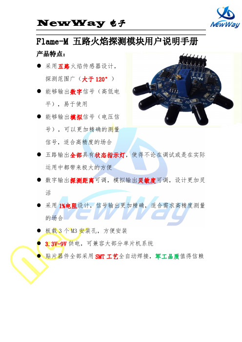
Flame-M 五路火焰探测模块用户说明手册产品特点:●采用五路火焰传感器设计,探测范围广(大于120°)●能够输出数字信号(高低电平),易于使用●能够输出模拟信号(电压信号),可以更加精确的测量信号,适合高精度的场合●五路输出全部具有状态指示灯,使得不论在调试或是在实际运用中都带来极大的方便●数字输出探测距离可调,模拟输出灵敏度可调,设计更加灵活●采用1%电阻设计,信号输出更加精确,适合需求高精度测量的场合●板载3个M3安装孔,方便安装● 3.3V-9V供电,可兼容大部分单片机系统●贴片器件全部采用SMT工艺全自动焊接,军工品质值得信赖模块原理本产品能够探测火焰发出的波段范围分别为700—1100 nm的短波近红外线(SW-NIR),通过电信号(电压信号)进行输出。
•模块接口说明信号输出口(从上到下):A1(第一个输出口既是,模块上标注为A2了): 第一路火焰传感器模拟信号输出口,随着火焰强度的增加输出电压升高D1(第一个输出口既是,模块上标注为D2了): 第一路火焰传感器数字信号输出口,高电平表示有火焰(指示灯亮),低电平标识无火焰(指示灯灭)A2: 第二路火焰传感器模拟信号输出口,随着火焰强度的增加输出电压升高D2: 第二路火焰传感器数字信号输出口,高电平表示有火焰(指示灯亮),低电平标识无火焰(指示灯灭)A3: 第三路火焰传感器模拟信号输出口,随着火焰强度的增加输出电压升高D3: 第三路火焰传感器数字信号输出口,高电平表示有火焰(指示灯亮),低电平标识无火焰(指示灯灭)A4: 第四路火焰传感器模拟信号输出口,随着火焰强度的增加输出电压升高D4: 第四路火焰传感器数字信号输出口,高电平表示有火焰(指示灯亮),低电平标识无火焰(指示灯灭)A5: 第五路火焰传感器模拟信号输出口,随着火焰强度的增加输出电压升高D5: 第五路火焰传感器数字信号输出口,高电平表示有火焰(指示灯亮),低电平标识无火焰(指示灯灭)电源接口(横排相连,随便接一个即可):VCC:模块电源正极输入口,输入范围3.3V-9V(相对于GND)GND:模块电源负极输入口距离调节旋钮:对于模拟输出:逆时针旋转(想标识增高的地方旋转),灵敏度增加,既只需要很小的输入就能得到很高的电压输出对于数字输出:逆时针旋转(想标识增高的地方旋转),探测增加,很远的距离就可以得到数字输出距离调节旋钮注意事项:5路共用一个调节旋钮技术参数探测波长:700—1100 nm探测距离:大于1.5m供电电压:3V-9V注意事项阳光对其有一定影响,使用时避开阳光使用,为减少干扰,可以在传感器端加热缩管。
火焰传感器

用途:
各种火焰,火源探测,2路继电器输出,可接220V大电流设备电器
模块特色:
1、12V电源输入专供继电器使用,板载78L05稳压三极管,提供传感器比较器用,使产品更稳定可靠;
2、可以检测火焰或者波长在760纳米~1100纳米范围内的光源,打火机测试火焰距离为80cm,对火焰越大,测试距离越远
3、探测角度60度左右,对火焰光谱特别灵敏
4、灵敏度可调(图中蓝色数字电位器调节)
5、比较器输出直接触发继电器
6、外形尺寸为:60x43mm,厚19mm,设有固定螺栓孔,方便安装
6、2路输出带蓝色接线座,接线方便
电气参数:
供电电压:12VDC
电流:大于200mA
负载:250V 10A 交流或30V 10A直流
模块使用说明:
1、火焰传感器对火焰最敏感,对太阳光也是有反应的,一般用做火焰报警等用途。
2、通过调节电位器,可以设定传感器感应火焰的强度,当火焰超过设定阈值时,继电器吸合,公共端与常开端接通,,当火焰低于设定阈值时,继电器断开,公共端与常闭端接通;
3、公共端,常开,常闭三个端口相当于一个双控开关,继电器线圈有电时,公共
端与常开端导通,无电时,公共端与常闭端导通;、
4、传感器与火焰要保持一定距离,以免高温损坏传感器,对打火机测试火焰距离为80cm,对火焰越大,测试距离越远。
HMS-FD-3IR点型红外火焰探测器用户使用手册说明书

HMS-FD-3IRRev A.1HMS-FD-3IR点型红外火焰探测器用户使用手册关于本手册 本手册将介绍如何安装和使用HMS-FD-3IR点型红外火焰探测器。
负责安装、调试、操作或维护这些产品的所有人员都应阅读本手册。
在安装该产品之前,请先阅读并完全理解本手册。
尽管我们已尽力确保本文档的准确性,但是Honeywell对任何错误或遗漏或其结果概不负责。
若能将本文档内容中的任何错误或遗漏告知我们,我们将不胜感激。
对于本文档中未包含的信息,或如需提供注释/修正,请通过背页上给出的详细联系信息联系Honeywell。
Honeywell保留更改或修订本文档中提供的信息的权利,恕不另行通知且无义务将此修订或更改通知任何人或组织。
HMS-FD-3IR用户使用手册目 录关于本手册 (2)目录 (3)一、注意事项 (4)防爆注意事项 (4)二、产品概述 (5)1、产品特点 (5)2、主要用途及适用范围 (5)三、结构特征 (6)四、技术参数 (7)1、技术参数表 (7)2、防爆要点 (7)五、接线方式 (8)1、探测器接线端子示意图 (8)2、探测器接线定义表 (8)3、灵敏度设定 (9)4、输出的自锁/非自锁设置 (9)六、探测器安装方式 (10)1、保护区域 (10)2、安装原则 (10)3、安装方式 (10)七、产品组件 (12)八、生产者 (12)一、注意事项感谢您使用HMS-FD-3IR系列火焰探测器(以下简称探测器),设备安装、操作和维护之前务必仔细阅读本说明书。
1.特别留意警告和注意事项。
2.安装过程及操作必须严格遵守国家相关标准要求。
3.探测器内部的任何操作都必须经由培训过的人员执行。
4.切勿擅自或任意拆卸传感器。
5.不得将传感器置于超建议范围的温度下。
6.不得将传感器置于有机溶剂或可燃性液体中。
7.传感器使用期限达到时,应从环保的角度,依照地方废物管理以及环境法规的要求进行安全处理。
或退回我公司进行集中的无害化处理。
火焰检测传感器模块使用说明
//设置显示位置为第一行第 17 列
龙戈电子:
诚信、热情、专业
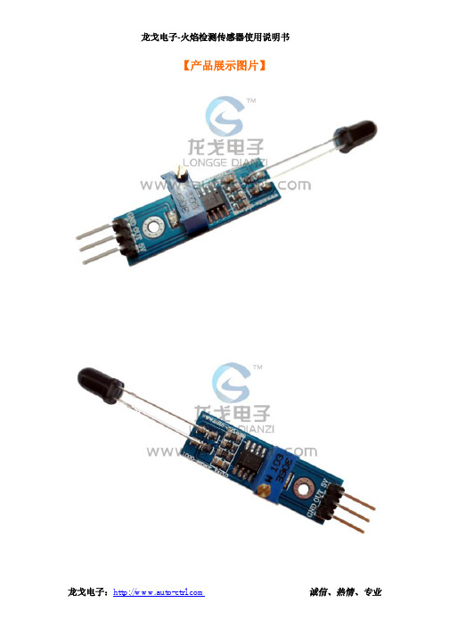
龙戈电子-火焰检测传感器使用说明书
delay(300);
i = 0;
while(dis5[i] != '\0')
{
lcd_pos(0x4f+i);
//显示字符"
"
lcd_wdat(dis5[i]);
{
// delay(300);
if(warning == 1)
{
i=0;
while(Safe[ i ] != '\0')
{
lcd_pos(0x43+i);
lcd_wdat(Safe[i]);
i++;
delay(30);
}
beep = 1;
// delay(300);
}
}
}
break;
default:
诚信、热情、专业
龙戈电子-火焰检测传感器使用说明书
delay(1); lcd_wcmd(0x01); delay(1); }
//清除 LCD 的显示内容
main()
{
BYTE i;
int j=0;
lcd_init();
// 初始化 LCD
delay(10);
lcd_wcmd(0x06);
//向右移动光标
//设TE dat) { while(lcd_bz()); LCD_RS = 1; LCD_RW = 0; LCD_EP = 0; P0 = dat; _nop_(); _nop_(); _nop_(); _nop_(); LCD_EP = 1; _nop_(); _nop_(); _nop_(); _nop_(); LCD_EP = 0; }
火闸传感器使用指南说明书

TM WST-600 AUDIO DETECTOR US Patent # 9,087,447Installation Manual & Users GuideSPECIFICATIONSFrequency: 433.92MHz Operating Temperature: 32°-120°F (0°-49°C) Battery: One3Vdc lithium CR123A (1550 mAh) Operating Humidity: 5-95% RH non condensingBattery life: 4 years Compatible with 433MHz DSC Security SystemsDetection distance: 6 in max Supervisory signal interval: 64 min(approx.)OPERA TIONThe FireFighter™ sensor is designed to listen to any smoke, carbon or combo detector. Once confirmed as an alarm, it will transmit a signal to the alarm control panel which if connected to a central monitoring station, will dispatch the fire department.ENROLLINGFollow the instructions provided by your control panel, or wireless receiver manual. The 6 digit serial number is printed on back of each device. To monitor smoke alarms, when prompted by the panel, enter the 6 digit serial number as printed on the device. Use either zone type 88 ( Standard 24hour fire) or type 87 (Delayed 24 hour fire). Remember to set the wireless bit (bit 8) for that zone attribute.To monitor a CO detector, take the printed serial number and replace the first digit with an 8. For example if the number printed is 436A48, you woulduse 836A48 as the serial number for the CO portion. Use zone type 81 (24 hour Carbon Monoxide).MOUNTING (see IMAGE: 2)Included with this device is a mounting bracket, hardware and double sided tape. To ensure proper operation ensure the side of the device with the small holes is directly facing the sounder holes on the smoke detector. Secure the mounting bracket to the wall or ceiling using thetwo mounting screws and double sided tape provided, then secure the audio detector to the mounting bracket using the small screw provided. The FireFighter™ must be mounting within 6 inches of the detector for optimal operation.***** It is possible that the sensor can hear other smoke detectors in close proximity so it is important to choose and to install the sensor close to a detector that is relatively isolated from other detector. It that is not possible, the sensor will still function it will however take longer to register and transmit to the panel. Smoke detectors to avoid are typically ones mounted in hallways outside of bedrooms that will also have additional smoke detectors.WARNING: Non-interconnected smoke detectors require an audio detector by each smoke detector sounder.This equipment should be installed in accordance with Chapter 2 of the National Fire Alarm Code, ANSI/NFPA 72, (National Fire Protection Association, Batterymarch Park, Quincy, MA 02269). Printed information describing proper installation, operation, testing, maintenance, evacuation planning, and repair service is to be provided with this equipment. Warning: Owner’s instruction notice: ’Not to b e removed by anyone except occupant’.TESTING (see IMAGE: 1)To test the RF transmission from the mounted position you can either generate a tamper by removing the cover or press the learn button located next to the tamper switch. Press and release ONCE to send a Smoke signal or press and HOLD for 2 seconds to send a Carbon signal.Within the first hour of power up the sensor is in a test mode. This mode is designed to work with the test button of the smoke detector so that only 1 or 2 temporal patterns is required to trigger the sensor. After the 1 hour has elapsed the sensor will require at least 3 rounds of either temporal 3 (smoke) or temporal 4 (CO) before it will send a transmission to the control panel. . Ensure the FireFighter™ cove r is on and that you wear hearing protection when doing the audio testing. Then simply press and hold the smoke detector test button.If 24 Hr, delay fire zone type is used the alarm must be active for 30 second before the panel will transmit to the Central Station.NOTE: This system must be checked by a qualified technician at least once every three (3) years. Please test the unit once per week to ensure proper functionality.Legacy Smoke DetectorsAll Smoke detector should be replaced after 10 year. If you encounter a smoke detector that does not support Temporal 3 pattern, that smoke should be replaced as per the manufacturer recommendation.If replacement is not an option the FireFighter can be program to detect non-temporal detectors.** In this mode, the sensor must not be located near any other audible device, like the security keypad or sounder. Those can be misconstrued as a valid smoke alarm. To enter this mode press and hold the tamper button while inserting the battery. Release the tamper switch and note the LEDONE flash: Only a Temporal 3 and 4 signal will trigger an alarm (Default)TWO flashes: Generic listening mode. (Will trigger after 30 seconds of continuous sound)You can verify the mode the device is in by simply removing the battery and replacing it. The LED will flash once or twice depending on the mode it is in. Repeat the steps above to change the mode as required.REPLACING THE BATTERYWhen the battery is low a signal will be sent to the control panel. To replace the battery:1. Remove the top cover to reveal the battery. This will send a tamper signal to the control panel.2. Replace with a Panasonic CR123A battery ensuring the + side of the battery faces as indicated on the device.3. Re-attach the cover, you should hear a click when the cover engages properly.WARNING: While the audio detector monitors its own battery, it does not monitor the battery in the smoke detectors. Batteries should be changed as per the original smoke detector manufacturer’s instructions. Always test the audio detector and smoke alarms after battery installation to confirm proper operationFCC COMPLIANCE STATEMENTThis equipment has been tested and found to comply with the limits for Class B digital devices, pursuant to Part 15 of the FCC Rules. These limits are designed to provide reasonable protection against harmful interference in a residential installation. This equipment generates uses and can radiate radio frequency energy and, if not installed and used in accordance with the instruction manual, may cause harmful interference to radio communications. However, there is no guarantee that interference will not occur in a particular installation. If this equipment does cause harmful interference to radio or television reception, which can be determined by turning the equipment off and on, the user is encouraged to try to correct the interference by one or more of the following measures:• Re-orient or relocate the receiving antenna• Increase the separation between the equipment and receiver• Connect the equipment to an outlet on a different circuit from the receiver• Consult the dealer or an experienced radio/TV contractor for help.WARNING: Changes or modifications not expressly approved by Ecolink Intelligent Technology Inc. could void the user’s authority to operate the equipment.This device complies with Industry Canada license-exempt RSS standard(s). Operation is subject to the following two conditions: (1) this device may not cause interference, and (2) this device must accept any interference, including interference that may cause undesired operation of the device.FCC ID: XQC-WST600 IC: 9863B-WST600WARRANTYEcolink Intelligent Technology Inc. warrants that for a period of 2 years from the date of purchase that this product is free from defects in material and workmanship. This warranty does not apply to damage caused by shipping or handling, or damage caused by accident, abuse, misuse, misapplication, ordinary wear, impropermaintenance, failure to follow instructions or as a result of any unauthorized modifications. If there is a defect in materials and workmanship under normal use within the warranty period Ecolink Intelligent Technology Inc. shall, at its option, repair or replace the defective equipment upon return of the equipment to the original point of purchase. The foregoing warranty shall apply only to the original buyer, and is and shall be in lieu of any and all other warranties, whether expressed or implied and of all other obligations or liabilities on the part of Ecolink Intelligent Technology Inc. neither assumes responsibility for, nor authorizes any otherperson purporting to act on its behalf to modify or to change this warranty, nor to assume for it any other warranty or liability concerning this product. The maximum liability for Ecolink Intelligent Technology Inc. under all circumstances for any warranty issue shall be limited to a replacement of the defective product. It is recommended that the customer check their equipment on a regular basis for proper operation.THE LIABILITY OF ECOLINK INTELLIGENT TECHNOLOGY INC. , OR ANY OF ITS PARENT OR SUBSIDIARY CORPORATIONS ARISING FROM THE SALE OF THIS SMOKEALARM DETECTOR OR UNDER THE TERMS OF THIS LIMITED WARRANTY SHALL NOT IN ANY CASE EXCEED THE COST OF REPLACEMENT OF A SMOKE ALARM DETECTOR AND, IN NO CASE, SHALL ECOLINK INTELLIGENT TECHNOLOGY INC. , OR ANY OF ITS PARENT OR SUBSIDIARY CORPORATIONS BE LIABLE FOR CONSEQUENTIAL LOSSES OR DAMAGES RESULTING FROM THE FAILURE OF THE SMOKE ALARM DETECTOR OR FOR BREACH OF THIS OR ANY OTHER WARRANTY, EXPRESS OR IMPLIED, EVEN IF THE LOSS OR DAMAGE IS CAUSED BY THE COMPANY’S NEGLIGENCE OR FAULT.The Firefight er™ detector does not detect the presence of smoke, heat, or fire directly. It relies solely on the presence of an audio alar m signal generated by anexisting smoke or fire detector in proximity to the Firefighter™ detector to make such a determination. The Firefighter™ detector must be used with smoke detectors certified according to UL Standards, and in strict accordance with the installation and operation instructions provided with such detectors. It is the owner’sresponsibility to ensure that smoke or fire detectors used in conjunction with the Firefighter™ detector are maintained and tested on a regular basis in accordance with the manufacturer’s instructions. Ecolink Intelligent Technology Inc. expressly disclaims any responsibility for the failure o f the Firefighter™ detector to detect the presence of smoke or fire due to the failure of any smoke or fire detector used in conjunction with the Firefighter™ dete ctor to operate properly due to any condition, including improper installation, operation, maintenance or testing of such smoke or fire detector .LEARN BUTTON TAMPER SWITCH2055 Corte Del NogalCarlsbad, California 92011 1-855-632-6546PN WST-600 R1.00REV DATE: 12/07/16IMAGE 1: ENROLLING / TEST / TAMPER BUTTONIMAGE 2: INSTALLATION DISTANCE 6” MAX。
火焰传感器的使用流程
火焰传感器的使用流程1. 概述火焰传感器是一种用于检测火焰的设备,可以广泛应用于火灾预警、工业生产等领域。
本文将介绍火焰传感器的使用流程,包括安装、连接和测试等步骤,帮助用户正确使用火焰传感器。
2. 安装2.1 确定安装位置在安装火焰传感器之前,需要选择一个合适的安装位置。
通常情况下,应该选择离潜在火源较近、易于观察的位置进行安装。
2.2 固定传感器使用螺丝将传感器固定在所选的安装位置上。
确保传感器安装牢固,不容易被误移或摇动。
3. 连接3.1 连接电源将火焰传感器的电源线连接到适配器或电源控制器上。
确保电源接线正确,以防止短路或电源异常。
3.2 连接信号线将火焰传感器的信号线连接到控制器或数据采集设备上。
确保信号线连接牢固,以免因连接不良造成数据传输错误。
3.3 接地处理根据需要,对火焰传感器进行接地处理,以确保传感器的正常运行和安全性。
4. 测试4.1 确保供电正常在进行传感器测试之前,需要确保传感器已经正常供电。
检查电源线是否连接正确,电源是否正常。
4.2 确认信号接收使用控制器或数据采集设备确认是否能够正常接收到火焰传感器发送的信号。
可以使用示波器或软件进行检测。
4.3 模拟火焰信号可以使用火焰模拟器或者其他方式产生火焰信号,测试火焰传感器对火焰的检测能力。
确保传感器能够准确地检测到火焰并发出相应的信号。
5. 使用注意事项5.1 防尘防水保持火焰传感器干燥、清洁,避免灰尘和水分进入传感器内部,以免影响传感器的正常工作。
5.2 避免干扰保持火焰传感器远离其他可能产生干扰的设备,如高频电磁辐射设备。
可采取屏蔽或隔离措施,以保证传感器的稳定性和准确性。
5.3 定期检测定期检测火焰传感器的工作状态。
可以通过模拟火焰信号或者其他方式进行测试,确保传感器能够正常工作。
6. 故障排除6.1 无信号输出如果火焰传感器无信号输出,可以检查供电是否正常、信号线是否连接好等。
若仍不能解决问题,可能需要更换传感器。
火焰光度计使用说明书

火焰光度计使用说明书使用准备:1. 确保火焰光度计已经连接电源,并处于正常工作状态。
2. 确保火焰光度计与待测试的火焰源之间没有任何障碍物,以避免干扰光线的传输。
测量操作:1. 打开火焰光度计,并等待其进行自检程序,确保仪器正常工作。
2. 将待测试的火焰源放置在火焰光度计的测量范围内,并确保火焰源与仪器的光线传感器保持一定的距离。
距离应根据具体情况进行调整,以确保测量结果的准确性。
3. 按下火焰光度计上的测量按钮,开始测量火焰源的光度。
4. 仪器将会自动记录测量结果,并显示在屏幕上。
同时,还可以将测量结果保存在内存中供之后的分析使用。
5. 对于不同的火焰源,可以选择不同的测量模式,以获得更准确的测量结果。
请参考火焰光度计的用户手册,了解各个测量模式的具体用途和使用方法。
数据分析与处理:1. 火焰光度计可以提供一些基本的数据分析和处理功能,以帮助用户更好地理解测量结果。
用户可以通过仪器上的按键或触摸屏来访问这些功能。
2. 数据分析功能包括峰值检测、光强曲线绘制等。
用户可以根据需要选择相应的功能,并根据屏幕上的指引进行操作。
3. 火焰光度计还可以将测量结果导出至计算机,以便进行更复杂的数据处理和分析。
用户需要连接计算机与仪器,并按照软件指引来完成数据的导出操作。
注意事项:1. 使用过程中,请勿将火焰光度计暴露在过高的温度下,以免损坏仪器。
2. 在测量前,请确保火焰源已经稳定燃烧,并尽量保持其不受外界干扰。
3. 在进行测量时,应尽量避免其他光源的干扰,以确保测量结果的准确性。
4. 定期清洁仪器的光线传感器和光学系统,以保持仪器的灵敏度和测量精度。
故障排除:1. 若火焰光度计无法正常启动或显示异常,请先检查电源连接是否正确,并尝试重新启动仪器。
2. 若上述方法无效,请参考用户手册中的故障排除部分,按照指引进行故障的排查与处理。
封存与保养:1. 当您不再需要使用火焰光度计时,请将其关机,并拔掉电源线。
2. 将仪器放置在干燥、通风的地方,并保持仪器表面的清洁。
- 1、下载文档前请自行甄别文档内容的完整性,平台不提供额外的编辑、内容补充、找答案等附加服务。
- 2、"仅部分预览"的文档,不可在线预览部分如存在完整性等问题,可反馈申请退款(可完整预览的文档不适用该条件!)。
- 3、如文档侵犯您的权益,请联系客服反馈,我们会尽快为您处理(人工客服工作时间:9:00-18:30)。
{
// delay(300);
if(warning == 1)
{
i=0;
while(Safe[ i ] != '\0')
{
lcd_pos(0x43+i);
lcd_wdat(Safe[i]);
i++;
delay(30);
}
beep = 1;
// delay(300);
}
}
}
break;
default:
i++;
}
delay(300);
for(j=0;j<16;j++)
{
lcd_wcmd(0x18);
delay(800);
}
display=2;
}
break;
//设置显示位置为第一行第 17 列
//向左移动 16 格 //字符同时左移一格 //控制移动时间
case 2: {
flash(); delay(1000); lcd_wcmd(0x01); delay(20); display = 3; lcd_wcmd(0x06);
lcd_wdat(Fire[i]);
i++;
delay(30);
}
for(i=0;i<3;i++)
{
beep = 0;
delay(200);
beep = 1;
delay(200);
}
}
}
//////////////////////////////////////////
if(warning == 1)
int i,j,display=0,t02s; sbit LCD_RS = P2^5; sbit LCD_RW = P2^6; sbit LCD_EP = P2^7; sbit warning = P3^2; sbit beep = P3^4; //////////////显示数组 BYTE code dis1[] = {" WELCOME TO "};
********************************************************************/
/********************************************************************
说明:1、 当着火时,传感器输出低电平 1602 液晶显示 Fire 蜂鸣器响
//控制两屏转换时间
display = 1;
lcd_wcmd(0x06);
//向右移动光标
}
break;
case 1:
{
delay(300);
i = 0;
while(dis1[i] != '\0')
{
//显示字符"
"
lcd_pos(0x8A+i); lcd_wdat(dis1[i]); i++; }
诚信、热情、专业
龙戈电子-火焰检测传感器使用说明书
P0 = cmd; _nop_(); _nop_(); _nop_(); _nop_(); LCD_EP = 1; _nop_(); _nop_(); _nop_(); _nop_(); LCD_EP = 0; }
void lcd_pos(BYTE pos) { lcd_wcmd(pos | 0x80); }
诚信、热情、专业
龙戈电子-火焰检测传感器使用说明书
delay(1); lcd_wcmd(0x01); delay(1); }
//清除 LCD 的显示内容
main()
{
BYTE i;
int j=0;
lcd_init();
// 初始化 LCD
delay(10);
lcd_wcmd(0x06);
//向右移动光标
//清除 LCD 的显示内容 //控制两屏转换时间
//向右移动光标
} break; case 3: {
i=0; while(dis3[ i ] != '\0') {
lcd_pos(0x80+i); lcd_wdat(dis3[i]); i++; delay(30); } display=4; } break; case 4:
//设定显示位置
void lcd_wdat(BYTE dat) { while(lcd_bz()); LCD_RS = 1; LCD_RW = 0; LCD_EP = 0; P0 = dat; _nop_(); _nop_(); _nop_(); _nop_(); LCD_EP = 1; _nop_(); _nop_(); _nop_(); _nop_(); LCD_EP = 0; }
适用场合:物联网产品开发、电子竞赛、毕业设计、传感器 教学等。
【STC12C5A60S2 单片机连接测试程序】
/******************************************************************** 龙戈电子
实现功能:最小系统版配套测试程序 使用芯片:STC12C5A60S2 晶振:11.0592MHZ 波特率:9600 编译环境:Keil 作者:LOGO 网站: 【声明】此程序仅用于学习与参考,引用请注明版权和作者信息!
//写入字符显示数据到 LCD
void lcd_init() { lcd_wcmd(0x38); delay(1); lcd_wcmd(0x0c); delay(1); lcd_wcmd(0x06);
//LCD 初始化设定 //16*2 显示,5*7 点阵,8 位数据
//显示开,关光标
//移动光标
龙戈电子:
6、电路板输出 OUT 标识为开关量,可直接接单片机 IO 口, 无火焰时输出高电平指示灯灭,有火焰时输出低电平,指示 灯亮,响应时间<2µs;
7、用于火焰检测,可检测 760 纳米~1100 纳米范围内的热源, 火焰探测角度为 60°范围;
操作说明请参看我们的优酷视频:/龙戈电子
while(1)
{
switch(display)
{
case 0:
{
i=0;
while(dis2[ i ] != '\0')
{
lcd_pos(0x80+i);
lcd_wdat(dis2[i]);
i++;
delay(300);
}
flash();
lcd_wcmd(0x01);
//清除 LCD 的显示内容
delay(20);
诚信、热情、专业
void flash(); void delay(int ms) {
while(ms--) {
for(i = 0; i< 250; i++) { _nop_(); _nop_(); _nop_(); _nop_(); } } }
// 延时子程序
BOOL lcd_bz() { BOOL result; LCD_RS = 0; LCD_RW = 1; LCD_EP = 1; _nop_(); _nop_(); _nop_(); _nop_(); result = (BOOL)(P0 & 0x80); LCD_EP = 0; return result; }
龙戈电子:
诚信、热情、专业
龙戈电子-火焰检测传感器使用说明书
BYTE code dis2[] = {""}; BYTE code dis3[] = {" TEST...... "}; BYTE code dis5[] = {""}; BYTE code Fire[] = {"Fire "}; BYTE code Safe[] = {"Safe "};
for(i=0;i<12;i++) { delay(200);
} lcd_wcmd(0x08);
for(i=0;i<12;i++) { delay(200); } lcd_wcmd(0x0c);
for(i=0;i<12;i++) { delay(200); } }
//控制停留时间 //关闭显示
龙戈电子:
2、 传感器常态时输出高电平
1602 液晶显示 Safe
********************************************************************/
#include <reg51.h>
#include <intrins.h>
typedef unsigned char BYTE; typedef bit BOOL;
1、具有信号输出指示灯;
2、单路信号输出,输出信号可以直接接单片机 IO 口;
3、OUT 口输出高低电平信号,高电平为 3.8V,低电平为 0V;
4、灵敏度可调(精调),调节火焰检测范围;
5、带固定安装孔,方便安装调试;
龙戈电子:
诚信、热情、专业
龙戈电子-火焰检测传感器使用说明书_wcmd(BYTE cmd) { while(lcd_bz()); LCD_RS = 0; LCD_RW = 0; LCD_EP = 0; _nop_(); _nop_();
// 写入指令数据到 LCD
龙戈电子:
龙戈电子:
诚信、热情、专业
龙戈电子-火焰检测传感器使用说明书
break; }
} } void flash() {