PAC50气动压力开关操作手册(中文版)
PAC50气动压力开关操作手册(中文版)

PAC50压力传感器: 易于集成控制
• 可选含IO-Link接口的型号, 使其能够通过连接的控制器快速、 精确地设置PAC50压力传感器的参数 • 减少停机时间, 当需要改变和更换产品时, 可通过总线更改或拷贝参数, 使用更方便。
PAC50压力传感器: 可靠且坚固耐用
• 采用防尘和防水外壳设计 (IP 65和IP 67外壳防护等级) , 是各种工业应用, 甚至是严苛 环境应用的理想之选
8016724/2014-10-23 如有更改, 恕不另行通知
PAC50 | SICK
5
PAC50 压力传感器
转变显示压力颜色
产品描述
为了更好地监测气压, 西克生产的PAC50 电子压力开关提供了一系列优势, 包括: 采用双色显示屏让您从远处就能判断压 力是否在设定范围内; 三个大的功能键 和直观的菜单导航使PAC50压力传感器 的操作更简单。 是什么让PAC50压力传感 器如此卓尔不群? 它在一个设备上就能 提供多达两个数字开关输出和一个可选 的模拟输出, 输出信号可根据控制系统的 要求轻松进行调节。 此外, 它还可以选配 IO-Link 接口, 在改变参数或更换传感器 时, 控制器或PLC能够快速且精确地将设 备参数拷贝至传感器, 从而显著降低故障 停机时间。 PAC50压力传感器的IP 65/IP 67级防水外壳使其成为各种工业应用的 理想之选。
电气安全
防护等级: III级 过压保护: 32 V DC 短路保护: QA、 Q1、 Q2与M及L+之间有短路保护 极性反接保护: L+和M之间有极性反接保护 EMC指令: 2004/108/EC, EN 61326-2-3 约40 g 防护等级为IP 65 / IP 67, 符合标准IEC 60529 (注意采用合适的连接方式) l l
609可调设定点气体压差开关使用说明书
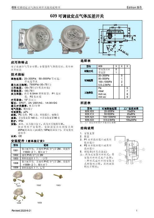
609可调设定点气体压差开关应用和特点用于监测空气等非可燃、非腐蚀性气体的过压、真空和压差状态技术指标量程范围:20~300Pa ,50~500Pa 等可选,详见选型表最大压力限制:7500Pa(-30~75℃)工作温度:-30~75℃(介质及环境)存储温度:-30~75℃压力连接:内径6.0mm 塑料软管,P1高压端,P2低压端开关寿命:106次以上输出:SPDT ,2A/250VAC ,1A/30VDC 最大开关频率:6次/分钟电气连接:螺丝端子可重复性:±2%材质:PC 壳体,PC 上盖,硅胶膜片,银触点重量:含安装支架140克,不含安装支架90克防护:IP54安装:垂直,压力接口向下。
此为开关校准位置。
如必须水平安装时,实际设定点比刻度点加20Pa(封盖向上)或减约10Pa(封盖向下),详见使用说明书认证:CE安装配件(需单独订货)型号说明1001独立配件包,含透明PVC 导气管2M ,连接件(1003)2个,螺丝4个1002透明PVC 导气管2M 1003塑料连接件1个,一字型1008独立配件包,含透明PVC 导气管2M ,连接件(1009)2个,螺丝4个1009塑料连接件1个,L 型选型表型号609X XX封装方式带安装耳环0带支架1可调范围20~300Pa 050~500Pa 1100~1000Pa 20.5~2.5kPa 3工程单位Pa 0mbar 7inch wc 8mm wc9回差表型号可调量程范围工厂设定回差609.X0X 20-300Pa 10±5Pa 609.X1X 50-500Pa 20±8Pa 609.X2X 100-1000Pa 50±15Pa 609.X3X0.5-2.5kPa100±30Pa注:工厂设定回差客户不能自行调整结构说明1.安装支架2.膜盒3.P1压差高压端口或真空低压端口4.P2压差低压端口或真空高压端口5.刻度盘(开关点设定)注:此为无安装耳环形式。
压力开关说明7页

操作手册压力继电器(压力开关)YSJ-340系列一、概述YSJ-340系列压力继电器是一种超小型压力控制仪表,用于液压、气动系统的压力显示与控制,可替代德国贺德克HYDAC(贺德克)EDS300系列压力继电器。
该仪表采用了高精度压力传感器,电路部分以高性能单片机微处理器为核心,具有3位LED数字显示及轻触开关输入的人机界面、具有开关量(报警)输出及4~20mA模拟输出,是在机械继电器无法胜任的条件(如压力剧烈波动、强环境振动、高精度高速度控制、小体积等)下可靠工作的理想选择。
二、性能指标◇测量范围:0~1.6—0~60MPa◇电源电压:16~36VDC◇输出信号:(RL≤250Ω)◇接口螺纹:G1/4◇环境条件:环境温度:-20℃~60℃介质温度::-20℃~80℃存储温度:-40℃~125℃相对湿度:0~80%耐冲击:≤50g/ms耐振动:≤10g/(0~500HZ)◇输出信号精度:1.0◇过载压力:1.5%倍满量程压力◇最大功耗:≤3W触点容量:24VDC/1.2A(MAX)三、功能根据不同型号,装置可提供下列功能◇三位显示当前压力(正常工作)◇按压力、预设开关点输出开关量◇输出模拟量◇基本设定菜单◇提供四种不同输出模式:◇YSJ341带1路开关量输出(负载最大电流1.2A,无模拟量输出)◇YSJ342带2路开关量输出(负载最大电流1.2A,无模拟量输出)◇YSJ343带1路开关量输出(负载最大电流1.2A)和1路模拟量输出(4~20mA)◇YSJ344带2路开关量输出(负载最大电流1.2A)和1路模拟量输出(4~20mA)四、安装YSJ340可以通过压力管接头(DIN3852内螺纹G1/4),直接装在液压集成快上。
电气连接必须由国家认定合格的电工操作(参考中国电工国家标准规范)。
压力继电器的外壳必须同时良好的接地。
如安装在液压块里,块体通过液压系统接地时有保证的。
若用微型软管安装,客体必须单独接地。
AVENTICS 压力开关Series PM1 用户操作手册说明书

Pressure Switches, Series PM1- Operating pressure -0,9 ... 0 -0,9 ... 3 0,2 ... 16 bar- Mechanical- Spring-loaded bellow, adjustable- Electr. connection Plug EN 175301-803, form A- Compressed air connection Internal thread G 1/4 Flange with O-ring Ø 5x1,5Type MechanicalFunction change-over contact (mechanical)Mounting orientation AnyWorking pressure min./max.See table belowAmbient temperature min./max.-20 ... 80 °CMedium temperature min./max.-10 ... 80 °CMedium Compressed air, Hydraulic oilMeasurement Relative pressureSwitching element microswitch (input/output)Protection against overpressure80 barMax. switching frequency1,5 HzShock resistance max.15 gVibration resistance10 g (60 - 500 Hz)Repeatability (% of full scale value)± 1 %Switching point adjustableHysteresis max. switching pressure differenceDC operating voltage min./max.12 ... 30 V DCOperational voltage AC min./max.12 ... 250 V ACMounting types via through holesProtection class IP65Electr. connection Plug EN 175301-803, form AWeight0,16 kg1) Min. switching pressure range 0.2 bar falling/0.5 bar rising1) Valve plug connector2) Adjustment screw, self-holding1) Valve plug connector2) Adjustment screw, self-holding3) cylinder screw M5x30 (included in scope of delivery)4) O-ring Ø5x1,5 (included)A) p1 (-), min.B) p1 (-), max.p1 (+) = upper switching pressure with increasing pressure p1 (-) = lower switching pressure with decreasing pressureA) p1 (-), min.B) p1 (-), max.p1 (+) = upper switching pressure with increasing pressure p1 (-) = lower switching pressure with decreasing pressure Δ p1 = max. operating pressure difference or hysteresis Example:p1 (+) = 8 bar > p1(-) = 7.6 barΔ p1 = 0.4 barreference cycle: 30/min., reference temperature: + 30 °C1) AC2) DCreference cycle: 30/min., reference temperature: + 30 °C1) AC2) DC3) cos ≈ 0,7°4) L/R ≈ 10 msAllocation+UB break contact NO (make contact)GNDYour local contact:/contactus/EmersonAutomationSolutions/company/Emerson-Automation-SolutionsAn example configuration is depicted on the title page. The delivered product may thus vary from that in the illustration. Subject to change. This Document, as well as the data, specifications and other information set forth in it, are the exclusive property of AVENTICS GmbH. It may not be reproduced or given to third parties without its consent. Only use the AVENTICS products shown in industrial applications. Read the product documentation completely and carefully before using the product. Observe the applicable regulations and laws of the respective country. When integrating the product into applications, note the system manufacturer's specifications for safe use of the product. The data specified only serve to describe the product. No statements concerning a certain condition or suitability for a certain application can be derived from our information.The information given does not release the user from the obligation of own judgement and verification. It must be remembered that the products aresubject to a natural process of wear and aging.of the Emerson family of companies. All other marks are the property of their respective owners. © 2020 Emerson Electric Co.All rights reserved.2020-12。
空压机操作说明书-标准版
不能允许: —压缩机压力超过铭牌所示的压力值。 —改变和拆除安全装置和保护罩。 —除去空气压缩机上的有关安全和警示的标记或者上漆涂抹之。 —让非专业人员或者未经培训人员上机操作。
5
运输损伤
Boge 公司对机器的运输损伤不承担责任。请在得到供货之后立即检查机器, 向运输公司提出机器损伤的申述,即使外包装未受损坏也一样。为保证申述成 功,我们建议将机器,仪器和包装材料暂时原样保存,以求确认损伤。 其它的不满意见请在货物到达的六天之内向本公司提出。
[°C]
[m3/min] [m3/min] [m3/min]
110
– 0,231
–
110
– 0,338 0,234
110
– 0,428
–
110
– 0,718 0,525
110
– 0,231
–
110
– 0,338 0,234
110
– 0,428
–
110
– 0,718 0,525
Drive motor Rated power Electrical power intake dryer Nominal speed – 50 Hz
55
55
IMB 35
35
35
35
35
35
35
35
F
F
F
F
F
F
F
F
Electrical connection
Netzspannung Kompressor / Trockner 1) [V] 400 400 400 400 400/230 400/230 400/230 400/230
PC50设备使用说明书
最大颗粒尺寸 最大颗粒密度 最大压力露点 最大含油浓度
[μm] 1
[mg/m3] 1
[℃] -40
[mg/m3] 0.1
15
8
+3
5
40
10
+7
25
气源质量达不到上述要求,将对 TOX®-气液增力缸造 成严重损坏;
若因气源质量不达标,而对 TOX®气液增力缸造成损坏 的,TOX 公司将不承担任何责任。
M
G 3/4
d
Φ19 ( 表 3.1 )压缩空气接口尺寸
13
设备使用说明书
3.2 设定与调整
1) 设备准备状态: a. 顺时针转动旋开紧停按钮(见图 1.2 控制面板图示及说明); b. 顺时针转动电源锁开关钥匙使其处于打开位置; c. 启动设备上电,进入工作准备状态。
2) 产品选择: 触摸屏上点击“产品选择”按钮,选择对应产品号,主界面显示程序号。
4
设备使用说明书
目录
符号说明……………………. 2 安全警告……………………. 2 特别声明……………………. 3 版权声明……………………. 3
5 维护及保养………………… 18 5.1 日常维护…………………… 19 5.2 模具更换…………………… 21 5.3 常见故障及其处理………… 22 5.4 设备易损件及备件明细表… 23
11
设备使用说明书
2.2.2 气源质量标准
(表 2.2.2.1 TOX®冲压连接设备气源质量标准)
固态颗粒
分类
[μm]
5
40
结露点
分类最大含油量
分类 2
[mg/m3] 0.1
分类
2 4 5
(表 2.2.2.2 DIN ISO 8573-1 标准气源质量分类)
压力开关说明书共7页word资料
DG型气体压力开关使用说明书●请阅读和保持一个安全的地方解释符号●, 1, 2, 3 ... = 功能➔= 用法说明所有工作必须在阅读操作说明后才能进行!警告!不正确的安装、调整、修改、操作或维护可能导致伤害或物质损失。
使用前先阅读说明书。
这个单位必须安装依照本条例的实施。
标准声明We, the manufacturer, hereby declare that the products DG.., marked with product ID No. CE 0085AP0467, comply with the essential requirements of the following Directives:–90/396/EEC in conjunction with EN 1854,–73/23/EEC in conjunction with the relevant standards.The relevant products correspond to the type tested by the notified body 0085. Comprehensive quality assurance is guaranteed by a certifi ed Quality System pursuant to DIN EN ISO 9001 according to annex II, para-graph 3 of Directive 90/396/EEC.Elster Kromschröder GmbH, Osnabrück测试➔电源电压、环境温度和外壳——看类型的标签。
➔最大介质温度:-15 + 80°C。
在系统暴露于更高的热应力、热设备上时压力开关必须安装在上游。
DG..B型➔正压时1号位置为进气DG..U型, DG..H型, DG..N型➔正压时1号或者2号位置为进气,气体为空气、天然气或者烟气(其他位置密封),通风时气体从3号或者4号位置离开。
REXA执行机构培训教程(开关型M-pac中文版)
2.1截止阀是用来在拆卸3单向节流阀、5压力开关、6压力 表、2.1截止阀时将蓄能器中的高压油放回油箱,以防在拆 卸时喷油。平时状态为关。
驱动阀门开关 非连续动作:马达只在需要动作时运转, 节省能源
线路截断阀结构
线路截断阀由执行器(安在阀门上)、控制箱(42号阀室 配有变压器箱)、连接控制箱和执行器的电缆(电机电缆、 控制电缆、反馈电缆)组成。见图片。
旋转油缸结构
接近开关组件结构
阀块结构
线路截断阀执行机构的安装
逻辑预定充压周期次数内无法充到预定压力将 上传报警信号。
操作说明
在充压结束后(油压达到约14.5MPa),可进行远控或转入就地状 态按UP/DOWN按钮进行开关动作
单次开或关动作后应间隔一定时间(约40分钟)来保证蓄能器充 满足够的能量以满足下一次动作需要
为避免误动作对阀门造成的冲击,执行机构采用非自锁式设计。 自动状态下在到达目标位置前撤消开关指令,执行机构将停在指 令撤消时的位置。自动状态下如果在规定时间内未能达到全开位 或全关位,则执行机构将从连续运动转为周期为1秒钟的断续运 动,如果连续动作5次后仍未到达,则停止运动并触发报警
操作说明
系统连接无误后即可通电开机 开机后系统应自动进入远控状态(操作板上的“REMOTE”
指示灯亮) 若按下“R/L”按钮,则REMOTE灯熄灭,转入就地状态,
在就地模式下,执行器将处在离线状态,并不再响应远程指 令信号( ESD信号除外)。
如果开机时蓄能器油压偏低,开机后约等待10~15秒钟后系 统将自动开始充压
潜入式压力卓越型气动阀门用户指南说明书
SpecificationsThese products are intended for use in general purpose compressed air systems only.Operating Pressure Range:psig bar kPa Minimum 30 2.1207Maximum15010.31030NOTE: Solenoid operated valves specified for external pilot or double air pilot operated valves, may have pressures down to vacuum in the main valve. External pilot pressure and air pilot signals must be greater than or equal to that in the main valve, but do not exceed the ranges above.Temperature Range (Ambient):5°F to 120°F (-15°C to 50°C)Voltage Range:+10% to -10% of RatingWiring:Follow all requirements for local and national electrical codes.Wiring instructions and instructions for proper installation are shown on Instruction Form V-390P which is shipped with the original product. Copies of Instruction Form V-390P are avail-able from your local representative.Service InstructionsSubbase Valves:I f valves are removed from their bases during repair, reas-semble valve to base using proper gasket orientation. Reinstall the two socket head cap screws and tighten to 15 in-lbs torque using a 2.5 mm hex wrench. Test the assembly for proper function and leakage before putting into service.Pneumatic DivisionRichland, Michigan 49083!!WARNINGTo avoid unpredictable system behavior that can cause personal injury and property damage:•Disconnect electrical supply (when necessary) before installation,servicing, or conversion.•Disconnect air supply and depressurize all air lines connected to this product before installation, servicing, or conversion.•Operate within the manufacturer’s specified pressure, temperature,and other conditions listed in these instructions.•M edium must be moisture-free if ambient temperature is below freezing.•Service according to procedures listed in these instructions.•Installation, service, and conversion of these products must be performed by knowledgeable personnel who understand how pneumatic products are to be applied.•After installation, servicing, or conversion, air and electrical supplies (when necessary) should be connected and the product tested for proper function and leakage. If audible leakage is present,or the product does not operate properly, do not put into use.•Warnings and specifications on the product should not be covered by paint, etc. If masking is not possible, contact your local representative for replacement labels.WARNINGFAILURE OR IM PROPER SELECTION OR IM PROPER USE OF THE PRODUCTS AND/OR SYSTEM S DESCRIBED HEREIN OR RELATED ITEMS CAN CAUSE DEATH, PERSONAL INJURY AND PROPERTY DAMAGE.This document and other information from Parker Hannifin Corporation,its subsidiaries and authorized distributors provide product and/or system options for further investigation by users having technical expertise. It is important that you analyze all aspects of your application,including consequences of any failure and review the information concerning the product or systems in the current product catalog. Due to the variety of operating conditions and applications for these products or systems, the user, through its own analysis and testing, is solely responsible for making the final selection of the products and systems and assuring that all performance, safety and warning requirements of the application are met.The products described herein, including without limitation, product features, specifications, designs, availability and pricing, are subject to change by Parker Hannifin Corporation and its subsidiaries at any time without notice.EXTRA COPIES OF THESE INSTRUCTIONS ARE AVAILABLE FOR INCLUSION IN EQUIPMENT / MAINTENANCE MANUALS THAT UTILIZE THESE PRODUCTS. CONTACT YOUR LOCAL REPRESENTATIVE.Servicing Valve Body:1.Remove both solenoid coils from the main valve body by removing knurled nuts and washers. Then remove the two cheese head screws which secure the solenoid bases to their solenoid adapters. Remove the two o-rings between solenoid base and adapter. Remove both solenoid adaptors by removing their two mounting screws.NOTE: Keep track of how the parts fit together to aid with re-assembly of valve. Refer to illustration for proper part orien-tation. Clean all parts which are going to be reused (such as seals and gaskets, piston, piston bores, gasket tracks, spools,etc.) with a lint free cloth. Apply fresh grease (provided) to all seals prior to reassembly.2.Remove pistons from solenoid adapters. Then remove lip seals from their pistons.3.Remove the o-rings (item 11) between body and solenoid adapters. Inspect piston bores for nicks, scratches and sur-face imperfections.4.Push spool/seal assembly from body and clean valve bore,taking care not to scratch bore. (If more aggressive cleaning is required, use mineral spirits or equivalent solvent and dry throughly). Inspect body's bore for nicks, scratches, or sur-face imperfections. NOTE: The presence of nicks, scratches and surface imper-fections may reduce service life; thus, future replacement of damaged parts should be planned.5.Lightly grease seals on the spool assembly and install it into valve bore. T ake care to install spool squarely and push slowly to avoid damaging seals or the body’s bore.6.Lightly grease new seals and install between body and sole-noid adapters.7.Apply a light film of grease to operator piston bores and all surfaces of piston seals. Install seals onto pistons with the lips of the seals facing away from the support flange. Install the piston/seal assemblies into their operator bores, taking care to assure that the lips of the seals pass smoothly into the bores.Installation & Service Instructions V-392P“B3B” Series Air Control Valves 1/8" Inline & 1/8" & 1/4" Subbase 3-Position BodyISSUED: September, 1994NPR# 1189Service KitsThe following service kits contain the appropriate seals and parts necessary for ordinary field service.Kit No DescriptionPS2902BP 3-Position all ports blocked body Service Kit PS2903BP 3-Position cylinder to exhaust body Service Kit PS2904BP 3-Position pressure center body Service Kit PS2928G40BP 12VAC Solenoid Kit - 18" Flying Leads PS2928G42BP 24VAC Solenoid Kit - 18" Flying Leads PS2928G53BP 120VAC Solenoid Kit - 18" Flying Leads PS2928P45BP 12VDC Solenoid Kit - 18" Flying Leads PS2928P49BP 24VDC Solenoid Kit - 18" Flying Leads PS2928540BP 12VAC Solenoid Kit - 3-Pin Connector PS2928542BP 24VAC Solenoid Kit - 3-Pin Connector PS2928545BP 12VDC Solenoid Kit - 3-Pin Connector PS2928549BP 24VDC Solenoid Kit - 3-Pin Connector PS2928553BP 120VAC Solenoid Kit - 3-Pin ConnectorPS2944P Solenoid Base/Armature with Manual Override PS2945P Solenoid Base/Armature without ManualOverrideOther Service Instruction Sheets:V-390P Valve Installation & Service Instruction Sheet V-393P Solenoid & Pilot Body Service Instruction Sheet V-394P Manifold & Accessory Instruction Sheet V-395P Conversion Kit Instruction Sheet (B3B Operator)AccessoriesKit No DescriptionPS2915P Manifold End Plate KitPS2917P Manifold without Flow Control Kit PS2918P Manifold with Flow Control Kit PS2919P Isolation Plug KitPS2920P Inlet Block/Blanking Plate Kit PS2932P 3-Pin Connector Kit - UnlightedPS294675P 3-Pin Connector Kit - Lighted, 12VAC & VDC PS294679P 3-Pin Connector Kit - Lighted, 24VAC & VDC PS294683P3-Pin Connector Kit - Lighted, 120VACPart Identification ListItem #Description 1Knurled Nut 2Washer (Spring)3Coil Assembly4Cheese Head Mounting Screw - base to adapter 5Solenoid Base6O-ring (2.5 x 1.5 mm)7O-ring (11.5 x 1.5 mm)8Mounting Screws - adapter to body 9Solenoid Adapter 10Lip Seal11O-ring - adapter to body 12Piston Assembly 13Spool Assembly 14Valve Body“B3B” Series Air Control ValvesForm V-392P8.Reassemble the solenoid adapters (to the same ends as before) using their two mounting screws - be sure to install seals in their appropriate counter bores; torque screws to 10-12 in-lbs. Attach the solenoid bases to the adapters using the two cheese head screws; torque to 4-6 in-lbs.Assemble the coils onto the bases using the washers and knurled nuts; finger tight.9.T urn on air pressure and electrical power source. Test valve for functional operation and leakage (both internal and ex-ternal). If Ieakage is audible (indicating improper repairs are likely), do not operate - conduct repairs again.。
气动闸门使用说明书及维修手册
TZMQ气动闸门使用说明书及维护手册无锡市中良设备工程有限公司目录一、气动闸门简图二、气动闸门的基本结构三、结构性能四、气动闸门的使用与保养五、故障的检查与维修六、气缸的安装与使用七、气缸的维护与保养闸门简图二、气动闸门的基本结构气动闸门主要有框体、闸板、托轮、气缸、行程开关等组成。
三、结构性能闸门的框体是闸门的主体,要有足够的刚度和强度,以保证与进料管和出料管的联接和承受自重和物料重,因此由14—18#槽钢和6—10mm的钢板相对而成,同时要保证闸板在其内不受刮、碰影响的开关和翻转,供物料通过。
闸板是关闭和开通物料流量的主要部件,因此要求有足够的刚度、强度和耐磨性,因此选用8--12mm厚的钢板制成。
闸门托轮是为了减少在开关闸板时的摩擦力,达到易开关的目的,因此托轮安装时保证轮面都在同一水平面上,使每个托轮都均衡受力,托轮选用耐摸磨的尼龙材料车制。
气缸是闸板开关的动力源,其闸板的开关收气缸的伸缩来完成。
四、气动闸门的使用与保养气动闸门在使用前,首先检查其内部有无异物,卡刮闸板,气源压力应达到额定气压,管路应严密无泄漏,压缩空气应干净,应有过滤器和油雾器,活塞杆应灵活自如。
连接点螺栓、螺母不得有松动,气缸不得有泄露,检查行程开关控制的位置是否合适,如不正确应调整行程开关的位置。
五、故障的检查与维修见下表:六、气缸的安装和使用要求1、气缸在安装前应首先检查气缸在运输时是否损坏,连接部件是否松动,调整好后再行安装。
2、安装时气缸活塞杆不得承受偏心载荷或横向载荷,应使载荷方向与活塞杆轴线一致。
3、无论采用何种安装型式,都必须保证缸体不变形,气缸的安装底座要有足够的刚度,不允许负载和活塞杆的连接用电焊焊接。
4、气缸水平安置时,特别是长行程气缸,用水平仪进行三点位置(活塞杆全部伸出、中间及全部退回)检验。
5、速度调整,首先将速度控制阀(单向节流阀)的开度放在调整范围的中间位置,随后逐渐调节减压阀的输出压力,当气缸接近预定速度时,即可确定工作压力,最终速度不至撞击气缸盖为宜。
- 1、下载文档前请自行甄别文档内容的完整性,平台不提供额外的编辑、内容补充、找答案等附加服务。
- 2、"仅部分预览"的文档,不可在线预览部分如存在完整性等问题,可反馈申请退款(可完整预览的文档不适用该条件!)。
- 3、如文档侵犯您的权益,请联系客服反馈,我们会尽快为您处理(人工客服工作时间:9:00-18:30)。
6
2 3 5
4
PAC50的操作简单直观
显示屏上的信息简化了参数设置。 直观的菜单导航功能。 菜单结构基于VDMA标准24574-1, 非常清晰明了 。 参数设置:
概述
• 适合气动应用的电子压力开关 • 采用大显示屏显示系统压力、 输出状
态和设定开关点 • 三个大的功能键和直观的菜单导航 • 表压测量范围 (真空和过压)
• 独立可编程开关量输出和可切换的模
拟输出
• 可采用导轨安装、 壁装或安装在控制
面板内
客户获益
• 双色数码显示屏 (绿色/红色) 能够清
晰地指示压力输出状态, 让用户能够 清楚地判别压力是否在设定范围内 • 优先显示的功能让用户能够快速地查 看重要的系统参数 • 直观的操作, 使调试更快捷 • 在外壳后侧和底部都有压力接口, 多 种安装选项以及可配置输出信号等特 性使其安装非常灵活
订购信息
• 表压 • 过程温度: 0 °C ... +60 °C • 精度: ≤ ±量程的1.5 %或≤ ±量程的2% (含温度误差)
输出信号 过程连接 测量范围
0 bar ... 10 bar PIF 4 mm + G ¼ 2 x PNP/NPN/推挽式 2xG¼ 0 bar ... 6 bar –1 bar ... 1 bar –1 bar ... 0 bar 0 bar ... 10 bar 0 bar ... 6 bar –1 bar ... 1 bar –1 bar ... 0 bar 0 bar ... 10 bar PIF 4 mm + G ¼ IO-Link/PNP + PNP/NPN/推挽式 2xG¼ 0 bar ... 6 bar –1 bar ... 1 bar –1 bar ... 0 bar 0 bar ... 10 bar 0 bar ... 6 bar –1 bar ... 1 bar –1 bar ... 0 bar 0 bar ... 10 bar PIF 4 mm + G ¼ 2 x PNP/NPN/推挽式 4 mA ... 20 mA / 0 V ... 10 V 2xG¼ 0 bar ... 6 bar –1 bar ... 1 bar –1 bar ... 0 bar 0 bar ... 10 bar 0 bar ... 6 bar –1 bar ... 1 bar –1 bar ... 0 bar
PAC50压力传感器: 易于集成控制
• 可选含IO-Link接口的型号, 使其能够通过连接的控制器快速、 精确地设置PAC50压力传感器的参数 • 减少停机时间, 当需要改变和更换产品时, 可通过总线更改或拷贝参数, 使用更方便。
PAC50压力传感器: 可靠且坚固耐用
• 采用防尘和防水外壳设计 (IP 65和IP 67外壳防护等级) , 是各种工业应用, 甚至是严苛 环境应用的理想之选
-- /en/PAC50
只需访问或扫描二维码, 即可直接查看技术参数、 CAD设计模型、 操作手册、 软件、 应用案例等 更多信息。
6
PAC50 | SICK
8016724/2014-10-23 如有更改, 恕不另行通知
压力传感器 PAC50
详细技术数据 特性
介质 压缩空气质量
CE认证 传感器重量 外壳防护等级 RoHS认证 cULus认证
1)
底部: G ¼内螺纹接口; 后侧: G ¼内螺纹接口, 均符合标准DIN ISO 1630。 2) 底部: 连接4 mm气动软管的插入式管接头; 后侧: G ¼内螺纹接口, 均符合标准DIN ISO 1630。 .
环境参数
环境温度 存储温度 相对湿度 冲击载荷 振动载荷
0° C ... +60 ° C –20 ° C ... +80 ° C < 90 % 最大30 g, xyz, 符合标准IEC 60068-2-27 (11 ms, 机械冲击) 最大5 g (10 ... 150 Hz), xyz, 符合标准DIN EN 60068-2-6 (10-150Hz, 共振激励)
PAC50压力传感器: 全能型产品
• • • •
可设置开关量的输出形式: PNP、 NPN或推挽式 模拟输出信号4~20mA与0~10V可切换; 亦可选用自动检测连接的控制器是需要电流还是电压输出信号, 并自动调节输出。 模拟输出信号可针对负测量范围反转输出 PAC50压力传感器的型号简单, 但涵盖了广泛的需求, 从而显著降低了客户库存成本。
8016724/2014-10-23 如有更改, 恕不另行通知
压力传感器 PAC50
卓越的灵活性: PAC50压力传感器的潜在应用非常广泛
PAC50压力传感器可满足正负压力检测应用, 适合多种应用领域: 如监测系统的压缩空气供给、 测量气动控制的系统压力、 确定真 空吸盘的吸气压力以及监测夹起工件所需的气压等。 PAC50压力传感器能够可靠地处理各种不同的任务, 确保系统的安全操作。 灵活安装: PAC50在外壳的底部有一个压力接口。 此压力接口可 选择连接G ¼螺纹管接头或作为插入式管接头连接4mm气动软 管。 另外, 在外壳的后侧还有一个G ¼螺纹管接头。 PAC50还支持采用DIN导轨安装。 对于面板安装, 可提供壁装套件 和支架等安装配件。
5 4 2 3
步骤1: 选择 1. 显示选择的参数 2. “▴” 键: 上翻菜单 3. “▾” 键: 下翻菜单 4. 使用中间的 “” 键选择要设置的参数 5. 参数值设定完成
5 6 2
步骤2: 设置 1. 设置新的参数值 (此处: SP1) 2. “▴” 键: 数值递增 3. “▾” 键: 数值递减 4. 按下 “” 键确定设置的值 5. 开关点的预设值 6. 参考: 相应开关点的重置值
PAC50
气压检测可以更加方便、 简单
压力传感器
产品简介
PAC50 压力传感器
为何PAC50压力传感器性能更强
清晰、 方便地监控相关工作参数对于提高效率和节约资源至关重要。 西克提供广泛的电子式压力开关和压力变送器产品。 PAC50电子式压力开关专门用于气动检测: 它配置了三个大的功能键和一个大显示屏, 非常易于操作; 当压力到达设定开关点时, 数字的颜色显示将改变, 从而使输出状态读取非常容易; 它还可以灵活地设置正负压力值; 不含水性油漆干扰物 (不含PWIS) ; 配 置防尘和防水外壳; 可选的含IO-Link型号, 易于集成管理, 这一点颇受客户青睐。
8016724/2014-10-23 如有更改, 恕不另行通知
PAC50 | SICK
5
PAC50 压力传感器
转变显示压力颜色
产品描述
为了更好地监测气压, 西克生产的PAC50 电子压力开关提供了一系列优势, 包括: 采用双色显示屏让您从远处就能判断压 力是否在设定范围内; 三个大的功能键 和直观的菜单导航使PAC50压力传感器 的操作更简单。 是什么让PAC50压力传感 器如此卓尔不群? 它在一个设备上就能 提供多达两个数字开关输出和一个可选 的模拟输出, 输出信号可根据控制系统的 要求轻松进行调节。 此外, 它还可以选配 IO-Link 接口, 在改变参数或更换传感器 时, 控制器或PLC能够快速且精确地将设 备参数拷贝至传感器, 从而显著降低故障 停机时间。 PAC50压力传感器的IP 65/IP 67级防水外壳使其成为各种工业应用的 理想之选。
2
PAC50 | SICK
8016724/2014-10-23 如有更改, 恕不另行通知
压力传感器 PAC50
卓越的可视性: PAC50是气动应用的理想产品
PAC50压力传感器可设置多种不同的显示颜色
显示屏上的数字颜色指示了系统压力是否在目标范围内。 当压力达到设定开关点时, 数字颜色可由绿色变为红色。 输出状态从远处 清晰可见, 从而保证操作的安全性。
• 坚固耐用的设计 (IP 65/IP 67级防护
外壳) 和成熟的技术, 确保了高可靠性
• 只需少数几个型号即可满足大部分的
应用需求, 降低了库存成本
• 采用IO-Link接口, 在改变参数或更换
传感器时可显著减少故障停机时间
其他信息
详细技术数据 . . . . . . . . . . . . . . . . . . . .7 订购信息 . . . . . . . . . . . . . . . . . . . . . . . .8 型号代码 . . . . . . . . . . . . . . . . . . . . . . . .9 尺寸图 . . . . . . . . . . . . . . . . . . . . . . . . . .9 安装说明 . . . . . . . . . . . . . . . . . . . . . . .10 电气连接 . . . . . . . . . . . . . . . . . . . . . . .10 推荐附件 . . . . . . . . . . . . . . . . . . . . . . .10
底部: G ¼内螺纹接口; 后侧: G ¼内螺纹接口, 均符合标准DIN ISO 1630。 底部: 连接4 mm气动软管的插入式管接头; 后侧: G ¼内螺纹接口, 均符合标准DIN ISO 1630。
.
8016724/2014-10-23 如有更改, 恕不另行通知
PAC50 | SICK
7
PAC50 压力传感器
电气安全
防护等级: III级 过压保护: 32 V DC 短路保护: QA、 Q1、 Q2与M及L+之间有短路保护 极性反接保护: L+和M之间有极性反接保护 EMC指令: 2004/108/EC, EN 61326-2-3 约40 g 防护等级为IP 65 / IP 67, 符合标准IEC 60529 (注意采用合适的连接方式) l l