第四速及第五速变速叉说明书
4-5速手动变速箱车型液体位置说明书
v w
Main Menu
Adding Engine Oil
Table of Contents
ENGINE OIL FILL CAP
Recommended Engine Oil Oil is a major contributor to your engine’s performance and longevity. Always use a premium-grade 5W-20 detergent oil displaying the API Certification Seal. This seal indicates the oil is energy conserving, and that it meets the American Petroleum Institute’s latest requirements.
Main Menu
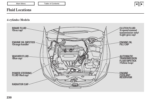
Fluid Locations
4-cylinder Models
BRAKE FLUID (Gray cap)
Table of Contents
ENGINE OIL DIPSTICK (Orange handle)
WASHER FLUID (Blue cap)
POWER STEERING FLUID (Red cap) RADIATOR CAP
v w
Main Menu
Table of Contents
6-cylinder Models
ENGINE OIL DIPSTICK (Orange loop)
ENGINE OIL FILL CAP
WASHER FLUID (Blue cap)
POWER STEERING FLUID (Red cap)
三轴五档汽车变速器-说明书

摘 要本设计的任务是设计一台用于轿车上的 FR 式的手动变速器。
本设计采用中 间轴式变速器,该变速器具有两个突出的优点:一是其直接档的传动效率高,磨 损及噪声也最小; 二是在齿轮中心距较小的情况下仍然可以获得较大的一档传动 比。
根据轿车的外形、轮距、轴距、最小离地间隙、最小转弯半径、车辆重量、 满载重量以及最高车速等参数结合自己选择的适合于该轿车的发动机型号可以 得出发动机的最大功率、最大扭矩、排量等重要的参数。
再结合某些轿车的基本 参数,选择适当的主减速比。
根据上述参数,再结合汽车设计、汽车理论、机械 设计等相关知识,计算出相关的变速器参数并论证设计的合理性。
它功用是:①改变传动比,扩大驱动轮转矩和转速的变化范围,以适应经常 变化的行驶条件,如起步、加速、上坡等,同时使发动机在有利的工况下工作;②在发动机旋转方向不变的前提下,使汽车能倒退行驶;③利用空档,中断动力 传递,以使发动机能够起动、怠速,并便于发动机换档或进行动力输出。
这台变 速器具有五个前进档(包括一个超速档五档)和一个倒档,并通过锁环式同步器 来实现换档。
关键词: 变速器;锁环式同步器;传动比;中间轴ABSTRACTThe duty of this design is to design a FR type manual transmission used in the saloon,It’s the countershafttype transmission gearbox.This transmission has twoprominent merits: Firstly,the transmission efficiency of the direct drive keeps off high, the attrition and the noise are also slightest;Secondly ,it’s allowed to obtain in the biger gear ratio of the first gear when the center distance is smaller.According to the contour,track,wheel base,the smallest ground clearance,the smallest turning radium,the vehicles weight, the allup weight as well as the highest speed and so on, union the choosing engine model we can obtain the important parameters of the max power,the max torque, the displacement and so on. According to the basic parameters of the certain saloon,choose the suitable final drive ratio.According to the above parameters,combining the knowledge of automobile design, automobile theory, machine design and so on, calculate the correlated parameters of the gearbox and proof the rationality of the design.Its function is:①Changing gear ratio,expanding the torque of the driving wheel and the range of the rotational speed,to adapt the travel condition which frequently changes, like start, acceleration, climbing and so on, simultaneously causes the engine to work under the advantageous operating mode;②Under the premise of the invariable rotation, enables the automobile to travel back;③Using neutral, severances the power transmission, to make the engine start, idle, and is advantageous for the engine to shift gears or to carry on the dynamic output. This gearbox has five (including over drive—fifth gear) and a reverse gear, and through the inertial type of synchronizer to realize shift gears.KEY WORDS: transmission; inertial type of synchronizer;gear ratio;countershaft第一章 前言现在,每当人们观看 F1 大赛,总会被那种极速的感觉所折服。
《机械制造技术课程设计-CA10B解放汽车第四速及第五速变速叉加工工艺及钻M10螺纹孔夹具设计【全套图纸】》
机械制造技术课程设计题 目:变速叉钻 螺纹孔夹具设计院 别: 机 电 学 院专 业: 机械设计制造及其自动化姓 名:学 号:指导教师:日 期: 2013年 月 日10M目录目录 (2)课程设计任务书 (3)序言 (4)一、零件的分析 (4)㈠零件的作用 (5)㈡零件的工艺分析 (5)二、夹具的定位结构方案设计 (7)㈠设计定位方案及定位误差分析 (7)①方案一 (9)②方案二 (9)③方案三 (10)㈡确定定位方案 (11)三、定位元件的设计 (11)i.定位心轴的设计 (11)ii.定位销的设计 (12)四、导向装置设计 (13)i.快换钻套选用 (14)ii.钻套用衬套选用 (15)iii.钻套螺钉选用 (15)五、夹紧机构设计 (16)㈠确定夹紧机构 (16)㈡夹紧元件的设计 (16)㈣夹紧力的计算 (18)㈤校核夹紧的强度 (20)六、夹具体设计 (20)七、绘制总图及确定主要尺寸、公差和技术要求 (21)八、总结 (22)九、参考资料 (23)机械制造技术基础课程设计任务书全套图纸,加153893706设计题目设计CA10B解放汽车第四速及第五速变速叉加工M10螺纹孔的专用钻床夹具设计内容:1、零件图1张2、夹具结构设计装配图1张3、夹具结构设计零件图1~2张4、课程设计说明数1份序言机械制造技术基础课程设计是在我们学完了大学的全部基础课、技术基础可以及大部分专业课之后进行的。
这是我们在进行毕业设计之前对所学各课程的一次深入的综合性链接,也是一次理论联系实际的训练。
因此,它在我们的大学学习生活中占有十分重要的地位。
就我个人而言,我希望能通过这次课程设计对自己未来将从事的工作进行一次适应性训练,从中锻炼自己分析问题的能里,为今后参加祖国的现代化建设打下一个良好的基础。
一、零件的分析㈠零件的作用题目所给定的零件是CA10B解放汽车第四速及第五速的变速叉(见图1-1),应用在汽车变速箱的换挡机构中。
DF5S550系列变速箱使用说明书
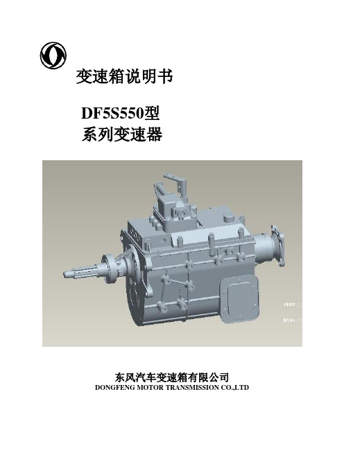
变速箱说明书DF5S550型系列变速器东风汽车变速箱有限公司DONGFENG MOTOR TRANSMISSION CO.,LTD欢迎惠顾!对于您购买使用DF5S550型系列汽车变速器表示感谢。
为了您使用方便及确保充分发挥其性能,我们特别建议您在使用、维修之前,请仔细阅读本使用说明书,并留心列举的注意事项,以便更好地操作和保养变速器。
公司简介东风汽车变速箱有限公司是东风汽车有限公司下属的零部件子公司,是中国最大的汽车变速箱生产企业之一。
公司拥有各类工艺设备1300余台套,年综合生产能力达16.5万辆份。
公司先后通过了ISO9001:2000质量体系认证和ISO14001环境体系认证。
与东风汽车工程研究院联合成立了变速箱研发中心,不断开发适应性产品满足用户的需求。
公司现有产品分DF5S300、DF5S360、DF5S470、DF5S550、DF5S1050、DF6S650/750、DF6S900/1000、DF8S1200、DF9S1600等九个系列400多个品种,其输入扭距覆盖300-1600N.M,宽系列的产品格局可覆盖重、中、轻、客等系列车型。
公司产品除配套东风公司外,还为国内几十家汽车厂商供应变速箱产品。
公司科学的管理模式,精良的工艺设备,先进的检测手段,完善的质量保证体系为产品的高质量提供了可靠保障;优质的售后服务,赢得了用户信赖。
2000年,“东风牌”变速箱荣获中国市场商品质量调查齿轮行业“十佳品牌”第一名;2003年,“东风牌”变速箱再次荣获中国市场汽车行业“品牌、质量、价格、服务”专项调查“十佳品牌”和“质量美誉度”第一名。
本维修使用说明书详尽介绍了DF5S550系列变速箱的匹配、应用、维护、使用等知识。
供主机厂匹配,售后服务工作的参考。
东风汽车变速箱有限公司研发中心负责技术咨询、解释,营销中心负责销售和售后服务工作。
联络电话(Tel):0719-*******传真(Fax) :0719-*******变速箱主要技术参数1.主要技术参数超速档2箱代码:17JK3-00030直接档1箱代码:17JK1-00030直接档2箱代码:17JK2-00030直接档3箱代码:17JK4-000302.型号说明DF 5S 550变速箱输入扭矩550N.M前进档位数东风汽车公司缩写DF5S550系列变速箱传动系统图(见下图)变速箱结构特点变速箱结构是三轴式、单中间轴、定轴传动。
IV档变速叉课程设计
IV档变速叉课程设计一、课程目标知识目标:1. 学生能理解IV档变速叉的基本结构及其在汽车变速系统中的作用。
2. 学生能掌握IV档变速叉的工作原理,包括变速叉的移动、齿轮的啮合与脱离过程。
3. 学生能了解IV档变速叉的材料、加工工艺及其对变速性能的影响。
技能目标:1. 学生能够运用所学的知识,分析并解决IV档变速叉在实际应用中出现的问题。
2. 学生能够通过观察、实践等方式,掌握检测和维护IV档变速叉的方法。
3. 学生能够运用绘图工具,绘制出IV档变速叉的结构示意图。
情感态度价值观目标:1. 学生培养对汽车变速系统及其零部件的兴趣,激发学习汽车工程技术的热情。
2. 学生在学习和实践过程中,培养团队协作、沟通交流的能力,增强解决问题的信心。
3. 学生通过了解我国汽车变速技术的发展,培养民族自豪感,树立为我国汽车工业发展贡献力量的信念。
课程性质:本课程为汽车维修与检测专业课程,结合学生的实际需求和教学要求,注重理论联系实际,强调实践操作能力的培养。
学生特点:学生为中职二年级学生,已具备一定的汽车基础知识,动手能力强,但对复杂变速系统的理解尚需加强。
教学要求:教师应注重启发式教学,引导学生主动探究,通过实践操作巩固所学知识,提高学生的综合运用能力。
同时,关注学生的个体差异,给予个性化指导,确保课程目标的实现。
二、教学内容1. IV档变速叉的结构与功能- 变速叉的结构组成- 各部件的作用及相互关系- IV档变速叉在汽车变速系统中的应用2. IV档变速叉的工作原理- 变速叉的移动原理- 齿轮的啮合与脱离过程- 变速叉与齿轮之间的力学关系3. IV档变速叉的材料与加工工艺- 常用材料的特点及选择- 加工工艺对变速性能的影响- 现代加工技术在实际应用中的优势4. IV档变速叉的检测与维护- 检测方法及注意事项- 常见故障分析与排除- 维护保养措施及周期5. 实践操作- 观察和分析IV档变速叉实物- 绘制IV档变速叉结构示意图- 模拟变速叉的组装与拆解过程教学大纲安排:第一课时:IV档变速叉的结构与功能第二课时:IV档变速叉的工作原理第三课时:IV档变速叉的材料与加工工艺第四课时:IV档变速叉的检测与维护第五课时:实践操作教学内容与课本关联性:以上教学内容紧密结合教材中关于汽车变速系统的相关章节,确保学生所学知识的系统性和科学性。
5速手动变速箱使用指南说明书

5-speed Manual TransmissionThe manual transmission is syn-chronized in all forward gears for smooth operation. It has a lockout so you cannot shift directly from Fifth to Reverse. When shifting up or down, make sure you push the clutch pedal down all the way, shift to the next gear, and let the pedal up gradually. When you are not shifting, do not rest your foot on the clutch pedal. This can cause your clutch to wear out faster.Come to a full stop before you shift into reverse. You can damage the transmission by trying to shift into reverse with the car moving.Depress the clutch pedal and pause for a few seconds before putting it in reverse, or shift into one of the forward gears for a moment. This stops the gears so they won't "grind" .You can get extra braking from the engine when slowing down byshifting to a lower gear. This extra braking can help you maintain a safe speed and prevent your brakes from overheating while going down a steep hill. Before downshifting,make sure engine speed will not go into the red zone in the lower gear.Refer to the Maximum Speeds chart.Recommended Shift Points Drive in the highest gear that lets the engine run and accelerate smoothly. This will give you the best fuel economy and effective emissions control. The following shift points are recommended:CONTINUED DrivingRapid slowing or speeding-up can cause loss of control on slippery surfaces, if you crash,you can be injured.Use extra care when driving on slippery surfaces.5-speed Manual Transmission, Automatic TransmissionMaximum SpeedsThe speeds in this table are the maximums for the given gears. If you exceed these speeds, the engine speed will enter into the tachometer's red zone. If thisoccurs, you may feel the engine cut in and out. This is caused by a limiter in the engine's computer controls. The engine will run normally when you reduce the RPM below the red zone.(US: DX, LX, Canada: LX, EX)(US: EX, Canada: EX-V)Automatic Transmission Your Honda's transmission has four forward speeds, and is electro-nically controlled for smoother shifting. It also has a "lock-up"torque converter for better fuel economy. You may feel what seems like another shift when the con-verter locks.DrivingShift Lever PositionsAutomatic TransmissionThis display is on the instrument panel. It shows you the position of the shift lever.The shift lever has seven positions.It must be in Park or Neutral to start the engine. When you are stopped in D4, D3, 2,1 or R, press firmly on the brake pedal and keep your foot off the accelerator pedal.Park (P) — This position mechani-cally locks the transmission. Use Park whenever you are turning off or starting the engine. To shift out of Park, you must press on the brake pedal and have your foot off the accelerator pedal. Press the release button on the side of the shift lever to move it.You must also press the release button to shift into Park. To avoid transmission damage, come to a complete stop before shifting into Park. The shift lever must be in Park before you can remove the key from the ignition switch.If you have done all of the above and still cannot move the lever out of Park, see Shift Lock Release on page 105.DrivingSHIFT LEVERCONTINUEDAutomatic TransmissionReverse (R) — To shift to Re-verse from Park, see the explana-tion under Park. To shift to Re-verse from Neutral, come to a com-plete stop and then shift. Press the release button before shifting into Reverse from Neutral.Neutral (N) — Use Neutral if you need to restart a stalled engine, or if it is necessary to stop briefly with the engine idling. Shift to Park posi-tion if you need to leave the car for any reason. Press on the brake pe-dal when you are moving the shift lever from Neutral to another gear.Drive (D4) — Use this position for your normal driving. The transmis-sion automatically selects a suita-ble gear for your speed and acceler-ation. You may notice the transmis-sion shifting up at higher speeds when the engine is cold. This helps the engine warm up faster.Drive (D3) — This position is simi-lar to D4, except only the first three gears are selected. Use D3 toprovide engine braking when going down a steep hill. D3 can also keep the transmission from cycling between third and fourth gears in stop-and-go driving.For faster acceleration when in D3or D4, you can get the transmission to automatically downshift by push-ing the accelerator pedal to the floor. The transmission will shift down one or two gears, depending on your speed.Second (2) — To shift to Second,press the release button on the side of the shift lever. This position locks the transmission in second gear. It does not downshift to first gear when you come to a stop.Second gives you more power when climbing, and increased engine braking when going down steephills. Use second gear when start-ing out on a slippery surface or in deep snow. It will help reduce wheelspin.Whenever you move the shift lever to a lower gear, the transmission downshifts only if the engine's redline will not be exceeded in the lower gear.First (1) — To shift from Second to First, press the release button on the side of the shift lever. With the lever in this position, the transmis-sion locks in First gear. By upshift-ing and downshifting through 1, 2,D3 and D4, you can operate this transmission much like a manual transmission without a clutch pedal.DrivingAutomatic TransmissionMaximum SpeedsThe speeds in this table are the maximums for the given position.If you exceed these speeds, the engine speed will enter into the tachometer's red zone. If thisoccurs, you will feel the engine cut in and out. This is caused by a limiter in the engine's computer controls. The engine will run normally when you reduce the RPM below the red zone.(US: EX, Canada: EX-V)Shift Lock ReleaseThis allows you to move the shift lever out of Park if the normal method of pushing on the brake pedal and pressing the release button does not work.1. Set the Parking brake.2. Remove the key from the ignition switch.3. Insert the key in the Shift Lock Release slot next to the shift lever.4. Push down on the key while you press the release button and move the shift lever out of Park to Neutral.SHIFT LOCK RELEASE SLOT5. Remove the key from the Shift Lock Release slot. Depress the brake pedal and restart the engine.If you need to use the Shift Lock Release, it could mean your car is developing a problem. Have the car checked by your Honda dealer.DrivingRELEASE BUTTON(US: DX, LX, Canada: LX, EX)。
解放汽车第四速及第五速变速叉_说明书

参照<<机械加工工艺手册>>表 3.1-56,因为其公差等级太低,可直接铣. 2. 槽的侧面 参照<<机械加工工艺手册>>表 3.1-56,其加工余量 Z=2mm.
0.045 3. Φ19 0 mm 孔的两个上端面
参照<<机械加工工艺手册>>表 3.1-56, 其加工余量 Z=2mm.
(一) 确定毛坯的制造形式 零件材料为 20 钢,零件经常拨动齿轮承受变载荷和冲击性载荷,因此应选用锻件, 以使金属纤维尽量不被切断,保证零件工作可靠.因为为大批量生产,且零件的轮廓尺寸 不大,故采用模锻成型.这从提高生产率,保证加工精度上考虑,也是应该的. (二) 基面的选择 基面选择是工艺规程设计中的重要工作之一,它对零件的生产是非常重要的. 1.粗基准的选择
f z 0.08mm / r
当采用高速钢车刀时,切削速度:V=16mm/min.
ns tm
工序Ⅴ
1000v 1000*27 318r / min 16 3.14*16 l l1 12 0.20 min 108 nw f m
0.045 钻铰Φ19 0 mm 孔,并倒角 1*450 两端. 0.045 1.钻孔Φ18.5 0 mm
这样可以修正由于基准不重合造成的加工误差,同时也照顾了加工路线方便的特点,因 此最终确定如下: 工序Ⅰ
0.24 0.045 粗铣 16 0 mm 槽,以Φ19 0 mm 孔的外轮廓为粗基准定位,选用 XA6132 型万能
升降台铣床及专用夹具. 工序Ⅱ
0.24 0.045 粗铣 16 0 mm 槽的两侧面,以Φ19 0 mm 孔的外轮廓以及距槽底 32mm 的面为
5档变速叉课程设计说明书
序言机械制造工艺学课程设计是我在学习基础课、专业基础课和部分专业课后进行的,是对所学课程一次深入的综合性复习,也是一次理论联系实际的训练。
对我个人而言,希望通过这次课程设计对我的专业技术水平及解决实际问题的能力有所提升,并且对我所从事的工作从理论和实际两个方面都有一个质的提高。
由于能力有限,设计尚有许多不足之处,恳请老师给予指导。
第1章零件的分析本次课程设计题目所给的是五档变速叉,它位于发动机的速机构上,主要起换挡作用。
1.1 零件的工艺分析依据零件图纸加工面与非加工面分析零件加工表面及加工面之间的位置要求:✓孔φ22mm;✓孔φ8mm;✓叉头φ22mm成形面;✓叉头平面;✓叉口内平面;✓孔φ8mm中心与孔φ22mm中心在水平方向上23±0.25mm;(见零件图)✓孔φ8mm中心与孔φ22mm中心在垂直方向上78±0.25mm;(见零件图)✓φ8mm两孔轴线同轴度不大于0.2mm;✓φ8mm两孔公共轴线对尺寸23mm的平面内φ22mm的表面的平行度在长度100mm 上不大于0.2mm;✓φ8mm两孔公共轴线对尺寸78mm的平面的不平行度在长度100mm上不大于0.4mm;✓φ8mm和φ15mm两表面间壁厚应为2.5--4.0mm,其余应不小于2.5mm。
1.2 生产类型确定生产类型:批量生产加工设备:通用设备、采用专用工装第2章工艺规程设计2.1 确定毛坯的制造形式零件材料为45钢,结构比较简单;考虑到其在工作过程中常受交变载荷及冲击性载荷;生产类型为批量生产;故采用精密模锻毛坯,以使金属纤维尽量不被切断,保证零件工作可靠,也可提高生产率。
毛坏公差参考GB/T12362-2003钢质模锻件公差及加工余量。
2.2 选择定位基准基准选择的正确与合理,可以使加工质量得以保证,生产率得以提高。
由零件工艺分析知:孔φ22mm中心是加工φ8mm孔及叉头φ22mm的设计基准;叉口中心是加工叉口、叉头平面的设计基准。
- 1、下载文档前请自行甄别文档内容的完整性,平台不提供额外的编辑、内容补充、找答案等附加服务。
- 2、"仅部分预览"的文档,不可在线预览部分如存在完整性等问题,可反馈申请退款(可完整预览的文档不适用该条件!)。
- 3、如文档侵犯您的权益,请联系客服反馈,我们会尽快为您处理(人工客服工作时间:9:00-18:30)。
机械制造工艺学课程设计设计题目设计“解放汽车第四速及第五速变速叉”零件的机械加工工艺规程及工艺装备内装1、零件图一张2、毛坯图一张3、机械加工工艺过程综合卡片一张4、夹具总装图一张5、夹具零件图一张手绘两张cad6、说明书一份工程机械学院25041004班设计者15 王东升指导教师张接信、高琳完成日期2014 年1 月15 日成绩(长安大学)《机械制造工艺学》课程设计说明书设计题目:设计“解放汽车第四速及第五速变速叉”零件的机械加工工艺规程及工艺装备设计者:王东升指导教师:高琳长安大学机制教研室2014年1月15日长安大学机械制造工艺学课程设计任务书题目:设计拨叉(CA6140车床)零件的机械加工工艺规程及工艺装备内容:1.零件图1张2.毛坯图1张3.机械加工工艺过程综合卡片1张4.夹具装配图1张5.夹具零件图3张6.课程设计说明书1份班级:25041004班学生:王东升指导教师:高琳教研室主任:张接信2014年1月目录一.序言二.零件的分析(一)零件的作用(二)零件的工艺分析三.工艺规程设计(一)确定毛坯的制造形式(二)基面的选择(三)制订工艺路线(四)机械加工余量,工序尺寸及毛坯尺寸确定(五)确定切削用量及基本工时四.夹具设计(一)定位基准的选择(二)切削力及夹紧力计算(三)定位误差分析(四)夹具设计及操作的简要说明五.参考文献一.序言机械制造工艺学课程设计是在大学全部基础课,技术基础课以及大部分专业课完成以后进行的.这是我们在进行毕业设计之前对所学各课程的一次深入的综合性的总复习,也是一次理论联系实际的训练,因此,它在我们大学四年的的学习中占有重要地位.就我个人而言,希望能通过这次课程设计对自己即将从事的工作进行一次适应性训练,从中锻炼自己分析问题,解决问题的能力.由于能力有限,设计尚有诸多不足之处,恳请各位老师多多指教.二.零件的分析(一) 零件的作用题目所给定的零件是解放汽车第四速及第五速变速叉,它位于变速箱中,主要重用是拨动变速箱中的齿轮,使汽车达到变速的目的. (二) 零件的工艺分析此变速叉共有两组加工表面,它们之间有一定的位置要求,现分述如下:1.以Φ19045.00+mm 孔为中心的加工表面.这组加工表面包括:Φ19045.00+mm 孔及其倒角,孔上端尺寸为1624.00+mm 的槽,槽的外侧厚度为10.8mm 的两个侧面, Φ19045.00+mm 孔的上端距其中心12mm 的两个端面,还有孔下端M10的螺纹孔.2.以Φ82.210+mm 孔为中心的加工表面.这组加工表面包括: Φ82.210+mm 的孔及其倒角, Φ82.210+mm 的孔的侧面,距M10螺纹孔中心线63.7mm.这两组加工表面有着一定的位置要求,主要是:Φ82.21+mm孔与其外端面垂直度公差为0.1mm.由以上分析可知,对于这两组加工表面而言,可以先加工其中一组表面,然后借助专用夹具加工另一组表面,并保证他们之间的位置精度要求. 三.工艺规程设计(一)确定毛坯的制造形式零件材料为20钢,零件经常拨动齿轮承受变载荷和冲击性载荷,因此应选用锻件,以使金属纤维尽量不被切断,保证零件工作可靠.因为为大批量生产,且零件的轮廓尺寸不大,故采用模锻成型.这从提高生产率,保证加工精度上考虑,也是应该的.(二)基面的选择基面选择是工艺规程设计中的重要工作之一,它对零件的生产是非常重要的.1.粗基准的选择现选取Φ19045.0+mm孔的外轮廓不加工面作为粗基准,利用一组共两个V形块夹持外轮廓做为主要定位面,以消除自由度.2.精基准的选择主要考虑基准重合的问题,当设计基准与工序基准不重合时,应该进行尺寸换算,这在以后还要专门计算,此处不再重复.(三)制订工艺路线制订工艺路线的出发点,应当是使零件的几何形状,尺寸精度及位置精度的技术要求能得到合理的保证.爱生产纲领已确定为大批量生产的条件下,可以考虑采用万能性机床以及专用夹具,并尽量使工序集中来提高生产率.除此之外,还应当考虑经济效果,以便使生产成本尽量降低. 工艺路线工序Ⅰ 粗铣1624.00+mm 槽,以Φ19045.00+mm 孔定位. 工序Ⅱ 粗铣1624.00+mm 槽的两侧面,以Φ19045.00+mm 孔定位.工序Ⅲ 粗铣距Φ19045.00+mm 中心12mm 的两个端面,以Φ19045.00+mm 孔及1624.00+mm 槽底为基准.工序Ⅳ 1624.00+mm 槽两端1.5*450倒角. 工序Ⅴ 钻铰Φ19045.00+mm 孔并倒角.工序Ⅵ 钻距槽(1624.00+mm)12mm 底面M10螺纹孔并倒角.工序Ⅶ 攻螺纹M10.工序Ⅷ 粗铣Φ82.210+mm 孔的两端面. 工序Ⅸ 粗镗Φ81.710+mm 孔. 工序Ⅹ 精镗Φ82.210+mm 孔. 工序Ⅺ Φ82.210+mm 孔1*450倒角 工序Ⅻ 精铣Φ82.210+mm 孔的两端面.工序ⅩⅢ 终检.上述方案主要是以Φ19045.00+mm 孔位基准,来加工1624.00+mm 槽,M10螺纹,槽的两侧面,这样可以修正由于基准不重合造成的加工误差,同时也照顾了加工路线方便的特点,因此最终确定如下:工序Ⅰ 粗铣1624.00+mm 槽,以Φ19045.00+mm 孔的外轮廓为粗基准定位,选用XA6132型万能升降台铣床及专用夹具.工序Ⅱ 粗铣1624.00+mm 槽的两侧面,以Φ19045.00+mm 孔的外轮廓以及距槽底32mm 的面为基准,选用XA6132型万能升降台铣床及专用夹具.工序Ⅲ 粗铣Φ19045.00+mm 孔上端两端面,以Φ19045.00+mm 孔定位,选用XA6132型万能升降台铣床及专用夹具.工序Ⅳ 1624.00+mm 槽1.5*450倒角,选用C620-1车床及专用夹具. 工序Ⅴ 钻铰Φ19045.00+mm 孔并倒角.以Φ19045.00+mm 孔及端面定位,选用Z5125立式钻床及专用夹具.工序Ⅵ 钻距槽(1624.00+mm)12mm 底面M10螺纹孔并倒角.以Φ19045.00+mm 孔及1624.00+mm 槽底定位,选用Z5125立式钻床及专用夹具.工序Ⅶ 攻螺纹M10.工序Ⅷ 粗铣Φ82.210+mm 孔的两端面.以Φ19045.00+mm 孔定位,选用XA6132型万能升降台铣床及专用夹具.工序Ⅸ 粗镗Φ81.710+mm 孔.以Φ19045.00+mm 孔及1624.00+mm 槽为基准,选用T740双面卧式金刚镗床及专用夹具.工序Ⅹ 精镗Φ82.210+mm 孔. .以Φ19045.00+mm 孔及1624.00+mm 槽为基准,选用T740双面卧式金刚镗床及专用夹具.工序Ⅺ Φ82.210+mm 孔1*450倒角.选用C620-1型车床及专用夹具. 工序Ⅻ 精铣Φ82.210+mm 孔的两端面. 以Φ19045.00+mm 孔定位,选用XA6132型万能升降台铣床及专用夹具.工序ⅩⅢ 终检.(四) 机械加工余量,工序尺寸及毛坯尺寸确定.“变速叉”零件材料为20钢,毛坯重量约1.5Kg,生产类型为大批量生产,采用锻锤上合模锻毛坯.根据上述资料及加工工艺,分别确定各加工表面的机加工余量,工序尺寸及毛坯尺寸如下:1. 1624.00+mm 槽参照<<机械加工工艺手册>>表 3.1-56,因为其公差等级太低,可直接铣.2. 槽的侧面参照<<机械加工工艺手册>>表3.1-56,其加工余量Z=2mm.3. Φ19045.00+mm 孔的两个上端面参照<<机械加工工艺手册>>表3.1-56, 其加工余量Z=2mm.4. Φ82.210+mm 孔的两侧面,铣削公差-0.22mm.参照<<机械加工工艺手册>>表3.1-56, 其加工余量Z=2mm.精铣余量:单边0.7mm(见<<工艺设计手册>>表8-31),铣削余量:Z=2.0-0.7=1.3mm,锻件偏差3.15.0+-mm 。
由于设计规定的零件为大批量生产,应该采用调整法加工.因此在计算最大,最小加工余量时,应按调整法加工方式予以确定.5. Φ19045.00+mm 孔参照<<机械加工工艺手册>>, 其加工余量2Z=2mm.钻孔Φ18.5045.00+mm,铰孔Φ19045.00+mm. 6. Φ82.210+mm 孔参照<<机械加工工艺手册>>, 其加工余量2Z=2.5mm.粗镗Φ81.710+mm,精镗Φ82.210+mm.厚度为8mm 的两端面尺寸加工余量和工序间余量. 毛坯名义尺寸: 8+2*2=12mm毛坯最大尺寸: 12+1.3*2=14.6mm 毛坯最小尺寸: 12-0.5*2=11mm 粗铣后最大尺寸: 8+0.7*2=9.4mm 粗铣后最小尺寸: 9.4-2*0.22=8.96mm精铣尺寸与零件尺寸相符,即82.03.0+-mm.(五) 确定切削用量及基本工时工序Ⅰ 粗铣1624.00+mm 槽,保证尺寸1624.00+mm.f z =0.06mm/齿切削速度:参考有关手册,V=22.8m/min. 采用W18Cr4V 立铣刀,d w =16mm,Z=3,则: n s =dw v π1000=16*14.38.22*1000=454r/min f m =f z zn w =0.06*3*420=75.6mm/min1222l l l mm ++= 12220.29min 75.6m ml l l t f ++=== 工序Ⅱ 粗铣1624.00+mm 槽两侧面。
0.12/z f mm =齿切削速度:参考有关手册,V=27m/min 。
采用高速钢三面刃圆盘铣刀,80w d mm =,Z=10。
10001000*27107.5/min 3.14*80s w v n r d π=== 0.12*10*90108/min m z w f f zn mm === 1260l l l mm ++= 12600.56min 108m m l l l t f ++=== 工序Ⅲ粗铣Φ19045.00+mm 孔上端两端面。
0.12/z f mm =齿切削速度:参考有关手册,确定V=27m/min 。
采用高速钢三面刃圆盘铣刀,80w d mm =,Z=10。
10001000*27108/min 3.14*80s w v n r d π=== 0.12*10*90108/min m z w f f zn mm === 1212l l l mm ++= 12120.11min 108m m l l l t f ++=== 工序Ⅳ1624.00+mm 槽1.5*450倒角,选用卧式车床C620-1, 0.08/z f mm r =当采用高速钢车刀时,切削速度:V=16mm/min .10001000*27318/min 16 3.14*16s v n r π===1120.20min 108m w m l l t n f +=== 工序Ⅴ钻铰Φ19045.00+mm 孔,并倒角1*450两端. 1.钻孔Φ18.5045.00+mm 0.35~0.430.35/z f mm r ==18.5w d mm =,V=17m/min.采用高速钢钻头, 10001000*17285/min 16 3.14*18.5s v n r π=== 1240l l l mm ++=12400.41min 285*0.35m w m l l l t n f ++=== 2.铰孔Φ19045.00+mm. 0.7/z f mm r =采用高速钢绞刀,V=14.7m/min.10001000*14.7246/min 19 3.14*19s v n r π===12450.28min 250*0.7m w m l l l t n f ++=== 3.Φ19045.00+mm 孔倒角1*450两端.采用900锪钻,为缩短辅助时间,取倒角时的主轴转速与铰孔相同.246/min s n r = 工序Ⅵ钻M10螺纹孔并倒角1200 0.1/z f mm r =采用麻花钻,V=20m/min.10001000*20637/min 10*3.14s v n r d π===12150.24min 637*0.1m w m l l l t n f ++=== 工序Ⅶ攻螺纹M10.V=6m/min 10001000*20238/min 10*3.14s v n r d π=== 12160.24min 195*1m w m l l l t n f ++=== 工序Ⅷ 粗铣Φ82.210+mm 孔端面.0.2/z f mm r =采用高速钢圆柱铣刀,100w d mm =,Z=10,V=20m/min10001000*2063.7/min 100*3.14s v n r d π===60600.75min 0.2*65*100m z w w t f n d === 工序Ⅸ粗镗Φ81.710+mm 孔 1.0/z f mm r =采用双刃镗刀,V=40m/min .10001000*40156/min 81.7*3.14s v n r d π===0.96min m t = 工序Ⅹ精镗Φ82.210+mm 孔. 0.6/z f mm r =V=35m/min10001000*35136/min 82.2*3.14s v n r d π===0.64min m t = 工序ⅪΦ82.210+mm 孔1*450倒角.0.08/z f mm r =V=16m/min 10001000*1662/min 82.2*3.14s v n r d π=== 50.48min 0.08*65m t == 工序Ⅻ 精铣Φ82.210+mm 孔的两端面0.06/z f mm =齿采用高速钢圆柱铣刀,V=31m/min .100w d mm = 10z = 10001000*3198/min 100*3.14s v n r d π=== 601min 58.8m t == 工序ⅩⅢ 终检。