带式输送机技术论文中英文对照资料外文翻译文献
普通带式输送机的毕业设计论文(含中英文翻译)[管理资料]
![普通带式输送机的毕业设计论文(含中英文翻译)[管理资料]](https://img.taocdn.com/s3/m/0bd709bbcf84b9d529ea7ac5.png)
毕业设计说明书普通带式输送机的设计作者: 学号:学院(系):专业:指导教师:评阅人:2006年6月普通带式输送机的设计摘要本文在参考常规下运带式输送机设计方法的基础上,分析了常见驱动方式和制动方式用于长运距、大运量下运带式输送机上的优缺点,提出该运输机可采用的驱动和制动方式;分析了常见软起动装置及其选型方法,归纳总结出长运距、大运量变坡输送下运带式输送机设计中的关键问题和可靠驱动方案和制动方式优化组合的可行方案;通过常规设计计算,提出了合理确定张紧位置、张紧方式及张紧力大小的方法;对驱动装置及各主要部件进行了选型并校核。
长距离变坡下运带式输送机运行工况复杂,在设计方面需考虑各种可能的工况,并计算最危险工况下输送机的各项参数,同时为保证运行过程中输送机各组成部分能适应载荷及工况的变化需将拉紧力统一,然后重新计算各工况下输送机参数,最终确定整机参数。
本论文对长运距、大运量变坡下运带式输送机,综合考虑各方面的因素,采用合理的驱动方案、制动方式和软启动装置组合,有效保证长运距、大运量变坡下运带式输送机的可靠运行。
关键词:带式输送机下运长距离变坡STUDY ON COMMON TRANSPORTING BELT-CONVEYER ABSTRACT Based on the design method for the conventional Downwards Transporting Belt-Conveyer (DTBC), the common used driving and braking devices were analyzed in the condition of long-distance and heavy-capacity. The driving and braking types were presented for this kind of conveyer. The soft-starting devices and their type-selection were analyzed. The key points were summarized for designing the long-distance, heavy-capacity DTBC used in varying slope environment. The reliable combined scheme of driving and braking units was put forward. The methods for determining the tensioning location, type and the amount of tensioning force based on the results of conventional calculations. The criterion was summarized for selecting driving device and the main components in the conveyer.Due to the complicated operational condition of long-distance and varying slope DTBC, it is necessary to consider every kind of possible working conditions during its design and calculate the parameters in the most dangerous condition. At the same time, it is necessary to uniform the tensioning force in order to suit the variations of the load and condition. Then the conveyer's parameters should be re-calculated under various conditions and the parameters should be determined finally.The research of this paper shows that by using reasonable combination of driving scheme, braking mode and soft-starting device and by determining the schemes for braking and soft-starting from the dynamical analysis and simulation, the reliable operation could be guaranteed for the long-distance, heavy-capacity and varying slope DTBC.Key word Belt-conveyer, Downwards transportation, long-distance, Varying slope目录1 绪论 (1) (2) (2) (2) (3) (3) (4) (4) (5) (5) (5) (6)、大运量下运带式输送机关键技术分析研究 (6)、制动方案的分析 (6)3长距离、大运量下运带式输送机关键技术的分析 (7) (7) (7) (8)4 长距离大运量下运带式输送机的设计 (11)带式输送机原始参数 (11)带式输送机的设计计算 (11)............................................................1 1 .....................................................................1 2 (12)................................................1 3 .....................................................................1 3 ............................................................1 3 ........................................................................1 4 .....................................................................1 5 ................................................1 6 最大发电状态下张力计算 (16)最大电动状态下张力计算 (19) (20)......................................................2 1 ............................................................2 4 滚筒的选择与减速器的选择 (24)...............................................................2 4 ..................................................................2 4 ........................................................................2 4 制动器装置的选择 (25)................................................2 5 (27) (27) (28)目前主要的软起动装置原理与性能 (28)软起动装置的选用 (31) (31).....................................................................3 2 .........................................................3 2 ........................................................................3 2 5 结论 (34)致谢 (35)参考文献 (36)外文文献原文译文1 绪论带式输送机的最新发展方向时一呈现长距离、大运量、高速度、集中控制等特点。
高速带式输送机的设计——外文翻译、中英文翻译
附件A高速带式输送机的设计G. Lodewijks,荷兰摘要本文主要探讨高速带式输送机设计方面的问题。
带式输送机的输送量取决于输送带的速度、传送带宽度和托辊槽形角。
然而输送带速度的选择又受到各种实际条件的限制,在本文有这方面的讨论。
输送带速度也影响传送带的性能,例如它的能源消耗和它连续运行的稳定性。
一种计算输送带的能源消耗的方法就是通过考虑运输过程中的各种能量损耗来进行估算的。
输送带速度的不同使得安全系数的要求也各不相同,这也影响输送带所要求的强度。
一种新的计算输送带速度对安全系数的影响的方法在本文中被介绍。
最后,输送带速度的冲击对各组成部分的选择和对中转站设计的影响也在本文中被讨论。
1 概述过去的研究已经证实使用窄带输送机的经济可行性,输送带的速度变快要求输送带的宽度随之变宽,低速输送机适于长距离输送。
例如图[1] - [5]。
现在,传送带以8 m/s 的速度运行是没有问题的。
无论怎样,输送带速度在10m/s到20 m/s在技术上是(动态地)可行的,并且也许在经济上也是可行的。
本文将输送带速度在10和20 m/s之间的定义为高速。
输送带速度在10m/s之下的定义为低速。
使用高速输送带的目的并不在于它本身。
如果使用高速输送带不是经济上有利,或则,如果安全和可靠的操作没有保证的,那么就应该选择低速输送带。
输送带速度的选择是总的设计过程的一部分。
静态或稳定的设计方法决定了带式输送机的优化设计。
在这些设计方法中输送带被认为是刚性的,静止的。
这增加了输送机稳定运行的质量和也决定了带式输送机各零部件的尺寸。
稳定操作包括传送带稳定运行时的张力、相对各种物料载荷的能量消耗和相关的工作环境情况。
应该体会到找到最优的设计不是一次性的努力,而是一个反复的过程[6]。
优化设计,开始于优化的决心,终于符合要求的确定的控制算法和组成输送机的各零部件确定的位置和尺寸的大小,例如驱动,闸和飞轮,可由动态设计方法确定。
在这些设计方法中,也涉及动态分析,输送带可看作是一个三维的弹性体。
皮带输送机的驱动外文文献翻译、中英文翻译
外文资料Belt conveyor driveReduced voltage starting with increase of transmitting a driving power, during the acceleration control winding rotor induction motor around the rotor induction motor directly connected to the driving system; direct current (DC) motor transport most drive using a DC shunt motor; 1.2 hydraulic coupler; hydrodynamic coupling device is often referred to as hydraulic coupler, consists of three basic single; between the shaft and the driven shaft don't need any mechanical connection; a fixed charge hydraulic coupler fixed charge hydraulic coupler is in the structure is simple; the variable filled hydraulic coupler is also known for the moment type hydraulic coupler; spoon control of hydraulic couplingThe buck starts with the increase of the transmission drive power in the During acceleration control motor torque becomes more and more important. Because the motor torque is a function of the voltage, the voltage applied to the motor must be under control, general with silicon controlled rectifier (SCR} a buck start-up device, sincere and low voltage tension conveyor belt, and linear increase in supply voltage until the full voltage and maximum speed. However this starting in a way that does not produce stable acceleration, when the acceleration is completed, the motor voltage of the SCR control lock in the guide, themotor provides full pressure. Such control power can reach 750kW.Wound rotor induction motor winding rotor induction motor directly connected to the drive system Reducer through in the rotor windings of the motor in series resistance torque control of motor. In at the start of a transmission device, the resistor in series in the rotor to generate a low torque, when the conveyor belt speed, the resistance is gradually reduced steadily increasing torque. In multi drive system, an additional slip resistance may will always be connected in series in the circuit of rotor winding to help load sharing. The motor system design is relatively simple, but the control system may very complex, because they are based on the computer control of the resistive switching. Nowadays, the majority control system is custom designed to meet the specifications of transmission system around the rotor motor is suitable for 400 KVV above the system.Drive direct current (DC) motor transport most use DC shunt motor, the motor armature in the external connection. Controlled DC drive technique is generally used for SCR device, which allows continuous variable speed operation of DC drive system in machinery is simple, but design of electronic circuits, monitoring and control the whole system, compared to other soft start system is expensive, but in torque, load sharing and transmission for the main consideration occasions, it is a reliable, saving the cost of the DC motor general use in larger power conveying device, including should play the conveying belt tension control of multi drive Dynamic systems and transmission devices that require a wide range of transmission.Hydrodynamic coupling is often referred to as the hydrauliccoupler, consists of three basic units: as the impeller of the centrifugal pump, promote hydraulic turbine and put into the shell of the two power components. Fluid from the impeller to the turbine, on the driven shaft torque. Torque and speed because of the circulating fluid in driving Shaft and the driven shaft does not need any mechanical connection. This connection power generated by the decision to hydraulic coupling of the filling quantity, the torque is proportional to the input speed. Because in the fluid coupling output speed less than the input rate, the difference therebetween said to slip, generally 1% - 3%. Transmission power of up to several thousand kilowatts.A fixed charge hydraulic coupler fixed charge hydraulic coupler is in relatively simple in structure and has only limited the bending part of the conveying device most commonly used soft start device, the structure is relatively simple and low cost, can provide excellent soft start effect on now use most of the conveyor.Variable filled hydraulic coupler, also known as torque hydraulic coupler limited. Coupling of the impeller installed in the AC motor, turbine is installed on the driven gear for high-speed shaft on, containing the operating components of the axle box is installed on the driving base. Coupling the rotating shell with an overflow outlet allow the liquid to continuously from the working chamber midstream Into a separate auxiliary chamber, oil from the auxiliary chamber through a heat exchanger pump to control electromagnetic valve of coupler filling liquid quantity. In order to control the starting torque of the single motor driving system must be monitoring of AC motor current to the solenoid valve control provide feedback. Variable filled hydraulic coupler can beused in power delivery system and the power can reach thousands of kilowatts the drive is very complex both in mechanical, or electrical driving system at moderate cost.Spoon pipe control hydraulic coupler is also known for the variable speed fluid couplings. This hydraulic coupler is also by three standard coupling unit form, i.e., an impeller, a turbine and a A housing containing loop. This hydraulic coupler need outside the working chamber setting catheter (also known as spoon pipe) and luminal and rely on adjusting device to change the spoon pipe opening (scoop tube and the top end of the rotation of the shell of spacing) artificially change the working cavity of the filling quantity, so as to realize the output speed regulation. This control provides a reasonably smooth acceleration, but the computer control system is very complex. Spoon pipe control hydraulic coupler can be used in single or multiple machine drive system, power range for 150kW-750kW.Variable frequency controlVariable frequency control is also a direct drive mode, it has a very unique high performance.VFC Device for induction motor with changes in the frequency and voltage, excellent starting torque and acceleration.VFC equipment is a power electronic controller, first of all, the AC is rectified into DC, then using the inverter, then transforms the DC frequency, driving voltage controllable AC. VFC adopts vector control or direct torque control (DTC) technology, can according to different load with different speed.VFC driving energy according to the given s curves start or stop, to achieve automatic tracking started or stopped curve.VFC drive for conveying belt started to provide excellentcontrol of speed and torque, also can for the multi machine drive system For load sharing.VFC controller can be easily installed on the conveyor drive power is small. Past when in high voltage, VFC device structure due to the power semiconductor devices rated voltage value restrictions become very complex, high voltage transmission often use low-voltage inverter, and then use the step-up transformer at the output, or using a plurality of low voltage inverter in series to solve. And simple device series connection of two level inverter system compared due to the series between devices easily pressure and output can be a better harmonic characteristics, three level voltage type PWI inverter system in several megawatts industrial transmission in recent years won 750kW/ system has been successfully installed in the belt conveyor drive system of the long 2 71m two in the coal mine of three 2.3kv VFC.Neutral point three level inverter using IGBTDue to tandem device voltage sharing easy, low device each time the switch of DV / dt and output good harmonic performance, the three-level voltage inverter in high power drive applications become more and more popular. V oltage IGBT (HV-IGBT) makes application of three-level neutral point box have a principle of high-voltage inverter design Greater scope of application. This inverter can now be achieved from 2. RV to 4. 16Kv full scope of application.HV-IGBT module series can be used in 3. RV and 4. 16Kv equipments2. A V each inverter switch only needs a HV-IGBT[2,3].Main power inverter circuitHigh voltage AC drive applications. Compared with a two-levelvoltage type inverter, three-level midpoint box voltage type inverter provides three voltage levels to the output terminal, for the same quality of output current, the switching frequency can be reduced to the original 1 / 4, the switching devices of rated voltage S2u s4u and S3u and S2u S1u trunk additional value can be reduced to the original 1 / 2, attached to the motor transient voltage stress may also be reduced to the original 1 / 2. Three level neutral point voltage type inverter switch state can be summarized in Table 1, u, V and W respectively represents three, P, N and G is a DC bus three points. For example, when the switch is closed, u are in a state of P (positive bus bar voltage), on the contrary, when the switch is closed, u are in a state of n (negative bus voltage). In the neutral case, the phase in the o state, then on the basis of the phase current polarity is positive or negative, or conduction or s In order to ensure that the neutral point voltage is balanced, the average current injected at the o point should be zero at 3U.As commonly used 12 pulse diode rectifier to the DC link capacitor charging, introduced at the input end of the harmonic is very small. If the input harmonic have higher requirements, using a 24 pulse diode rectifier as input converter. The need to have the ability to regenerate more advanced, you can use an active input converter instead of diode rectifier and then input rectifier and inverter output for the same structure.Inverter controlMotor controlled induction motor control can be used in rotor field oriented vector control Is implemented through the use of PWM modulator completed the constant torque and high speed in the fieldweakening region. Figure 2 shows the indirect vector control block diagram of figure in the flux command a psi R is function of velocity, velocity feedback and feedforward slip control signal Sichuan HMU. The addition results of frequency signal integration, although after generation unit vector (COS theta E and sinO theta E) and finally through the vector rotator generate voltage V 'angle theta control PWM modulator.Inverter. Its basic principle is that the three level PWM modulator uses two reference waves to recognize Ur1 and Ur2, but only use a triangular wave. It is determined in an optimized way every time Switch time.Switching frequency harmonics generated by as much as possible is small, the use is as low as possible to minimize the switching losses; the zero sequence components are added to each reference Tripoli to the relative position of the maximization of fundamental voltage. An additional degree of freedom as the reference wave and triangle wave can be changed, it can be for the current balance of DC link midpoint.Three level inverter 3V of three 750kW/ after Zhuang coal mine 2.7 km. Long belt conveyor drive system successfully installed, on the performance of the variable frequency drive system (VFC) were tested. The test results show that the control system using VFC belt The excellent characteristics of conveyor. Figure 3 for test results and waveforms. Shown by the figures, curve 1 shows controlled belt speed, belt speed with the S-shaped curve shape curve 2,3, respectively, which indicated that current and torque, curve 4 shows tension belt. From the figure can be found with the tension fluctuation range is small, all testresults show a belt conveyor drive system satisfactory characteristics.In recent years, conveyor drive control technology have been more reliable, consistent with the cost-effective and efficient driving drive system provides users with a choice. In these choices, variable frequency control (VFC) showing in the future long distance conveying belt conveyor Plays an important role. Using the midpoint of the high-pressure work GBT block three level inverter itself can provide high voltage power supply to the motor terminals, so that the inverter control application more simple. By Zhuang coal mine 2. 7 km long belt conveyor in the midpoint of the clamped three-level inverter VVVF (VFC) control system test results show that, using the midpoint of the BV-IGBT block three level inverter and rotor flux vector control strategy of induction motor variable frequency drive is used, the belt conveyor drive system has very good performance, showing a good application prospect.中文译文皮带输送机的驱动降压启动随着传送驱动功率的增加,在加速期间控制使绕线转子感应电机绕线转子感应电机直接连接到驱动系;直流(DC)电机大多数传送驱动使用DC并励电机,;1.2液力偶合器;流体动力偶合器通常被称为液力偶合器,由三个基本单;轴和从动轴之间不需要任何机械连接;固定充液液力偶合器固定充液液力偶合器是在结构较简;可变充液液力偶合器也称为限矩型液力偶合器;勺管控制液力偶合降压启动随着传送驱动功率的增加,在加速期间控制使用的电机扭矩变得越来越重要。
带式输送机中英文对照外文翻译文献
中英文翻译Development of belt conveyor driving systemAbstract A short review for the existing various driving methods for belt conveyor was given, which include the analysis and comparison about the advantages, disadvantages and suitable application range of these methods. Based on this the variable-frequency-control(VFC} method for belt conveyor drive was fully discussed with focus on its application in medium-high voltage range. The principle of Neutral Point Clamped (NPC) Three一Level Inverter using high-voltage IGBTs together with the control strategy of rotor field-oriented vector control for induction motor drive were illustrated.Key words belt conveyor driving system, variable-frequency-control, three-level inverter Among the methods of material conveying employed,belt conveyors play a very important part in the reliable carrying of material over long distances at competitive cost.Conveyor systems have become larger and more complex and drive systems have also been going through a process of evolution and will continue to do so.Nowadays,bigger belts require more power and have brought the need for larger individual drives as well as multiple drives such as 3 drives of 750 kW for one belt(this is the case for the conveyor drives in Chengzhuang Mine).The ability to control drive acceleration torque is critical to belt conveyors’ performance.An efficient drive system should be able to provide smooth,soft starts while maintaining belt tensions within the specified safe limits.For load sharing on multiple drives.torque and speed control are also important considerations in the drive system’s design. Due to the advances in conveyor drive control technology,at present many more reliable.Cost-effective and performance-driven conveyor driv e systems covering a wide range of power are available for customers’choices[1].1 Analysis on conveyor drive technologies1.1 Direct drivesFull-voltage starters.With a full-voltage starter design,the conveyor head shaft is direct-coupled to the motor through the gear drive.Direct full-voltage starters are adequate for relativelylow-power, simple-profile conveyors.With direct fu11-voltage starters.no control is provided for various conveyor loads and.depending on the ratio between fu11- and no-1oad power requirements,empty starting times can be three or four times faster than full load.The maintenance-free starting system is simple,low-cost and very reliable.However, they cannot control starting torque and maximum stall torque;therefore.they are limited to the low-power,simple-profile conveyor belt drives.Reduced-voltage starters.As conveyor power requirements increase,controlling the applied motor torque during the acceleration period becomes increasingly important.Because motor torque 1s a function of voltage,motor voltage must be controlled.This can be achieved through reduced-voltage starters by employing a silicon controlled rectifier(SCR).A common starting method with SCR reduced-voltage starters is to apply low voltage initially to take up conveyor belt slack.and then to apply a timed linear ramp up to full voltage and belt speed.However, this starting method will not produce constant conveyor belt acceleration.When acceleration is complete.the SCRs, which control the applied voltage to the electric motor.are locked in full conduction, providing fu11-line voltage to the motor.Motors with higher torque and pull—up torque,can provide better starting torque when combined with the SCR starters, which are available in sizes up to 750 KW.Wound rotor induction motors.Wound rotor induction motors are connected directly to the drive system reducer and are a modified configuration of a standard AC induction motor.By inserting resistance in series with the motor’s rotor windings.the modified motor control system controls motor torque.For conveyor starting,resistance is placed in series with the rotor for low initial torque.As the conveyor accelerates,the resistance is reduced slowly to maintain a constant acceleration torque.On multiple-drive systems.an external slip resistor may be left in series with the rotor windings to aid in load sharing.The motor systems have a relatively simple design.However, the control systems for these can be highly complex,because they are based on computer control of the resistance switching.Today,the majority of control systems are custom designed to meet a conveyor system’s particular specifications.Wound rotor motors are appropriate for systems requiring more than 400 kW .DC motor.DC motors.available from a fraction of thousands of kW ,are designed to deliver constant torque below base speed and constant kW above base speed to the maximum allowable revolutions per minute(r/min).with the majority of conveyor drives, a DC shunt wound motor is used.Wherein the motor’s rotating arma ture is connected externally.The most common technology for controlling DC drives is a SCR device.which allows for continual variable-speed operation.The DC drive system is mechanically simple, but can include complex custom-designed electronics to monitor and control the complete system.This system option is expensive in comparison to other soft-start systems.but it is a reliable, cost-effective drive inapplications in which torque,1oad sharing and variable speed are primary considerations.DC motors generally are used with higher-power conveyors,including complex profile conveyors with multiple-drive systems,booster tripper systems needing belt tension control and conveyors requiring a wide variable-speed range.1.2 Hydrokinetic couplingHydrokinetic couplings,commonly referred to as fluid couplings.are composed of three basic elements; the driven impeller, which acts as a centrifugal pump;the driving hydraulic turbine known as the runner and a casing that encloses the two power components.Hydraulic fluid is pumped from the driven impeller to the driving runner, producing torque at the driven shaft.Because circulating hydraulic fluid produces the torque and speed,no mechanical connection is required between the driving and driven shafts.The power produced by this coupling is based on the circulated fluid’s amount and density and the torque in proportion to input speed.Because the pumping action within the fluid coupling depends on centrifugal forces.the output speed is less than the input speed.Referred to as slip.this normally is between l% and 3%.Basic hydrokinetic couplings are available in configurations from fractional to several thousand kW .Fixed-fill fluid couplings.Fixed-fill fluid couplings are the most commonly used soft-start devices for conveyors with simpler belt profiles and limited convex/concave sections.They are relatively simple,1ow-cost,reliable,maintenance free devices that provide excellent soft starting results to the majority of belt conveyors in use today.Variable-fill drain couplings.Drainable-fluid couplings work on the same principle as fixed-fill couplings.The coupling’s impellers are mounted on the AC motor and the runners on the driven reducer high-speed shaft.Housing mounted to the drive base encloses the working circuit.The c oupling’s rotating casing contains bleed-off orifices that continually allow fluid to exit the working circuit into a separate hydraulic reservoir.Oil from the reservoir is pumped through a heat exchanger to a solenoid-operated hydraulic valve that controls the filling of the fluid coupling.To control the starting torque of a single-drive conveyor system,the AC motor current must be monitored to provide feedback to the solenoid control valve.Variable fill drain couplings are used in medium to high-kW conveyor systems and are available in sizes up to thousands of kW .The drives can be mechanically complex and depending on the control parameters.the system can be electronically intricate.The drive system cost is medium to high,depending upon size specified.Hydrokinetic scoop control drive.The scoop control fluid coupling consists of the three standard fluid coupling components:a driven impeller, a driving runner and a casing that encloses the working circuit.The casing is fitted with fixed orifices that bleed a predetermined amount of fluid into a reservoir.When the scoop tube is fully extended into the reservoir, the coupling is l00 percent filled.The scoop tube, extending outside the fluid coupling,is positioned using an electric actuator to engage the tube from the fully retracted to the fully engaged position.This control provides reasonably smooth acceleration rates.to but the computer-based control system is very complex.Scoop control couplings are applied on conveyors requiring single or multiple drives from l50 kW to 750 kW.1.3 Variable-frequency control(VFC)Variable frequency control is also one of the direct drive methods.The emphasizing discussion about it here is because that it has so unique characteristic and so good performance compared with other driving methods for belt conveyor.VFC devices Provide variable frequency and voltage to the induction motor, resulting in an excellent starting torque and acceleration rate for belt conveyor drives.VFC drives.available from fractional to several thousand(kW ), are electronic controllers that rectify AC line power to DC and,through an inverter, convert DC back to AC with frequency and voltage contro1.VFC drives adopt vector control or direct torque control(DTC)technology,and can adopt different operating speeds according to different loads.VFC drives can make starting or stalling according to any givenS-curves.realizing the automatic track for starting or stalling curves.VFC drives provide excellent speed and torque control for starting conveyor belts.and can also be designed to provide load sharing for multiple drives.easily VFC controllers are frequently installed on lower-powered conveyor drives,but when used at the range of medium-high voltage in the past.the structure of VFC controllers becomes very complicated due to the limitation of voltage rating of power semiconductor devices,the combination of medium-high voltage drives and variable speed is often solved with low-voltage inverters using step-up transformer at the output,or with multiple low-voltage inverters connected in series.Three-level voltage-fed PWM converter systems are recently showing increasing popularity for multi-megawatt industrial drive applications because of easy voltage sharing between the series devices and improved harmonic quality at the output compared to two-level converter systems With simple series connection ofdevices.This kind of VFC system with three 750 kW /2.3kV inverters has been successfully installed in ChengZhuang Mine for one 2.7-km long belt conveyor driving system in following the principle of three-level inverter will be discussed in detail.2 Neutral point clamped(NPC)three-level inverter using IGBTsThree-level voltage-fed inverters have recently become more and more popular for higher power drive applications because of their easy voltage sharing features.1ower dv/dt per switching for each of the devices,and superior harmonic quality at the output.The availability of HV-IGBTs has led to the design of a new range of medium-high voltage inverter usingthree-level NPC topology.This kind of inverter can realize a whole range with a voltage rating from 2.3 kV to 4.1 6 kV Series connection of HV-IGBT modules is used in the 3.3 kV and 4.1 6 kV devices.The 2.3 kV inverters need only one HV-IGBT per switch[2,3].2.1 Power sectionTo meet the demands for medium voltage applications.a three-level neutral point clamped inverter realizes the power section.In comparison to a two-level inverter.the NPC inverter offers the benefit that three voltage levels can be supplied to the output terminals,so for the same output current quality,only 1/4 of the switching frequency is necessary.Moreover the voltage ratings of the switches in NPC inverter topology will be reduced to 1/2.and the additional transient voltage stress on the motor can also be reduced to 1/2 compared to that of a two-level inverter.The switching states of a three-level inverter are summarized in Table 1.U.V and W denote each of the three phases respectively;P N and O are the dc bus points.The phase U,for example,is in state P(positive bus voltage)when the switches S1u and S2u are closed,whereas it is in state N (negative bus voltage) when the switches S3u and S4u are closed.At neutral point clamping,the phase is in O state when either S2u or S3u conducts depending on positive or negative phase current polarity,respectively.For neutral point voltage balancing,the average current injected at O should be zero.2.2 Line side converterFor standard applications.a l2-pulse diode rectifier feeds the divided DC-link capacitor.This topology introduces low harmonics on the line side.For even higher requirements a 24-pulse diode rectifier can be used as an input converter.For more advanced applications where regeneration capability is necessary, an active front.end converter can replace the dioderectifier, using the same structure as the inverter.2.3 Inverter controlMotor Contro1.Motor control of induction machines is realized by using a rotor flux.oriented vector controller.Fig.2 shows the block diagram of indirect vector controlled drive that incorporates both constant torque and high speed field-weakening regions where the PW M modulator was used.Inthis figure,the command flux is generated as function of speed.The feedback speed isadded with the feed forward slip command signal . the resulting frequency signal isintegrated and then the unit vector signals(cos and sin)are generated.The vector rotatorgenerates the voltage and angle commands for the PW M as shown.PWM Modulator.The demanded voltage vector is generated using an elaborate PWM modulator.The modulator extends the concepts of space-vector modulation to the three-level inverter.The operation can be explained by starting from a regularly sampled sine-triangle comparison from two-level inverter.Instead of using one set of reference waveforms and one triangle defining the switching frequency,the three-level modulator uses two sets of reference waveforms U r1 and U r2 and just one triangle.Thus, each switching transition is used in an optimal way so that several objectives are reached at the same time.Very low harmonics are generated.The switching frequency is low and thus switching losses are minimized.As in a two-level inverter, a zero-sequence component can be added to each set of reference waveform s in order to maximize the fundamental voltage component.As an additional degree of freedom,the position of the reference waveform s within the triangle can be changed.This can be used for current balance in the two halves of the DC-1ink.3 Testing resultsAfter Successful installation of three 750 kW /2.3 kV three-level inverters for one 2.7 km long belt conveyor driving system in Chengzhuang Mine.The performance of the whole VFC system was tested.Fig.3 is taken from the test,which shows the excellent characteristic of the belt conveyor driving system with VFC controller.Fig.3 includes four curves.The curve 1 shows the belt tension.From the curve it can be find that the fluctuation range of the belt tension is very smal1.Curve 2 and curve 3 indicate current and torque separately.Curve 4 shows the velocity of the controlled belt.The belt velocityhave the“s”shape characteristic.A1l the results of the test show a very satisfied characteristic for belt driving system.4 ConclusionsAdvances in conveyor drive control technology in recent years have resulted in many more reliable.Cost-effective and performance-driven conveyor drive system choices for users.Among these choices,the Variable frequency control (VFC) method shows promising use in the future for long distance belt conveyor drives due to its excellent performances.The NPC three-level inverter using high voltage IGBTs make the Variable frequency control in medium voltage applications become much more simple because the inverter itself can provide the medium voltage needed at the motor terminals,thus eliminating the step-up transformer in most applications in the past.The testing results taken from the VFC control system with NPC three.1evel inverters used in a 2.7 km long belt conveyor drives in Chengzhuang Mine indicates that the performance of NPC three-level inverter using HV-IGBTs together with the control strategy of rotor field-oriented vector control for induction motor drive is excellent for belt conveyor driving system.References[l] Jim Ehler. Conveyor drive technologies offer smooth, soft starts[J]. Motors& Drives, 2001(4): 28-35.[2] Sommer R, Mertens A. Medium voltage drive system with three-level NPC inverter using IGBTs[A]. IEE Colloquium on PWM Medium V oltage Drives[C]. Birmingham,2000[3] Mertens A, Sommer R, Brunotte C. Applications of medium voltage drives with IGBT three-level inverter[A]. IEE colloquium on PWM medium voltage drives[C]. Birmingham,2000中文译文:带式输送机及其牵引系统在运送大量的物料时,带式输送机在长距离的运输中起到了非常重要的竞争作用。
带式输送机中英文对照
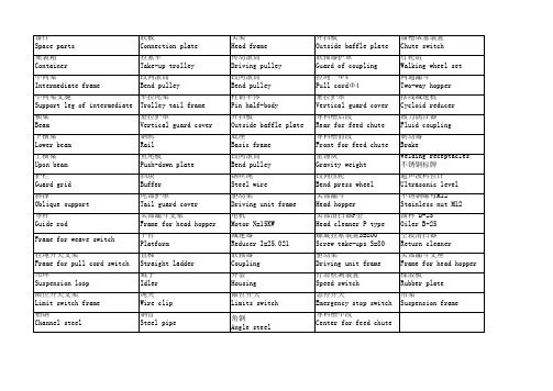
溜槽堵塞装置 Chute switch 行轮组 Walking wheel set 两通漏斗 Two-way hopper 摆线减速机 Cycloid reducer 液力偶合器 Fluid coupling 制动器 Brake Welding receptacles 不锈钢标牌 超声波料位计 Ultrasonic level 不锈钢螺母M12 Stainless nut M12 油杯 B-25 Oiler B-25 空段清扫器 Return cleaner 头部漏斗支座 Frame for head hopper 橡胶板 Rubber plate 吊架 Suspension frame
头架 Head frame 传动滚筒 Driving pulley 改向滚筒 Bend pulley 柱销半体 Pin half-body 外挡板 Outside baffle plate 底座 Basic frame 改向滚筒 Bend pulley 钢丝绳 Steel wire 驱动架 Driving unit frame 电机 Motor N=15KW 减速器 Reducer I=25.021 联轴器 Coupling 外套 Housing 限位开关 Limits switch 角钢 Angle steel
外挡板 Outside baffle plate 联轴器护罩 Guard of coupling 拉绳 Φ 4 Pull cordΦ 4 垂拉护罩 Vertical guard cover 导料槽后段 Rear for feed chute 导料槽前段 Front for feed chute 重锤块 Gravity weight 改向压轮 Bend press wheel 头部漏斗 Head hopper 头部清扫器P型 Head cleaner P type 螺旋拉紧装置S=800 Screw take-ups S=80 驱动架 Driving unit frame 打滑检测装置 Speed switch 急停开关 Emergency stop switch 导料槽中段 Center for feed cate 拉紧车 Take-up trolley 改向滚筒 Bend pulley 车拉尾架 Trolley tail frame 垂拉护罩 Vertical guard cover 钢轨 Rail 鱼尾板 Push-down plate 挡块 Buffer 尾部护罩 Tail guard cover 头部漏斗支架 Frame for head hopper 平台 Platform 直梯 Straight ladder 辊子 Idler 绳夹 Wire clip 钢管 Steel pipe
外文翻译-带式输送机
翻译部分英文原文1.1 The take type transports the characteristics and the application of the machineThe take type transports machine since 1795 was disheveled hair and clear,through the development of more than twocenturies,already drive electric power、metallurgy、coal、chemical engineering、mineral mountain、portetc.every trade adopts extensively.Especially the Industrial Revolution brings material,lately technical adoption for the third time lately and makes the take type transport the development of the machine to follow a new era.In now days ,whether appraise from carry、length、economy-effectiveness and so on.It can be the same train,automobile transport to match the situation as it stands,and become the first to the development of industries.The take type transports the characteristics of the machine:The structure is simple.Followed by belt conveyor drive pully to one drum,or idler roller components、drives、conveyors several large components.Only a dozen or more components,production can be standardized and may require portfolio assembly,the structure is very simple;Transport the material scope extensively.Conveyor belt with wear,corrosion resistance ,oil resistance,such as fire-retardant properties,and high-resistance,low temperature,may be required to produce,which will transport all kinds of stuff,block materials,chemicals,the Health clinker and concrete;Transport to have great capacity.V olume per hour from a few kilograms to several thousands of tons,but is uninterrupted deliveryThis is the train,the automobile conveyance is too far behind to catch up;The luck is apart from to grow.Single length of up to 10 kilometers an abroad,is very popular,in the middle reproduced without any points.Cross-countrily the take type transports machine to often use to rub to drive a way in the center,making to transport the restriction that the length is free from thebelt conveyer strength.It is strong to the circuit adaptability.Modern belt conveyor in laying cross-country,from the trough to tube-shaped,it can be horizontal and vertical plane tumed breaking the mold conveyor or not bend the restrictions,which will rely on mountain water,and walk along the terrain,can save a lot of a tunnel,bridge infrastructure investment;Pack to unload very convenient.Under the belt conveyor process needs,may at any point on the equipment and dump;Pipe conveyor as well.Can also pack,unload to anticipate on the return journey segment ,carry on anti-to conveyance;The credibility is high .As simple structure,moving parts light weight ,as long as the belt is not torn,with a life span of 10 years,metal components,as long as antirust good,for the past several decades is not a bad idea;The operation fee is cheap.Wear parts belt conveyor idlers and only roller,conveyor longevity,a high degree of automation,use of the staff is small,per km on average less than one,the consumption of oil and electricity rarely;Can consume low,the efficiency is high.Since moving parts as light weight,low void shipped in all non-continuous and continuous transport,Belt conveyor energy minimum,maximum efficiency;Maintain a fee little .Belt conveyor is the only moving parts and idler pulley,belt wear is very.Compare under,the train,automobile wears away a parts to want many,and replace to wear away a piece also more multifarious;On the other say,the take type transports the superiority of the machine already very obviously,it is the key equipments of the indispensability in the national economy .Moreover,Internet the realization has been greatly shortened the belt conveyor design,development,manufacture,sales cycles,make it more competitive.1.2 The take type transports the present condition and the development of the machineTake type’s transporting machine is the coal mine is the most ideal totransport an equipments efficiently and continuously,compared with other conveyance equipmentses have distance of transport long,the carrying capacity is big and continue to transport etc.advantage,and circulate credibility,be easy to the realization automation and concentrate to turn a control,particularly to high produce efficiently the mineral well,the take type transports the key equipments that the machine has become coal to mine the machine electricity integral whole to turn a technique and equips.Along with the our country is high to produe of mineral well efficiently now,the take type that is originally possessed’s transporting machine is a regardless main parameter to still circulate functions and all have already can’t satisfy a request,have to the long pull,high take soon,big carrying capacity,big power of large turn the direction development,and want improve and raise to circulate function, insure safe credibility.The take type that the our country production make transports the species,type of the machine more.In the”Enghth Five-Year Plan”period,the national one-stop “Nissan 10,000 tons fully mechanized equipment”projects,conveyor technology has-greatly improved,and mine with high power .The key to long-distance belt conveyor technology research and development of new products ,LU has made considerable progress.Such as the big cape long pull take type transport machine to become a set an equipments,high produce to work efficiently noodles fluently slot the flexible take type transport machine ,etc.all filled up local bland ,and transport machine to turn down the key technique to the take type and it main dollar the parts carried on the theories research and the product development,develop successfully variety soft start and make to move equip and take PLC as core of the programmable electricity control device,driving the system adoption to adjust soon type the liquid dint matches the machine and the planet wheel gear to decelerate a machine accidentally.The coal mine take type transports technical development trend of machine .The equipments is large to turn,the exaltation transport an ability:For adapt high produce efficiently intensive turn the demand of the production,the take type transports machine to transport an ability to want enlargement.Long-distance,high beltspeed,large-capacity,high-power future is the inecitable trend of development,as well as transport for the high-technology development direction.Transport quantity and raise to the 3000-4000 ts/h in the 10 as of aftertime also raise to the 4-6 ms/s soon,transport length to transport to the flexible take type confidential attain a 3000ms.For strength steel belt conveyor take longer to 5,000 m above single-driven power demand reached 1,000~1,500 kw,conveyor tensile strength reached 6,000 N/mm (steel cord)and 2500 N/mm (steel cord).By the coal mine well to descend agreeable slot particularly flexible transport a technical development,along with high produce efficiently continuously develop of the emergence and the coal science and technology of work the noodles,the original flexible take type transports machine,is a regardless main parameter,still circulate functions all hard adapt high produce efficiently a request of work the noodles,the coal mine needs main parameter urgently on the scene greater ,the technique is more advanced,function more dependable long pull ,big carrying capacity 、big power fluently slot the flexible take type transport machine ,transporting technical design level of machine by the exaltation our country take type,filling up local bland,near to and catch up the technique level of the international advanced industrial country.It contains seven of the key technologies:(1) belt conveyor dynamic analysis and control technology;(2)soft start with the power balance technology;(3)Intermediate Driver;(4)automatic tensioning technology .(5)new lifetime high technology high-speed roller;(6)rapid shift from the tail;(7)with efficient storage technology.Raise 1 dollar parts function and credibicity :The equipments switch on rate of high and low mainly be decided by the function and the credibility of 1 dollar parts.In addition to further improving and enhancing the existing yuan parts of the performance and reliability,we will continue to research and development of new technologies and metadata components,such as high-performance technical controllable soft start,Dynamic Analysis and Monitoring Technology,and efficient storage devices with rapid shift from the tail,high-speed roller,belt conveyor so that the performance can be further raised.Extend function ,a machine uses to turn much:Expan a luck a person,carry to anticipate or double to conveyance etc.function,attain a machine to use much,make it the exertive and biddest economic performance.Develop a special type a take type to transport machine,if the flection take type transports the machine,big cape or perpend cularity to promote to transport machine etc.The big cape take type transports the extreme limit that the machine broke the last luck cape 25°s,expand,mine for the coal mine and the main and inclined well transported an equipments to choose a type to develop a new path,also transporting the equipments that the system changed an extension to provide economy efficiently for the current inclined well,to raise a yield and decline low cost have important meaning.The level take type transports machine to have amplitude in the our country mineral mountain the production of applied foregroune,especially in the coal mine.My more inclind seam,16~25° tilt seam exist in large numbers.The take type transports the function success to used for the bottom of the well,since can reduce tunnel to expand the quantity and equipments.中文译文1.1带式输送机的的特点与应用带式输送机自1795年被发明以来,经过两个多世纪的发展,已被电力、冶金、煤炭、化工、矿山、港口等各行各业广泛采用,特别是第三次工业革命带来了新材料、新技术的采用使带式输送机的发展步入了一个新纪元。
带式输送机英文文献翻译
原文Transporting machine to press the operation way can is divided into:1:The leather belt type transports machine 2:Is spiral to transport machine 3:The Dou type promotes machine 4:The roller transports machine 5:Calculate to transport machine 6:The plank chain transports machine 7:The net takes to transport machine 8:The chain transports machine.1.ParameterIs general according to various condition of request, material shipping point that the material transports system, relevant of the production craft process and material of characteristic etc. to make sure each main parameter.①Transport ability:The ability of transporting the transporting of machine means unit for time inside transport of material quantity.While transporting to spread a form material, with the quality or physical volume calculation that the per hour transports a material;At transport into a piece product, with the number of items calculation that the per hour transports.②Transport speed:The exaltation transports speed to improve the ability of transporting.When being making to lead a piece by belt conveyer and transporting length was more big, transport speed to gradually enlarge.But the take type ofhigh-speed operation transports machine to need to notice vibration, Zao voice and start and make etc. problem.For use chain as lead a piece of transport machine, transporting the speed should not lead greatly, in order to prevent the aggrandizement power carry a lotus.Carry on transporting of craft operation machine at the same time, transporting the speed should press to produce a craft to request an assurance.③Reach a size:Transport reaching of machine a size to include belt conveyer width, lath width and anticipate Dou capacity, piping diameter and container all of etc.s.Thesereach a sizes to all directly influence to transport machine of transport ability.④Transport length and Qing Cape:Transport circuit length and Qing Cape size to directly influence the total resistance of transporting the machine and need of power. 2.Transport a machine the spot application wayConstitute to carry on explaining in detail from the take type machine system first:Leather belt's transporting machine is to spread a form material to transport and pack to unload an equipments most importantly, can extensively used for the mineral mountain, metallurgy, building materials, chemical engineering, electric power, industrial realms like food processing,etc, in the coal mine, metal mineral, the steel business enterprise, port, grounds like cement works,etc a great deal of application that can see skin machine, transporting the machine can not only complete to spread a transporting of form material, but also can transport into a piece material, but basis use location, work environment, transport the dissimilarity of material category, will also have bigger difference in its design and the application;Modernization of transport the machine system has higher request to the dust palliative, is this, in each the device that transfer place and establish and sprinkle water and gather a dust, transport machine and follow line in the tape will establish and defend a breeze cover or block an aerofoil, system from list the machine constitute of, to work in the whole machine system of operate and fix to say, want and have a foothold and divide the single machine of the tube at oneself, and want to understand mutual contact between systems, list machine again is constitute to°from many partses, only work well the daily maintenance of each parts maintains and makes it is placed in good work status so as to ensure the safe movement of equipments;We generally will transport the use place, work environment of machine according to the take type, technique function and transport material category to wait variousdissimilarity with satisfy various forms of homework work condition, in addition to in addition to transporting machine, the in general use leather belt of more adoption also various special kind tapes of new structure transport machine and have a mainly having of the representative among them:Big Qing Cape take type machine, deep slot take type machine and press take type machine, take care of the form take type, the air cushion take type, the flat surface turn take type, the line friction type, wave-like in shape the belt conveyer type blocking a side transport machine etc. and carry on a thin method for turning and canning exist various classifications and make following introduction now: Press the use classification, there is in general use ambulation type, under the well choice type, the strip mine is used a fixed type, special kind structure type, can move a place type and transport machine, load machine appropriation redistribution function type, the big Qing Cape type transports machine etc., generally speaking transport machine inside the short distance factory can complete level, up the luck or bottom carries, canning go against the wood grain type leather belt machine can be used for double to transport a material, hang arm machine usually install anticipate on board in the heap, and can turn round, line up the function of soil or cloth by realization, but Gao Jia Ji propped up by in the door usually match with other spread and anticipate and handle an equipments common use, for example give or get an electric shock and constuct a medium application in water, can install standard in the center frame, the machine's mounting places on the track Zhen, easy to move and place;Press the category of transporting the material to categorize, have the generally lax material is used of, the strong and tough material is used of and list piece the leather belt used in material transport machine etc. and press the rubber conveyance takes a loading segment of position to categorize, include a leather belt loading segment at top of and loading segment at underneath of and at the same time loading segment at upunderneath of double to transport machine three, the use double can distinguish to transporting machine at up branch and bottom branch transport a material, but for keeping material contact noodles don't produce a change and need to bring in to go to the rubber to be periodically inside out.3.CategorizeTransporting machine generally and pressing already didn't lead piece to carry on a classification and had to lead a transporting of piece machine to generally include to lead a piece, loading to reach a piece, drive device, bring to the stretch device and change to accept an etc. to the device and.Lead a piece to in order to deliver to lead dint, can adopt belt conveyer and lead chain or steel wire rope;The loading reaches a piece to in order to accept to put a material and has already anticipated Dou and bracket or mourns to have...etc.;Drive device to transport machine with the power, generally from electric motor, decelerate a machine and make machine(stop a machine) etc. to constitute;Bring to the stretch to equip to generally have the Luo pole the type and heavy hammer type 2 kind, can make to lead a piece to keep certain tension and hang a degree, transport machine by assurance normal operation;Pay to accept a piece to in order to accept to give to lead piece or loading to reach a piece, can adopt to give Gun and roll an etc..Having the structure characteristics that lead the transporting of piece machine is:Be delivered a material and pack reaching with the loading leading a link together inside the piece, or directly pack in leading a piece(is like belt conveyer), led a piece to once round each roller or the chain round beginning and end and connect with each other, formation include and deliver a having of material carry branch and don't deliver a material of have never carried shutting of branch and match wreath road, make use of lead continuous sport of piece and transport a material.This type ofly transporting model is numerous, there is mainly a take type transporting a machine, plank type andtransporting a machine, small car type and transporting machine, escalator, automatic sidewalk, paring off plank and transporting machine, covering up and paring off plank and transporting a machine, Dou type and transporting a machine, Dou type and promoting machine and hanging and transporting machine and build on stilts a cableway...etc..The structure that didn't lead transporting of piece machine constitutes each not same, use to the work of transporting the material to reach a piece as well not same.Their structure characteristicses are:Make use of a work to reach a revolving of piece to exercise or the back and forth exercise, or make use of lie quality to make the material transport forward in the fluxion in the piping.For example, the Gun son transports the work of machine to reach the piece as a series of Gun son, the Gun son makes to revolve sport to transport a material;Is spiral to transport the work of machine to reach a piece for spiral, helix at anticipate and make to revolve sport in the slot with follow anticipate slot to push to send a material;The vibration transports the work of machine to reach piece in order to anticipate slot, anticipate slot to make back and forth sport with transport Be placed to among them of material etc..Install(1)The fixed type transports machine should by rule gearing method gearing at fix of foundation up.The ambulation type transports machine formally before circulating and should live wheel with the wedge Xie or uses to make a machine to stop.So as not to take place to take a stroll in the work, there is the passage that many sets , between machine and machine, there shoulded be one meter between wall and machine while transporting a parallel homework of machine.(2)The beard checks an each operation part, tape to take to button up to equip with loading before using whether normal, whether protection equipments is well-found.Thetape rises a tight degree beard before starting the adjustment is to suitable extent.(3)Leather belt's transporting machine should get empty to carry a start.Waiting to revolve normal rear can go into to anticipate.Drive after forbiding to go into first to anticipate.(4)There are few set that when transport machine to establish to circulate should from unload to anticipate to carry a beginning, the sequence starts.After revolving as usual all, the square can go into to anticipate.(5)Appear in the movement when the tape runs to be partial to a phenomenon should park the car adjustment, can not force an use, so as not to wear away edge and increment burden.(6)Work environment and be sent material temperature not to must be higher than50 ℃ and be lower than-10 ℃ .Can not transport the material of having sour alkaline oil and organic melting agent composition.(7)Forbid pedestrian or multiply by a person on the belt conveyer.(8)Have to stop going into first to anticipate before parking the car, wait leather belt up save to anticipate to unload to the utmost a square can park the car.(9)Transporting the machine electric motor has to insulate good.The ambulation type transports machine electric cable to pull and drag along indiscriminately.The dynamoelectric confidential credibility connects ground.(10)The leather belt beats slippery strictly forbid to by hand pull leather belt, so as not to take place trouble.5.Adjust to try(1) Each equipments with meticulous care adjusts to try to transport machine after installing and satisfies a drawing request.(2) Each deceleration machine exercises parts to add to note to correspond lubricant.(3) The gearing after transporting machine to attain to request each single set equipments carries on beginning to work to make run-in, and knot to put together to adjust to try to transport machine to satisfy an operative request.(4) Adjust to try the electricity part of transporting the machine.Include to connect adjusting of line and action to try to the normal regulations electricity, make the equipments have good function, attain the function and status of design.6.Transport machine to block knothole 2 kinds of boring crafts(1)Blow up boring:The material after the irradiation of continuous laser and centrally forms one cave pit, then from and laser beam the coaxial oxygen flow to clean meltdown material and form one bore very quickly.The size of general bore is as thick relevant as plank, blow up to bore hole the average diameter as thick plank half, therefore blow up to bore hole bore path bigger to thicker plank, and not circle, should not in requesting higher spare parts use(if the petroleum Shai sews a tube), can be used for a waste up.In addition because of bore hole use of oxygen pressure with incise homology, splash a little bit greatly.(2)Pulse boring:The pulse laser that adopts high peak value power makes a little amount material melt or vaporizes, in common use air or nitrogen spirit are to lend support to air and oxidize to make bore expand because of putting heat by decrease, the air pressure more incises of the oxygen pressure is small.The particle jet with small creation of each pulse laser gradually goes deep into, therefore slab boring time takes several seconds.Once bore hole completion, immediately change assistance air into oxygen to carry on incising.Boring hole diameter like this is smaller, its boring quality is better than to blow up boring.Not only should have higher exportation power for the laser machine used by this;The time and space characteristic that more important time ties, therefore the general crosscurrent carbon dioxide laser machine can not adapt to therequest that the laser incises.In addition the pulse bores hole to also have the more dependable spirit road the control system to carry out cutting over of air category, air pressure and bore hole a horary control.译文:输送机按运作方式可以分为:1:皮带式输送机2:螺旋输送机3:斗式提升机4:滚筒输送机5:计量输送机6:板链输送机7:网带输送机8:链条输送机。
带式输送机技术的最新发展外文文献翻译、中英文翻译、外文翻译

附录Ⅰ英文文献翻译附录A带式输送机技术的最新发展M. A. AlspaughOverland Conveyor Co., Inc.MINExpo 2004拉斯维加斯, 内华达州,美国,2004.9.27摘要粒状材料运输要求带式输送机具有更远的输送距离、更复杂的输送路线和更大的输送量。
为了适应社会的发展,输送机需要在系统设计、系统分析、数值仿真领域向更高层次发展。
传统水平曲线和现代中间驱动的应用改变和扩大了带式输送机发展的可能性。
本文回顾了为保证输送机的可靠性和可用性而运用数字工具的一些复杂带式输送机。
前言虽然这篇文章的标题表明在皮带输送机技术中将提出“新”发展,但是提到的大多思想和方法都已存在很长时间了。
我们不怀疑被提出一些部件或想法将是“新”的对你们大部分人来说。
所谓的“新”就是利用成熟的技术和部件组成特别的、复杂的系统;“新”就是利用系统设计工具和方法,汇集一些部件组成独特的输送机系统,并解决大量粒状原料的装卸问题;“新”就是在第一次系统试验(委任)之前利用日益成熟的计算机技术进行准确节能计算机模拟。
同样,本文的重点是特定复杂系统设计及满足长距离输送的要求。
这四个具体课题将覆盖:1、托辊阻力2、节能3、动力分散4、分析与仿真节能减小设备整体电力消费是所有项目的一个重要方面,皮带输送机是也不例外。
虽然与其他运输方法比较皮带输送机总是运输大吨位高效率的手段,但是减少带式输送机的功率消耗的方法还是很多的。
皮带输送机的主要阻力组成部分有:a.托辊阻力b.托辊与皮带的摩擦力c.材料或输送带弯曲下垂引起的阻力这些阻力加上一些混杂阻力组成输送材料所需的力。
1在一台输送长度400米的典型短距离输送机中,力可以分为如图1所示的几个部分,图中可以看出提升力所占比例最大,而阻力还是占绝大部分。
图1在高倾斜输送带中如矿用露天倾斜输送带,所受力可分解为图2所示的几个部分,其中提升力仍占巨大比例。
由于重力是无法避免的,因此没有好的方法减少倾斜式输送机所受力。
- 1、下载文档前请自行甄别文档内容的完整性,平台不提供额外的编辑、内容补充、找答案等附加服务。
- 2、"仅部分预览"的文档,不可在线预览部分如存在完整性等问题,可反馈申请退款(可完整预览的文档不适用该条件!)。
- 3、如文档侵犯您的权益,请联系客服反馈,我们会尽快为您处理(人工客服工作时间:9:00-18:30)。
附录A带式输送机技术的最新发展摘要粒状材料运输要求带式输送机具有更远的输送距离、更复杂的输送路线和更大的输送量。
为了适应社会的发展,输送机需要在系统设计、系统分析、数值仿真领域向更高层次发展。
传统水平曲线和现代中间驱动的应用改变和扩大了带式输送机发展的可能性。
本文回顾了为保证输送机的可靠性和可用性而运用数字工具的一些复杂带式输送机。
前言虽然这篇文章的标题表明在皮带输送机技术中将提出“新”发展,但是提到的大多思想和方法都已存在很长时间了。
我们不怀疑被提出一些部件或想法将是“新”的对你们大部分人来说。
所谓的“新”就是利用成熟的技术和部件组成特别的、复杂的系统;“新”就是利用系统设计工具和方法,汇集一些部件组成独特的输送机系统,并解决大量粒状原料的装卸问题;“新”就是在第一次系统试验(委任)之前利用日益成熟的计算机技术进行准确节能计算机模拟。
同样,本文的重点是特定复杂系统设计及满足长距离输送的要求。
这四个具体课题将覆盖:●托辊阻力●节能●动力分散●分析与仿真节能减小设备整体电力消费是所有项目的一个重要方面,皮带输送机是也不例外。
虽然与其他运输方法比较皮带输送机总是运输大吨位高效率的手段,但是减少带式输送机的功率消耗的方法还是很多的。
皮带输送机的主要阻力组成部分有:●托辊阻力●托辊与皮带的摩擦力●材料或输送带弯曲下垂引起的阻力●重力这些阻力加上一些混杂阻力组成输送材料所需的力。
1在一台输送长度400米的典型短距离输送机中,力可以分为如图1所示的几个部分,图中可以看出提升力所占比例最大,而阻力还是占绝大部分。
图1在高倾斜输送带中如矿用露天倾斜输送带,所受力可分解为图2所示的几个部分,其中提升力仍占巨大比例。
由于重力是无法避免的,因此没有好的方法减少倾斜式输送机所受力。
图 2但是在长距离陆上输送机中,所受力更趋向图3所示的几个部分,不难看出摩擦力几乎是所受力的全部。
这种情况下考虑主要受力才是最重要的。
图 3力量演算具体是超出本文的范围之外,但是值得一提的是,在过去几年对所有四个区域橡胶凹进、对准线和材料或者传送带弯曲等方面的重要研究都在进行。
并且,虽然在处理每特定区域时大家有不同意见,通常对整体项目经济是必要和重要的是被大家被接受的。
在2004个SME年会上,MAN Takraf的Walter Kung介绍了题为“Henderson粗糙矿石输送系统—回顾组装、起动和操作”2。
这个项目在1999年12月被实施并且包括一个24公里(3飞行)陆上转达的系统替换地下矿碾碎路轨货车使用系统。
图4 - Henderson PC2到PC3调动站最长的传动机在这个系统(PC2)是16.28公里长与475m升距。
最重要的系统事实是提供的功率(4000千瓦在1783 mtph 和4.6 m/s)的50% 被要求用来转动一条空载的带子,因此输送系统的效率是很重要的。
需密切注意托辊、传送带盖子橡胶和对准线。
用文件说明有关的效率的差别是的一种方法,使用"相等的摩擦系数f"的22101标准定义作为比较主要抵抗的总数的另一种方法。
过去,象这样典型输送装置的综合设计噪音系数大约是0.016f。
MAN Takraf正估计他们对力的敏感达到到0.011的f,超过30%的削减。
这在减少设备建造成本上做出了重大贡献。
通过六次的实际动态测量显示价值是0.0075,甚至比期望值低30%。
Kung先生强调这将在仅仅用电费用一项上每年减少费用10万美元。
线路优化图5 –中国天津水平适应性当然最高效率的材料运输方式是从一点到下一点的直线输送。
但是,由于自然和认为障碍的存在,我们在长距离输送过程中直接直线输送的可能性越来越小。
第一台水平弯曲输送机已在很多年前安装使用,但它今天似乎关于安装的每台陆上传动机在方向至少有一个水平变化。
并且今天的技术允许设计师相对地容易地调整这些曲线。
图5和图6显示的是把煤从蕴藏地运输到中国天津港口管理处的陆上输送装置。
这套运输机由E.J. O’Donovan & Associates设计,由Continental Conveyor Ltd of Australia 公司承建,长达9千米的输送距离4台1500千万电机驱动运输能力达6000 mtph 。
图6 –天津输送线平面图Wyodak矿位于美国怀俄明州粉河流域,是记录中最古老的连续经营的煤矿,自1923年运营至今。
它一般运用坡面(图7)从新的矿坑到装置756m (2,482 ft)与700m (2,300 ft)水平的半径。
这表明由于水平轮的应用输送机不需要设计太长3。
图7- Wyodak 煤矿隧道式如通过没有水平曲线线路,另一项产业,隧道挖掘,就不能使用带式输送机了。
隧道就想象废水和运输那样的基础设施在全世界有。
移动隧道粪肥的最有效率的方法通过把推进的输送装置和隧道机器的后部连结起来。
但是这些隧道极少是直的。
这里有一个例子,西班牙10.9m直径隧道的在巴塞罗那之下作为地铁(火车)引伸项目一部分。
大陆输送机机有限公司安装了前 4.7km传动机如图8和9所显示和最近接受合同安装第二台8.39公里输送机。
图8- 巴塞罗那隧道平面图图9- 隧道内部另一个例子,肯珀建设边境时,建设一个直径3.6米长6.18公里的隧道作为大都市圣路易斯的下水道区。
鲍姆加特纳隧道(图10)将装有600毫米宽的用4个中间运动用带子系住的6.1 公里输送装置。
图10- 鲍姆加特纳隧道平面图管状输送装置如果常规输送机不能满足必须的输送要求,带式输送机的一种管状输送机会是不错的选择。
图11- 管状输送装置它最简单的描述,管状输送机就是由管状橡胶管和空转辊组成。
这种设计具有其他传送方式的优点,更有自己的特点。
托辊可以在各个方向传力允许更复杂的曲线输送。
这些曲线可以是水平或垂直或混合形式。
这样的输送机输送带与托辊之间的重力和摩擦力保证原料在输送管道内。
Figure 12管状输送机的另一个好处可以输送粉状原料并且可以减少溢出浪费,因为材料是在管道内部。
一个典型的例子是环境效益和适应性特好的美国犹他州地平线矿(图12)。
这个长3.38公里的管状输送机由ThyssenKrupp Robins 安装通过一个国家森林并且横断了22个水平段和45个垂直段。
Metso 绳索输送机另一种由常规衍变来的是Mesto 绳索输送机(MRC),通常以缆绳传送带著名。
这个产品以长途输送著名,在距澳大利亚30.4公里的沃斯利铝土矿上应用的输送带是最长的单个飞行输送机。
在钢绳输送机上,驱动装置和运载媒介是分离的。
图13 - MRC-平直的部分这种驱动与输送装置的分离允许输送有小半径的水平弯曲,这种设计优于根距张紧力和地势的传统设计。
图14MRC与常规输送机水平曲线的不同图15- 位于加拿大Line Creek的MRC图15显示的是位于加拿大Line Creek河畔的一条长10.4公里水平半径430米的缆绳输送带立式输送装置有时材料需要被提升或下降而常规输送机被限制在16—18度附近的倾斜角度内。
但是带式输送机的非传统衍变不管是在增加角度还是平直方面都是相当成功的。
大角度输送机第一台大角度输送机由Continental Conveyor & Equipment Co.公司生产,非常利用常规输送机零部件(图16)构成。
当原料在两条带子之间输送时,被称为三明治输送装置。
图16Continental 公司的第100套大倾角输送装置采用独特的可平移式设计,作为Mexican de Canenea的堆过滤垫(图17)。
Figure 17垂直式输送装置第二种立式输送装置展现的是一种非常规的带式装置,它可以实现垂直输送(图18)。
这种Mesto 垂直输送机,2001年由Frontier Kemper 安装在白县煤矿Pattiki 2矿(图19),将煤由273米深的矿井输出并达到1,818 mtph的输送能力。
图18图19- Pattiki 2矿动力分散在最近过去的一段时间里,一种最有趣的发展是电力沿输送道路的分配。
看到输送机驱动装置安装在收尾末端,让尾端驱动完成输送带的拉紧输送工作。
但是现在的发展观念是把驱动安装在任何需要的位置。
在带式输送机上多个位置安装动力源的想法已经存在很长一段时间了。
第一次应用是1974年安装在美国Kaiser煤矿。
紧接着是在地下煤矿中得到应用,而且长臂开采法也越来越体现它的优越性。
采矿设备的效率和能力也得到巨大改善。
矿工们也开始寻找大的矿区从而减少移动大型采矿设备的次数及时间。
矿井宽度和矿井分格长度都得到增加。
当矿井分格长度增加后,输送问题开始出现。
接近4-5千米的输送长度所需要的电力和输送带的强度比以前地下煤矿需要的大很多。
问题是大号的高电力驱动装置安装及移动困难。
虽然胶带技术能够满足胶带所需强度要求,它意味着需要比钢铁更重要的强度及加硫处理。
由于长臂开采法的盘区传动机经常推进和后退,矿工需要经常增加或取消滚筒的正传与逆转。
而且硫化结合需要长期维护以保证强度,因而失去的产品生产时间在一个完全盘区中是很严重的。
现在需要超过风险,并且中间驱动的应用限制了输送带的伸长及张紧这样就允许纤维胶带在长距离输送机中应用。
现今,中间驱动技术被很好的接受并越来越广泛的应用于地下煤矿中。
世界范围内的许多矿把这项技术整合到现在和未来矿业计划当中来增加他们的整体采矿效率和效益6。
表20所示的张紧图显示了中间驱动的重大好处。
这种平面前驱的输送机有简单的皮带张力分布如黑色线条所示。
虽然平均皮带张力在每个周期期间只约为最大值的40%,但必须围绕最大估量值附近。
黑色线条的急剧回落表示顶头滑轮要求的总扭矩和力量来启动输送机。
将受力分解到两个地点(红线),当总功率基本相同的情况下,皮带张力差不多减少40%。
因此更小的输送带和更小的电源组可以得到运用。
为了进一步扩展这种方式,增加第二中间驱动(绿线),皮带峰顶张力进一步下降。
隧道产业也迅速采用这种技术并且把这项技术提高到更好的水平,更复杂更先进。
但挖隧道最需要的是水平曲线的进步。
通过中间驱动(图21)的一种应用例如Baumgartner 隧道如前图10所描述,皮带张紧力可以通过在重要的地点安装战略驱动来控制,从而实现输送带的小曲线换向。
图20图21在图22中,绿色投影区域代表弯曲结构的地点。
蓝色线条代表输送带运载面,粉红色线条代表输送带返回面。
可以发现在弯曲半径最小750米时输送带运载面和返回面所受张紧力均达到最小。
图22尽管到目前为止,这项技术陆上输送机中没有广泛的应用,一些倾向于水平曲线的技术却得到发展。
图23显示了南美洲的一条长8.5千米硬岩层输送带,它需要4个中间驱动来实现4段2000米半径的曲线转向。
Figure 23- 平面图图24显示在弯曲段有与没有驱动时输送带的张紧力比较。