远东M系列阀组使用说明书
海尔VQ400M系列类A安全组合阀门产品说明书

VQ400M SERIESCLASS “A” COMBINATION VALVESPRODUCT HANDBOOKAPPLICATIONFigure 1 VQ420M & VQ425MFigure 2 VQ440M & VQ450MThe VQ400M Series class “A” safety combination valves are used for control and regulation of gaseous fluids in gas power burners, atmospheric gas boilers, melting furnaces, incinerators and other gas consuming appliances.The VQ400M offers flexibility to mount accessories like valve-position indicator, pressure indication switches, vent-valves or by-pass valves at several positions at the gas valve, whenever, wherever. These combination valves are available in two body sizes:∙ Small modelo VQ420 o VQ425∙ Large modelo VQ440 o VQ450All models are connected at suitable sized gas pipes by flange kits which can be ordered separately in several sizes.CONTENTSVQ400M SERIES (1)CLASS “A” COMBINATION VALVES (1)APPLICATION (1)Contents (2)FEATURES (2)DESCRIPTION (3)SPECIFICATION (3)Models (3)Dimensions (3)Pipe sizes (4)Capacity (4)Connections (4)Torsion and bending stress (4)Supply voltages (4)Electrical equipment (4)Electrical connections (5)Ambient temperature range (5)Coil insulation solenoid valves (5)Enclosure (5)Body material (5)Closing spring (5)Valve plunger (5)Seals and gaskets (5)Power consumption (5)PERFORMANCE CHARACTERISTICS (6)Opening time (6)Closing time (6)Maximum working frequency (6)Duty cycle (6)Operational voltage range (6)Designed life time (6)CAPACITY CURVES (7)INSTALLATION (8)IMPORTANT (8)WARNING (8)Maintenance and service (8)Mounting position (8)Mounting location (8)Main gas connection flanged valves (9)WARNING! (9)Electrical connection (9)WARNING (9)Wiring (9)ADJUSTMENTS AND FINAL CHECKOUT (11)CAUTION (11)2nd main valve fast opening (11)2nd main valve slow opening (11)IMPORTANT (11)Final checkout of the installation (12)OPTION INSTALLATION (13)WARNING (13)CONSTRUCTION AND WORKING PRINCIPLES (13)ORDERING INFORMATION (14)NOTE (14)Replacement of parts (15)Warning (15)Recommended accessories (15)APPROVALS (17)Declaration of Conformity ........... Error! Bookmark not defined.FEATURES∙Class “A” safety combination valve forcontrol of gaseous fluids in gas consumingappliances in accordance with internationalstandards.∙Main body with two gas valves with single seat.∙Possibility of installing internal by-pass valve to achieve high-low flame control.∙Possibility of installing internal or external pilot valve.∙Possibility of installing vent valve.∙Possibility of installing flanged minimum and maximum pressure switches.∙Possibility of installing valve ProvingSystem (VPS).∙Possibility of mounting Closed Position Indication switch (CPI) at bottom of safetyvalve V1 and / or valve V2.∙Closing time: < 1 second.∙ Coils field replaceable.∙Coils suitable for permanent energizing.∙Fine mesh screen between inlet flange and main body (optional).∙Various pressure tap points at main body available∙Second main valve, either with adjustable flow regulator (fast), or characterizedopening mechanism (slow) with adjustablemaximum flow rate and step pressure.∙Rectifier boards field replaceable.∙PG11 cable strain relief standard atVQ400M.∙Plug connector according to ISO 4400 / DIN EN 175301-803 optional for VQ400M.DESCRIPTIONThe VQ400M Series combination valves are suitable for the control of gaseous fluids in gas consuming appliances according to international standards.The VQ400M Series combination valves meet the class “A” specification according EN161. TheVQ400M Series combination valves can be ordered with straight flanged pipe connection from 1/2 " up to 2". The VQ400M Series combination valves are standard equipped with two safety valves V1 andV2. The first valve (V1) is always fast opening. The second valve (V2) can be either fast or slow opening.∙Standard the second valve (V2) is supplied with throttle screw (fast opening with flowregulation).∙Optionally the second valve (V2) can be ordered with slow opening device (with flowregulation and adjustable opening).∙Optionally the second valve (V2) can be ordered fast open, without any regulationdevice.SPECIFICATIONThe specifications described in this chapter are related to the main gas valves.ModelsModels can be ordered according order specification numbering which is shownin Figure .15For an overview of all known combinations see surveys:∙ 50040300∙ 50040301 (Accessories) The VQ400M series combination valves areavailable in two body sizes:∙ Small modelo VQ420Mo VQ425M∙ Large modelo VQ440Mo VQ450MAll models are connected at suitable sized gaspipes by flange kits which have to be orderedseparately.DimensionsMain dimensions of the models are given atinstallation drawings:Table 1 Overview of installation drawings.Model Installationdrawing VQ420M INST0171VQ425M INST0172VQ440M INST0169VQ450M INST0170 Installation drawings are available in Honeywell documentation centre “HotDocs” and can besupplied digitally on request through Honeywellsales representative.Pipe sizesFor connecting with several pipe sizes it is recommended to mount Honeywell flange kits which can be ordered separately as indicated below.Table 2 Overview of recommended pipe sizes.Gas valve Recommended pipe size OptionVQ420M ½” 1 VQ420M ¾” 2 VQ425M 1”VQ440M 1¼” 1 VQ440M 1½” 2 VQ450M 2” Recommended flanges for each model to be mounted are given in table 3 and table 4. CapacityMain body: see capacity curves at Figure . Maximum operating pressure is 360 mbar for all models∙ 360 mbaro VQ420Mo VQ425Mo VQ440Mo VQ450M ConnectionsAs shown in the figure below, VQ400M is provided with plugs and flanges giving flexibility to customize this combination valve with Honeywell accessories.Figure 3 Interfaces for possible accessoriesTorsion and bending stressPipe connections meet group 2 according to EN161 requirements.Supply voltagesVQ400 M series can be ordered for line voltage: ∙230 Vac, 50/60 Hz∙115 Vac, 50/60 Hz∙120 Vac, 50/60 HzElectrical equipmentAC rectified coils with separated rectifier inside the cover.Plugs for mounting:∙pressure tap∙Valve provingsystem∙Pressure switchesPlugs for connecting:∙By pass valve∙Internal or externalpilot valve∙Vent valveFlange connection V2In the bottom plate twoplugs are available formounting ClosedOutlet flange Inlet flangeFlange connection V1Plug for mountingpressure tapElectrical connectionsVQ400M: standard plug connection accordingPG11 on main gas valves and additional valves. Optional: three pin plug connector (…DIN plug“) on main gas valves and additional valves.Ambient temperature rangeVQ400M is designed to operate in ambient temperature levels between: -15 ... 60 °CCoil insulation solenoid valves Insulation material is specified according class F. EnclosureIP54 in combination with PG11 connection.IP65 in combination with DIN-plug connection.Body materialAluminum alloy die cast body.Closing springAISI 302 steelValve plungerChrome plated Fe 360B steel sliding on anti-friction bearing.Seals and gasketsHydrocarbon resistant NBR rubber type Power consumptionHoneywell provides VQ400M with coils that suit demands of specified inlet pressure levels. An overview of power consumption for different applications is given in the table below.Table 3 Power consumption of each VQ400M main valve for360 mbar applications.115V120V230VVQ420M 16,5 18 15VQ425M 23,9 26,1 21,1VQ440M 52 56,7 46,5VQ450M- - 61PERFORMANCE CHARACTERISTICSOpening timeThe first valve (V1) opens in less than 1 second.The second valve (V2) can be either a fast opening valve which opens in less than 1 second or a characterized opening valve which is adjustable from 1 up to 30 seconds, at rated capacity.The opening characteristic is factory set at approximately 6 seconds at the following conditions:∙measured at 80 % of rated capacity∙30 mbar supply pressure∙ nominal voltage∙ 20 °C∙2,5 mbar pressure drop∙no step pressureDue to the influence of ambient temperature (-15 ...60 °C) the adjusted opening time of 6 seconds measured at 80% of adjusted flow rate can vary +/- 4 seconds.Closing timeLess than 1 second for both valves. Maximum working frequencyVQ400M is equipped for maximal working frequency of one cycle per minute.Duty cycleCoils are suitable for permanent energizing. Operational voltage rangeThe combination gas valve will function satisfactory between 85% and 110% of the rated voltage.Designed life timeOverview of designed life time is given in the table below.Table 4 Number of cycles per model.Model Number of cyclesVQ420MA 500.000VQ425MA 500.000VQ440MA 300.000VQ450MA 300.000CAPACITY CURVESFor comparison an overview of specified capacity of VQ400M is shown in table 5. Table 5 Overview of reference capacity in m3/h air at ∆p = 2.5 mbar.Gas valve Flange size Pipe size Flow capacityVQ420MA DN15 ½” -VQ420MA DN20 ¾” 8VQ425MA DN25 1” 11¼” 25VQ440MA DN32 1½” 31VQ440MA DN40 1VQ450MA DN50 2” 40In figure 4 a broader range of specified capacity for VQ400M is shown in curves.Figure 4 Capacity curve for VQ400M Series class …A” combination valves.INSTALLATIONIMPORTANT1. Read these instructions carefully. Failure tofollow the instructions could damage theproduct or cause a hazardous condition.2. Check the ratings given in the instructionsand on the product to make sure theproduct is suitable for your application.3. The installation has to be carried out byqualified personnel only.4. Carry out a thorough checkout wheninstallation is completed.WARNING∙Turn off gas supply before installation.∙Disconnect power supply to the valveactuator before beginning the installation toprevent electrical shock and damage to theequipment.∙Do not remove the seal over valve inlet and outlet until ready to connect piping.∙The valve must be installed so that the arrow on the valve points in the direction ofthe gas flow (gas pressure helps to closethe valve). Maintenance and serviceThe designed lifetime* of this product is 10 years, based on date code, according to:a) the standard EN 126b) the table on designed lifetime as stated onthe Afecor website /We cannot assume that the product can be safely used beyond the mentioned designed lifetime. This lifetime is based on use of the control according manufacturer’s instructions.Regular inspection of the control by authorized personnel in accordance with guidelines of the appliance manufacturer is required.After reaching the designed lifetime the product has to be replaced by authorized personnel.Note: * Warranty as opposed to designed lifetime is described in the delivery terms.Mounting positionThe gas valve can be mounted in vertical position with the coils at top side. The gas valve can be mounted plus or minus 90 degrees from the vertical.Mounting locationThe distance between the gas valve and thewall/ground must be at least 30 mm.Main gas connection flanged valves1. Take care that dirt does not enter the gasvalve during handling.2. Remove the flanges from the valve.3. Use a sound taper fitting with threadaccording to ISO 7-1 or new, properlyreamed pipe, free from swarf.4. Apply a moderate amount of good qualitythread compound to the pipe for fitting only;leaving the two end threads bare, PTFEtape may be used as an alternative.5. Screw the flanges onto the pipes.6. Ensure that inlet and outlet flanges are inline and separated from each other enoughto allow the valve to be mounted betweenthem without damaging the gasket.7. Place gasket. If necessary grease it slightlyto keep it in place.8. Mount gas valve between flanges using thebolts for each flange.9. Complete the electrical connections asinstructed in the electrical connectionsection.WARNING!Tightness test after installation∙Spray all pipe connections and gaskets with a good quality gas leak detectionspray.∙Start the appliance and check for bubbles.If a leak is found in a pipe connection,remake the joint. A gasket leak can usuallybe stopped by tightening the mountingscrews, otherwise, replace the gas valve. Electrical connectionWARNING∙Switch off power supply before making electrical connections.∙All wiring must comply with local codes, ordinances and regulations.Use lead wire which can withstand 105 °C ambient. The electric ON/OFF operator is provided with a terminal block for electrical connections.Wiring PG11Small models VQ420M-VQ425MRemove screws (A).Take off protective cover lids and gaskets (B). Take off plugs Pg11 from holes (Figure 5):(K) and (N) – for connecting separately.(K), (L) and (M) – for connecting bycommon supply from inlet side.(N), (L) and (M) – for connecting bycommon supply from outlet side.Figure 5 IP54 version closed by plugsPrepare cables∙Remove plastic outside insulation for about 50-75 mm.∙Strip wires from plastic insulation for about 5-7mm.Place cable support screw (C), steel ring(D), rubber ring (E) and guide wires through the hole in the cover to the connection block (F).Connect wires between plates by tightening the particular screws (F1, F2, F3)∙ Left: Phase∙Middle: Earth connection∙ Right: NeutralIf common supply:Loose screw (P) and cap (S). Turn coils and insert adaptor (G).Turn back coils and tight screw (P) and cap (S) by tightening torque 2,5 Nm.Connect corresponding contact by wires through adaptor.Tight cable support screws (C)Place gaskets and cover lids in position (B)Place screws (A) and tight.Figure 6 Small model connected by common supply from outlet sideLarge models VQ440M-VQ450MEach coil have to be supply separately.Remove screws (A)Take off protective cover lids and gasket (B)Take off one from two plugs Pg11.Prepare cables∙Remove plastic outside insulation for about 50-75 mm.∙Strip wires from plastic insulation for about 5-7mm.Place cable support screw (C), steel ring(D), rubber ring (E) and guide wires through the hole in the cover to the connection block (F).Connect wires between plates by tightening the particular screws (F1, F2, F3)∙ Left: Phase∙Middle: Earth connection∙ Right: NeutralTight cable support screws (C)Place gaskets and cover lids in position (B)Place screws (A) and tight.Figure 7 Large model – V2 coil connected from outlet side Wiring DIN plugFollow the instructions supplied by the appliance manufacturer as shown in the figures below. Coilssupply separateFigure 8 Three pin electrical plug connector (according to ISO 4400 / DIN EN 175301-803).ADJUSTMENTS AND FINAL CHECKOUTThe procedures described in this chapter are related to the adjustments on the main gas valve, pilot valve and by-pass valve. For adjustments on the other additional functionalities (e.g. pressure switch), refer to the included instruction sheet of the product in question in the package.CAUTION∙ Adjustments must be made by qualifiedpersonnel only.∙To ensure a safe closing of the valves, it is essential that voltage over the terminals of operators is reduced to 0 Volts.2nd main valve fast openingFigure 9 Adjusting flow rate.Flow rate adjustment (see Fig. 9.)1. Remove the cap screw from top of the coil.2. Place a socket head wrench into theadjustment nut. 3. Turn wrench counter-clockwise to increaseor clockwise to decrease flow rate. 4. Replace cap screw.2nd main valve slow openingThe following characteristics can be adjusted:∙ flow rate ∙ steppressure ∙ opening speedFigure 10 Characterized opening.IMPORTANTTo ensure a satisfactory setting of the valve the pressure drop over the valve should be at least 10% of the supply pressure or 2.5 mbar which ever is the greatest.Flow rate adjustment1. Remove the cap from top of the coil byloosening both screws. 2. Place a wrench on the adjustment hexagonnut. 3. Turn wrench counter-clockwise to increaseor clockwise to decrease the flow rate. 4. Replace cap on top of the coil.Figure 11 Adjusting flow rate.Step pressure adjustment (see fig. 12.)1. Remove the cap from top of the coil byloosening both screws. 2. Place a screw driver in the slot ofadjustment screw which is situated in center of the valve. 3. Turn screw driver counter-clockwise toincrease or clockwise to decrease step pressure. 4.Replace cap on top of the coil.Figure 12 Adjusting step pressure.Opening speed adjustment1. Remove the cap from top of the coil byloosening both screws. 2. Place screw driver in the slot of adjustmentscrew which is of center line. 3. Turn screw driver counter-clockwise toincrease the opening speed and therefore the time till full opening will decrease. 4. Turn screw driver clockwise to decreasethe opening speed and therefore the time till full opening will increase. 5.Replace cap on top of the coil.Figure 13 Adjusting opening speed.Final checkout of the installationSet the appliance in operation after any adjustment and observe several complete cycles to ensure that all burner components function correctly.OPTION INSTALLATIONInstallation can be done by the OEM or by qualified personnel in field.WARNINGIf additional hardware needs to be installed on field, then installation personnel should take care, that the main gas flow to the appliance has been completely stopped by an upstream manual shut-off valve prior to the installation.Installation1. Open the required gas flow channels byremoving the suitable plugs from the valvebody.2. Take care that dirt can not enter the gasvalve during handling3. Install the screw-in additional hardware asrequired (vent, by-pass, external pilotvalve)4. Please refer to the relevant instructionsheetCONSTRUCTION AND WORKINGPRINCIPLESThe VQ400M combination gas valves are 2 x class “A” fail safe shut-off valves. The valve is opened by energizing the direct ON / OFF operator. The direct ON / OFF operator consists of a coil and stopsleeve assembly. Inside the top sleeve assembly a plunger is placed which is able to move up anddown and thus opening or closing the valve. Theplunger is gliding on two anti-friction bearings. Flow regulation is done by adjustable plunger stroke. A strainer made out of steel AISI 303 is incorporated between inlet flange and main body. Valve closingSECTION A-AFigure 14 Schematic drawing of VQ400M.Moveable valve toopen / close flowchannelAutomatic closing mechanismwhen power is switched offdeviceElectro-magneticactuatorFlow directionORDERING INFORMATIONFigure 15 Ordering information VQ400M Series combination valves. NOTEAccessories as flanges need to be ordered separately.REPLACEMENT OF PARTS Warning∙Take care that only qualified persons carry out the installation of parts, accessories,and add on components.∙Follow the installation instructions included in the package.∙Check that the selected part, accessory or add-on component is the correct one forthe application in question.∙Replace old gaskets with the new ones supplied in the package and check forleakage when the supply is switched onagain.∙After installation and/or replacement has been completed, a gas leak test must becarried out.∙Also check the gas valve for satisfactory operation after fitting accessories.Table 6 Rectifier boards for VQ400M series.Gas valve Rectifier board115V/120V Rectifier board230VVQ420MA CS020020 CS020070 VQ425MA CS020020 CS020070 VQ440MA CS020020 CS020071 VQ450MA CS020020 CS020071 RECOMMENDED ACCESSORIESThere are two different series of flange kits available. The first series of flange kits consist of: 1 flange with sealing plug, 1 O-rings and 4 screws.Table 7 Flange kits without strainer.Gas valve Recommended flange kitVQ420M KTCOMB15VQ420M KTCOMB20VQ425M KTCOMB25VQ440M KTCOMB32VQ440M KTCOMB40VQ450M KTCOMB50The second series of flange kits consist of: 1 flange with sealing plug or cast pressure tap, 1 strainer, 1 O-rings and 4 screwsTable 8 Flange kits with strainer.Gas valve Recommended flange kitVQ420M KTCOMS15VQ420M KTCOMS20VQ425M KTCOMS25VQ440M KTCOMS32VQ440M KTCOMS40VQ450M KTCOMS50Table 9 Overview of recommended internal by-pass valves. Gas valve Internal by pass valveVQ400M VB420XxxxxSee Honeywell documentation VB420Xxxxx KIT for further instructions on internal by-pass valves. Table 10 Overview of recommended external pilot valves.Gasvalve ExternalpilotvalveVQ400M VP420XxxxxSee Honeywell documentation VP420Xxxxx KIT for further instructions on external pilot valves.Table 11 Overview of recommended vent valves.Gas valve Vent valveVQ400M VV420XxxxxSee Honeywell documentation VV420Xxxx KIT for further instructions on vent valves. Table 12 Overview of recommended closed position indication switches (CPI).Gas valve Closed position indicatorVQ420M MS062001VQ425M MS062501VQ440M MS064001VQ450M MS065001Table 13 Honeywell fine particle filter.Gasvalve HoneywellFilterVQ420M HFVR050/HFVR150VQ425MThis filter is used to filter fine (50 or 150 µm) particles of dirt out of gas flow.HoneywellHoneywell Building Technologies Environmental & Energy Solutions Honeywell Technologies Sàrl Z.A. La Pièce 16 1180 Rolle (VD) – CHSTANDARDS AND APPROVALS。
远东M系列阀组使用说明书

阀组系列产品1.VX-32型三阀组2.M364W-420P-35/54型三阀组3.M564W-320P-54五阀组4.EFZ-320C(P)型二阀组5.引压接头VX-32型三阀组使用说明书远东仪表1 用途VX-32型三阀组可与本公司与美国EMERSON TM公司合资生产的1151、3051系列等差压变送器配合使用,其作用是从引压点将信号引入差压变送器正负测量室使引压点与测量室接通或断开。
2 基本参数a. 公称压力: 32MPab. 环境温度: -30℃~+93℃c. 介质温度:≤150℃d. 重量:约2.5kge. 外形尺寸:230×120×180mmf. 材质:1C r18 Ni 9Ti3. 基本结构与工作原理3.1 基本结构(如图1)图 13.2 工作原理M364W型三阀组由两端的引压阀和中间的平衡阀组成,三个阀结构相同,均采用聚四氟乙烯填料和9Cr18阀瓣,通过手柄旋转阀杆可实现阀门的开启与关闭。
关闭二引压阀、打开平衡阀时,正负测量室相通。
打开二引压阀、关闭平衡阀时,两引压管分别与正负测量室相通、两输出端压力不同。
引压阀一开一闭、打开平衡阀时,两输出端压力相同。
4 安装方法将三阀组装有聚四氟乙烯密封圈的二出压孔对准差压变送器法兰侧面1/4ANPT引压孔,均匀旋紧四条螺栓,以保证密封。
5 注意事项本产品出厂前已经打压试验合格,请不要任意松动零件,调整、维护请在专业人员指导下进行。
6 成套性使用说明书 1份检验合格证 1份密封垫圈外径24.5mm径19mm厚2mm 2件螺栓 7/16-20UNF-2A 1″ 4件焊接管接头 2件7. 订货须知根据选用的压力变送器量程代号。
选择三阀组型号(见表)8. 售后服务本产品自发售之日起18个月,在用户完全按使用说明书规定使用的情况下,如出现不符合技术要求的质量问题,我公司负责修理或更换。
M364W-420P-35/54型三阀组使用说明书远东仪表1 用途M364W三阀组可与本公司与美国ROSEMOUNT公司合资生产的1151、3051系列等差压变送器配合使用,其作用是从引压点将信号引入差压变送器正负测量室使引压点与测量室接通或断开。
高流直挂NAMUR阀门电磁阀系列产品简介说明书
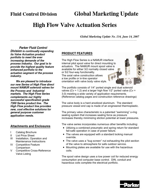
Fluid Control Division Global Marketing Update High Flow Valve Actuation SeriesGlobal Marketing Update No. 134, June 14, 2007 __________________________________________________________________________________________________________________________________ Parker Fluid ControlDivision is continually expanding its Valve Actuation product portfolio to meet the ever increasing demands of the process industry. Our goal is to provide the highest quality feature enhanced portfolio to the actuation segment of the process industry.We are pleased to introduce our new Series of High Flow direct mount NAMUR solenoid valves for the Process and Industrial markets. The High Flow Series complements our highly successful specification grade 7300 Series product line. The High Flow product line provides new, cost effective solutions for general purpose customer application needs.Attachments and EnclosuresI Catalog BrochureII List Price SheetIII Installation, Operation andMaintenanceInstructionsIV Competitive FeatureComparisonV CompetitiveCross-Reference ValveListing PRODUCT FEATURESThe High Flow Series is a NAMUR interfaceinternal pilot spool valve for direct mounting toactuators. The NAMUR mount spool valve isavailable for either 3/2 normally closed valveor 5/2 four-way functionality.The axial valve construction allowsa low profile or in-line operatororientation with valve body valve style.The portfolio consists of 1/4” ported single and dual solenoid valves (Cv = 1.2) and a larger high flow 1/2” ported valve (Cv = 3.0) meeting a wide variety of application requirements. (Reference catalog pages and construction reference drawings)The valve body is a hard anodized aluminum. The standard pressure vessel end cap is made of an engineered thermoplastic.The primary valve characteristic is a patented “swimming” o-ring sealing system that increases sealing force as pressure increases thereby minimizing stiction potential at lower pressures. The valve series incorporates numerous other benefits including: •Utilizing a combined pneumatic and spring return for standard fail-safe operation in case of power failure.•The valves are equipped with a standard locking manual override.•The valve uses a “bug screen” nut exhausting the pilot section of the valve to atmosphere for safe outdoor service.•Mounting plates are available for use with the hazardous coils.The spool valve design uses a low power coil for reduced energy consumption and computer base control. DIN, conduit and hazardous coils complete the electrical portfolio.Global Marketing Update No. 134, June 14, 2007 __________________________________________________________________________________________________________________________________ OPERATION FUNCTIONALITY3/2 Single Solenoid (4 ported, 2 position)NAMUR valve, solenoid operated, for 3-way normally closed operation. In case of an electrical or air failure, valve returns to a fail-safe position through pneumatic and assisted spring return.5/2 Single Solenoid (5 ported, 2 position)NAMUR valve solenoid operated, for 4-way, 2 position operation. In case of an electrical or air failure, valve returns to a fail-safe position through pneumatic and assisted spring return.5/2 Dual Solenoid (5 ported, 2 position)NAMUR valve used for 4-way, 2-position operation. In case of an electrical or air failure, valve “fails as is”. Therefore, valve remains in last position upon failure and will not return to a predetermined position.5/3 Dual Solenoid, Center Position Closed (5 ported, 2 position)NAMUR valve used for 4-way, 2-position operation. In case of an electrical or air failure, the spool returns to the center position thereby removing pressure to the cylinder ports.TECHNICAL PRODUCT CHARACTERISTICSThe new line of valve actuation products offer many features and benefits as follows:Modular construction – Facilitates use of various body configurations and coil options.Mounting Configurations - Direct mount NAMUR pattern with axial operator orientation for single and dual solenoid models for low profile mounting requirements.Manual Override – Standard on all models for manual valve operation during start-up and diagnostic procedures.7mm (1.2Cv ) and 12mm (3.0 Cv) orifice sizes – Multiple sizes to meet various application demands to ensure the solenoid valve is properly sized.Body Materials - Lightweight anodized aluminum.Spool Design – Stainless steel with NBR sealing materials.Exhaust Pilot Cap– Protected pilot sleeve exhaust using “Bug Screen” nut. Helps protect against plugging, dirt, and insects, etc.Ratings – Meets pressures up to 150 psi.Ambient Temperatures – From 14°F (-10°C) to 122°F (50°C), serving most temperature environments. Fluid Temperatures – From 32°F (0°C) to 104°F (40°C).COIL PRODUCT CHARACTERISTICSA selection of low power encapsulated coils as follows:•DIN coil - with 3-pin DIN 43650 type B plug.•Conduit - 3-wire coil.•Hazardous – 3-wire coil with FM and CSA agency approvals meeting Class 1, Groups A,B,C,D and Class II, Groups E,F,G. Meets EEx m II T4 Division 1 requirements.NAMUR INTERFACEMany actuator manufacturers utilize a common mounting pattern referred to as a NAMUR interface for mounting configurations of solenoid valves.The actuator interface dimensions for NAMUR mounting of the pilot valve to the actuator is shown below (dimensions in millimeters).MATERIALS OF CONSTRUCTIONBody: Anodized AluminumEnd Covers: Thermoplastic – Glass-Filled Polyamid 6/6Plunger: 430 Stainless SteelCore Tube: 304 Stainless SteelSteelSprings: StainlessSeals: NBRCages: Polyamide Filled ThermoplasticSteelSpool: StainlessShading Rings: CopperMOUNTING BOLTSThe standard NAMUR interface includes (2) mounting bolts to mount the valve on to the actuator, a positioning stud and two O-rings seals.MOUNTING PLATESDue to the increased width of the hazardous coil to comply with FM and CSA certifications, a mounting plate must be installed as shown in the photograph.The mounting plate kit contains the plate, 2 o-rings, and 2 longer mounting screws.For the ¼” port valve, order kit N60001. For the ½ “ port valve, order kit N60002.ElectricalStandard voltages and voltage code:VOLTAGE CODE 12VDC A 24VDC B 120/60 C 240/60 D 24/60 E 120/50-60 F 240/50-60 GSolenoid Coil SpecificationsThe electrical portfolio is comprised of general purpose class F DIN coil per 43650B and conduit class H coils rated for NEMA classification Types, 1, 2, 3, 3S, 4, 4X. In addition, the hazardous location class H coil is rated for NEMA classification Types 7 and 9; Class I, Divisions 1 and 2, Groups A,B,C,D and Class II, Division 1, Groups E,F,G. The coils are rated for continuous duty application demands.The electrical selector table summarizes each coil specification:Coil Type Coil Part Number Class Protection Construction Agency22mm DINND1x F DIN connector needed for IP65 protection Per DIN 43650B epoxy moldedUL,CSA Conduit –Ordinary locationNC1x H Type 1,2,3,3S,4,4X Epoxy molded, ½ inch NPT conduit None Conduit –Hazardous locationNH1xHType 4X,7,9½ inch NPT conduitCSA,FMCOMPETITIVE FEATURES AND BENEFITSThe primary valve characteristic is a patented “swimming” o-ring sealing system that increases sealing force as pressure increases thereby minimizing stiction potential at lower pressures.The diagram shows a typical cross section view of the valve.valve-head to keep moisture out in brass or in stainless steel available on request, only in combination with alu-head Spool in stainless steel, other inner-parts made from brass, NBR, POM stainless steel Fiber-enforced PA-head, aluminium-version on request 360° turnable,Date CodePRODUCT LABELINGValves are sold in either:• A modular format ordering pressure vessel and coil separately. • Fully assembled with coil assembled to pressure vessel.In either case, the pressure vessel valve body provides the valve identification information defining the valve part number, performance rating and date code. Sample pressure vessel markingCoils will be marked with the appropriate part number, voltage and wattage, and agency information.Sample coil markingAll valves will be packaged with an installation, operation and maintenance instruction sheet indicating conformity with the CE Mark.ORDERING INFORMATIONPRODUCT OFFERINGReference the enclosed catalog brochure (Attachment I) describing the High Flow Series product offering. The catalog pages describe the valve features, general specifications, valve and electrical selection guide, dimensional drawings, and ordering information.PRICINGPressure Vessel list prices for the High Flow NAMUR Series valves are shown in Attachment II. ORDERING INFORMATIONThe Series uses a simple valve number to identify each model. The valves are available fully assembled or in modular form allowing application flexibility in electrical selection. The electrical parts can also be purchased in modular form.Reference the enclosed catalog pages.•When purchasing individual pressure vessels, select the pressure vessel shown on the catalog page and associated list price.•When ordering electrical parts, select the electrical part and associated list price for standard voltages.•When ordering complete valves, add the list price of each component to determine the complete list price for the fully assemble valve selected.The voltage code is the last character of the fully assembled valve or electrical part selected. For example, selecting a single solenoid, 5/2 configuration, 120/60 DIN coil, the complete valve number is:U341N03 + ND1FAVAILABILITY AND DELIVERYParker Fluid Control Division plans to maintain an appropriate service level of finished goods stock to meet business demand of the following NAMUR mount valves. If finished goods stock is available, units will be shipped within 5 business days from receipt of order for order quantities of 25 units or fewer:Product Class 1 Items:U331N03U341N03ND1B, ND1F, ND1G - 24vdc, 120vac, 240vacNC1B, NC1F, NC1G - 24vdc, 120vac, 240vacNH1B, NH1F, NH1G - 24vdc, 120vac, 240vacProduct Class 4 Items - the estimated lead-time (subject to change) is 4 weeks from receipt of order.U347N03U342N03U331N04U341N04ND1A - 12vdcNC1A - 12vdcNH1A - 12vdcAs always, for larger customer orders requiring shorter lead-times, Parker Fluid Control Division will work jointly with each customer by establishing finished goods items to meet customer provided forecasts.DISCOUNTSParker Fluid Control Division’s standard published discounts apply. Current terms and conditions apply for the product.SERVICERETURNSParker Fluid Control Division’s standard return policy applies.REPAIR PARTSParker Fluid Control Division is NOT offering component repair kits for field service at this time. Since the valve is a small, cost effective product, industry experience shows the process markets will replace the complete valve rather than rebuild the valve in the field.INSTALLATION OPERATION AND MAINTENANCE (IOM)An IOM has been created describing valve operation, installation and mounting instructions, maintenance, and troubleshooting procedures for the high flow Series NAMUR valves. Reference Attachment III, IOM HN01.WARRANTYParker Skinner’s standard 2 year warranty policy applies to the pressure vessel, coil and enclosures.PROMOTIONPromotional materials have been prepared to expedite introduction into the market place.CATALOG / LITERATURE• A new catalog has been created containing the features, specifications and outline drawings of the high flow Series valves.• A product launch announcement containing product introduction materials and detailed competitor information will be distributed to each Territory Sales Manager.TRAINING•Each Territory Sales Manager should contact their respective Fluid Control Division Authorized Distributor and Valve Actuation Accounts to arrange training.•The new high flow Series valves will be included in Fluid Control Division’s Valve Actuation Training Program.•Samples of the new high flow Series actuation valves will be provided upon receipt with a complete sample request form following standard Skinner Valve ™ sample procedures.PHASE-OUT OF 2340, 3300 and 7341 Series Product LinesThe introduction of the new product line has resulted in significant product overlap with the 2340, 3300 and 7341 series valves. Therefore, we are taking the following actions to phase out these product lines. Due to the low volume of many of the products, the old families will be replaced by the new High Flow NAMUR valve as follows:The Phase In – Phase Out schedule will begin upon introduction of the new High Flow NAMUR valve. It may be possible to order a specific older model until current inventory is fully depleted at which time the old product will no longer be available. Parker reserves the right to discontinue the old products sooner if conditions warrant.COMPETITIVE REVIEWReference Competitive Feature Comparison of select valves in Attachment IV. The attachment contains a broad selection of valves representative of the competitive offering.Attachment V provides a competitive cross-reference part number listing based on available information for the individual competitors.ASCO is considered the market leader for actuation valves. Other primary competitors include Versa, Automatic, and Herion.Below is a general description of the competitive product offerings.ASCOThe ASCO 8551 Series offers a product line of NAMUR and pipe mount versions. The portfolio consists of pad mount valves with various operator configurations with single and dual solenoids.In general, the ASCO 8551 Series consists of:•Anodized aluminum and stainless steel body using resilient spool construction. •Convertible 3-way and 4-way models based on the newer version. The older version consists of non-convertible 3-way and 4-way models that are similar to the 7300 Series. •20/35 to 150 psi operating pressure differential.•Single and dual solenoid, vertical and axial operator models available.•Cv 0.50 to 0.86.•AC versions from 2.5 watts to 10.1 watts.DC versions from 3.0 watts to 11.6 watts.•DIN, watertight and explosion solenoids available based on model.The Parker High Flow Series NAMUR mount valves are specified to meet the application requirement. A conversion or mounting plate is not required when using a DIN coil. The valve mounts directly to the actuator in a very cost-effective and efficient manner.VersaVersa offers a series of valves for process control markets including applications for pneumatic actuators and 316 stainless valves for corrosive requirements. The valve offering consists of NAMUR, body ported, lockout valves, latching and manual reset valves and redundant solenoid valves.Specific to the actuation area, Versa offers a convertible 3-way / 4-way version and direct acting 3-way pad mount valve. Available options include Intrinsically Safe, Low power and CENELEC flameproof enclosures.•3/2, 5/2 port plug versions. Valves field convertible by relocating a port plug converting from 3-way to 4-way or 4-way to 3-way.•Anodized aluminum, stainless steel and brass body using resilient spool construction. •Single and dual solenoid models (5/2) and dual solenoid centered position (5/3) with standard manual override.•15 to 115 psi operating pressure, Cv 0.75.•DIN, conduit and explosion solenoids available based on model.•8.5 watt AC, 10.5 watt DC.•Class A or F insulation.Automatic Valve Co. (AVC)They are considered the low price player in the market. They offer a NAMUR mount COMPACT Series. The series has limited options, but offers the ability to order valves with the solenoid on the left or right side.•3/2, 5/2 port plug versions, 1/4” npt porting only.•Anodized aluminum body using resilient spool construction.•40 to 150 psi operating pressure differential, Cv 1.0.•NEMA 4 and 7 solenoids, remote air and manual operators.•DIN, conduit and explosion solenoids available based on model, coil ratings to Class H. Herion•3/2, 5/2 port plug versions, NAMUR mount, 1/8” NPT, ¼” NPT, ½” NPT.•Anodized aluminum body using resilient spool construction.•25 to 150 psi operating pressure differential, Cv 1.1 to 1.4.•NEMA 4 and 7 solenoids, manual operators.•Low power coils available at reduced ratings.•DIN, conduit and explosion solenoids available based on models.•Locking and momentary manual override available.•Requires spacer plate for hazardous coil.Max-Air TechnologyU.S. division of M Technology Srl located in Italy. Also offer rack & pinion actuators and position indicators and mechanical switches that can be assembled as a complete unit.•3/2, 5/2 port plug versions, 1/4” npt porting only.•Epoxy coated aluminum body with plated spool. And standard manual override.•DIN and explosion solenoids available based on model, Class F standard, Class H optional. •Uses a pop-up air indicator located in pilot section to indicate if the solenoid valve is pressurized.•Optional IS and ATEX DIN coil construction.Q&A SESSIONQ? Why did we introduce the High Flow NAMUR Series valve product line?The principle reason for introducing the valve line is to meet increasing market demands for smaller, cost effective valve models for the process valve actuation markets. The Parker 7300 Series valve line offers a high-end specification grade product in multiple bodymaterials to meet general purpose ordinary requirements to the most stringent application requirements. Also, the 2340 series of aluminum body valves lacked a suitable hazardous coil limiting application potentials.The new product line overcomes the 2340 series deficiencies at a most competitive price for general purpose application requirements. The portfolio includes expanded models with higher flow factors for larger actuator designs. The new line includes a 1/2” namur valve to accommodate the trend toward larger actuators and higher flows.Finally, we’re continuing our strategic thrust in the process markets with a new product offering and responding to competitive product positions.Q? Will the High Flow Series product line replace the 2340 Series and 3300 Series valves?In a word, yes. First, since the introduction of the 2340 series and 3300 series valves(dating back to the late ‘90’s), many changes have taken place in the market. The general purpose ordinary location market generally does not require the high technical or safety standards found in these product lines. Due to deficiencies in the former product lines, specifically the lack of a hazardous coil, we were not able to meet the availability and price competitiveness. The current product lines are focused toward higher technicalrequirements resulting in low-volume market segments and overlap price-wise with the 7300 Series valve lines. To reduce complexity and offer a simplified, cost-effective processactuation valve line, the 2340 catalog portfolio will (eventually) be phased-out.Q? Describe the comparison to the 7300 product line.The High Flow Series offers similar product features and benefits compared to the 7300 Series, in particular:• Total modularity.•Interchangeable electrical parts.•Unique spool designs to eliminate risk of sticking.•High quality in proven valve designs.•Standard manual override.The distinctive features of the High Flow Series compared to the 7300 Series include:• Smaller physical size.•More cost effective compared to 7300 with manual override (for certain type application needs).Q? Where must the 7300 series valves be used versus the new line?The 7300 series contains features, multiple operator configurations and electrical coilsappropriate for more demanding critical applications including:•Higher flows appropriate for higher actuator torque specifications.•Intrinsically Safe (IS) and ultra low power environmental conditions.•Manual reset options used as a safety device on solenoid valves to prevent process resumption without manually resetting each valve.•Low temperatures application demands of –40°F/C.•Field convertible manual overrides including locking and momentary requirements. Q? Will a conversion plate eventually become available?The product line contains individual 3-way and 4-way valve configuration. When utilizing a DIN coil, this method provides the most cost-effective, competitive solution. Granted, whilea conversion plate offers the benefit of using one style valve, it also adds significant andunnecessary costs. Since the valve is focused and priced to pursue higher volumerequirements, the valve functionality will be known.。
TLV SDS M0000-70 自动压力减小阀门说明说明书

Cv Values
Cv (US) Cv (UK) Kvs (DIN)
Nominal Valve Size (mm)Βιβλιοθήκη 152025
32
40
50
65
80
100
3.8
6.9
11.1
15.5
24.0
37.2
59.3
85.0
128
3.2
5.7
9.2
12.9
20.0
31.0
49.4
70.8
107
3.3
5.9
9.5
Union
Valve
For details see COSR instruction manual
Steam-using Equipment
For primary pressure of 1.4 MPaG, set pressure 0.6 MPaG, and saturated steam flow rate 750 kg/h, select an appropriate size.
2.1
Maximum Operating Temperature (°C) TMO
220
Primary Pressure Range (MPaG)
1.35 – 2.1
Adjustable Pressure Range (all conditions must be met)
Within 10 – 84% of primary pressure but with a minimum pressure of 0.55 MPaG
2. Since point D is located between 15 mm and 20 mm, the larger size, 20 mm, should be chosen.
Ruelco MP-4 手动启动的三位一体式手动阀门操作指南说明书

“MP-4”MANUAL RELAYMODEL 1901OPERATION MANUAL OMP # 1901 08/02 Revision 0I. PRINCIPLE OF OPERATIONThe Ruelco “MP-4” relay is a pilot operated manual relay. It is a three (3) way, normally closed valve with a palm knob for relay position indication and manual operation. In the closed position, pneumatic or hydraulic pressure coming into the “Inlet” port is locked from the “Outlet” port by the upper shaft o-ring. The spring keeps the spool in the down or closed position. The valve is opened by manually pulling the palm knob outward, thus moving the shaft assembly upward. The detent pin is then pushed “In” to lock the relay open until a pneumatic signal is applied to the pilot cap of the relay. This pneumatic pressure acting on the piston causes the detent pin to drop “Out” of the locked position. When the relay is in the open position, it causes the middle o-ring to engage the body seal bore and the upper o-ring to disengage from the body seal bore respectively. Supply pressure at the “Inlet” port may then flow through the body to the “Outlet” port.When the pneumatic signal is removed from the pilot supply “PS”, the spring moves the shaft assembly downward. This causes the upper O-ring to disengage the body seal bore. This also allows the middle O-ring to engage the body seal bore and prevent flow into the “IN” port. With the supply pressure blocked, pressure will flow from the “OUT” port and exit through the “VENT” port. The relay may also be closed manually by pushing the palm knob inward.II. INSTALLATIONThe “MP-4” can be mounted either vertically, horizontally, panel mounted (with optional panel mount nut), or supported by piping from any of its ports. If it is supported by piping, care should be taken that the strength of the pipe fittings used is adequate to prevent the fitting from breaking off in the relay body should the relay be inadvertently struck.Proper pipe thread sealant should be used on any pipe fittings threaded into the relay ports. If stainless steel fittings are used, a sealant that will prevent galling is required. Supply gas or hydraulic fluid flowing through the relay should be free of large dirt particles. If compressed air is used, it does not have to be lubricated. If natural gas is used, it should contain as little condensate as possible. This will extend the life of the seals.If the relay is going to be installed in a location where the stem will be exposed to excessive paint, sand, drilling fluids, etc., the use of the optional stem protector is recommended. The stem protector does not affect the operation of the relay and will prevent the relay from jamming should the exposed portion of the shaft accumulate excessive trash or debris.III. DISASSEMBLY (REFER TO SPEC.SHEET 1901)Tools required are as follows:• 7/16” open end wrench or suitable adjustable wrench•1” open end wrench or suitable adjustable wrench•7/8” open end wrench or suitableadjustable wrench and flat bladescrew driver (for removal ofoptional stem protector)A. PARTIALDISASSEMBLY1. To replace the three (3) shafto-rings (Item7) and the pistonseal (Item 11), the relay doesnot have to be completelydisassembled.2. Place the 7/16” wrench onthe lock nut and rotate itclockwise while holding theknob (Item 1) until the knobis loose. Rotate the knobcounterclockwise andremove it from the shaft sub-assembly . If the optionalstem protector is installed,pull the relay knob outwarduntil the flat on the sealwasher (Item 16) is visible.Use the 7/8” wrench to rotatethe seal washer clockwiseuntil the knob is loose.Remove the knob and sealwasher simultaneously(rotate counterclockwise).3. Remove the retaining ring(Item 13) from body (Item 8)in order to remove base(Item 14).4. Push the shaft subassemblythrough the valve body andslide the spring (Item 9) offthe relay shaft.5. The seals on the shaft maynow be replaced as perinstructions given in therepair section of this manual(IV.). B. FULLDISASSEMBLY1. Follow the procedures statedunder partial disassembly. Ifthe relay is panel mounted, itis not necessary to removethe relay from the panel, butit is recommended so thatadequate inspection andcleaning of all parts may beperformed.2. Using a flat blade screwdriver, remove the RetainingRing (Item 13) from the body(Item 8)3. Remove the base (Item 14),followed by the shaftsub-assembly.4. To remove the stemprotector housing (Item 16),use the flat blade screwdriver and rotate the screws(Item 4) counterclockwise.5. The relay is now ready to becleaned and repaired.IV. REPAIR AND ASSEMBLY1. Remove the piston and shaft sealsfrom the shaft assembly.2. Using an appropriate safety solvent,clean all parts.3. Inspect the shaft assembly for anymajor damage such as burrs andnicks. Also inspect it forstraightness. Replace the shaftassembly is damaged.4. Examine the relay body and head forany damage such as burrs, nicks,etc. Replace any damaged pieces.5. Replacement seals from a Ruelcoproduct repair kit are required forproper relay performance. It isrecommended that all seals belubricated before and afterinstallation with a high qualitysilicone base grease.6. Install the piston seal onto the shaftsubassembly. NOTE: This is a cuptype seal. The inside of the cupshould be facing toward the bottomof the shaft subassembly as shown.Be sure that the inside lip of the sealis completely pushed into the pistongroove.7. Lubricate the shaft o-rings and installon the shaft subassembly.8. Lightly lubricate the large bore in therelay body.9. Slide the spring over the shaftsubassembly and slide the shaft intothe relay body.10. Lubricate the base o-ring (Item 12)and install into the valve body.11. Insert the base in the body andsecure using the retaining ring.12. If a stem protector is to be used,locate the holes in the protectorbody over the threaded holes in thehead. Insert the two (2) screws androtate them clockwise to tighten.13. Thread the lock nut over the shaftsubassembly until it reaches the lastthread. Do not tighten. Rotate theknob over the shaft thread until ittouches the lock nut. Hold the knoband turn the lock nutcounterclockwise with the 7/16”wrench until firmly tightened.14. To install the stem protector washerand the knob, thread the washer asfar down onto the shaft as possible.Screw the knob onto the exposedthreads above the washer, but donot tighten. Pull the relay shaft fullyoutward and thread the protectorwasher until it stops. NOTE: Theprotector seal should now becompletely inside the protectorhousing. Release the relay knob andallow the shaft subassembly toretract. Rotate the knob clockwiseuntil it stops. Pull the knob outwardagain and use the 7/8” wrench toturn the protector washercounterclockwise until tight.V. RECOMMENDEDMAINTENANCE Procedure and IntervalOperate Manually – Every thirty (30) days.Disassemble, inspect and lubricate – Yearlyor as required.Replace all seals – Every two (2) years oras required.。
Watts BF-03-M2 BF-04-M2型号双腿铜阀门商品说明说明书

Series BF-04-M2 Wafer Series BF-03-M2Full LugSeries BF-04-M2Waferbody design features lifting lugs while lug body design features dead-end service. Incorporating a 200psi (13.8 bar) pressure rating for 2" – 12" (50 – 300mm) and a 150psi (10.3 bar) pres-sure rating 14" – 24" (350 – 600mm), the BF series butterfly is standardly constructed of a ductile iron body with a choice of either ductile iron, aluminum bronze, or 316 stainless steel discs and 416 stainless steel or 316 stainless steel shaft. A phenolic-backed seat (2"-12", 50-300mm) or aluminum-backed seat (14" – 24", 350-600mm) prevents the seat from collapsing or dislodging. Standard seat materials available include EPDM, Buna-N and Viton. The BF Series mounting pad is designed to ISO 5211 standard to accommodate lever handles, gear opera-tors, or actuation.The Watts Series BF butterfly valves are designed and manufac-tured for use with ANSI 125 or 150 Class flanges and comply with API 609 and MSS-SP 67 standards to meet the stringent requirements of HVAC, Irrigation, OEM, Commercial, Institution-al, and Industrial applications.Features• B ody – Available in Full Lug (BF-03-M2) and Wafer (BF-04-M2) styles designed for use between ANSI 125 and 150 flanges. Face-to-face dimensions comply with API 609 and MSS-SP-67. All valves are designed to accommodate 2" of insula-tion. The mounting pad is designed to ISO 5211 standard. The body material is ASTM A-536 ductile iron.• D isc – Disc edge is machined and polished 360 degrees to assure leak-tight shutoff while minimizing operating torque. Positive, disc-to-shaft connection is provided by stainless steel precision taper pins. Discs are available in ductile iron, alumi-num bronze, or 316 stainless steel.• S eat – Phenolic or aluminum backed, non-collapsible, resilientseat is mechanically secured to provide dead-end service to the full pressure rating in lug style valves. Full 360 degrees seal-ing isolates the body components from the media and provides the primary shaft seal. Seats are available in EPDM, Buna-N, and Viton.• S haft – One-piece shaft delivers positive disc-to-seat location with maximum strength. 416SS is standard shaft with ductile iron and aluminum bronze disc. 316SS shaft is standard with 316SS disc models.Three shaft bushings provide shaft support for proper align-ment and minimal shaft deflection. Bi-directional shaft seals prevent external contamination of the stem area and provide backup for the primary shaft seal formed by the disc/seat interface.• H andle – ISO 5211 top work design allows for standard 10 position handle 2" – 6" (50 – 150mm) and manual, worm gear operators for 8" – 24" (200 – 600mm) sizes. An infinite positioning locking handle is an available option on 2" – 12" (50 – 300mm) valves. The posi-lok handle provides an infinite position stop, a memory stop, and a pad-locking device in the fully closed position.Job Name ––––––––––––––––––––––––––––––––––––––––––– Contractor ––––––––––––––––––––––––––––––––––––––––––––Job Location ––––––––––––––––––––––––––––––––––––––––– Approval –––––––––––––––––––––––––––––––––––––––––––––Engineer ––––––––––––––––––––––––––––––––––––––––––––– Contractor’s P.O. No. ––––––––––––––––––––––––––––––––––Approval –––––––––––––––––––––––––––––––––––––––––––––Representative ––––––––––––––––––––––––––––––––––––––––Watts product specifications in U.S. customary units and metric are approximate and are provided for reference only. For precise measurements, please contact Watts Technical Service. Watts reserves the right to change or modify product design, construction, specifications, or materials with-out prior notice and without incurring any obligation to make such changes and modifications on Watts products previously or subsequently sold.* T he wetted surface of this product contacted by consumable water contains less than one quarter of one percent (0.25%) of lead by weight.How to Order Watts Series BF-M2MaterialsSize:2" thru 24"Series: 03: Full Lug, 04; Wafer Body: 1: Ductile Iron Disc: 1: Ductile Iron 2: Aluminum Bronze 3: 316 Stainless Steel*Shaft:1: 416 Stainless Steel316SS on stainless steel disc models*Seat:1: EPDM 3: Viton 2: Buna-N Operator: 0: No handle - 2" thru 24" G: Gear Operator - 2" thru 24" 5: Standard handle (10-position only) - 2" thru 12" P: Positioning / Locking Kit with handle - 2" thru 12"14BF 03121 1G M2Body: ASTM A-536 Ductile Iron.Bushing: Duralon(3): Teflon ® - Dacron inner liner bonded to fiberglass - epoxy resin outer shell 2"-12" (50-300mm), Bronze 14"-24" (350-600mm) Stem O-rings: Buna-NDisc: ASTM A-395 Ductile Iron / Electroless Nickel PlatedASTM A-148 Aluminum Bronze ASTM A-351 316 Stainless SteelShaft: 416 Stainless Steel316 Stainless Steel on 316SS Disc Models Seat: EPDM: +5°F to 248°F (-15°C to +120°C) Buna-N: +14°F to 176°F (-10°C to +80°C)Viton: -4°F to 302°F (-20°C to +150°C)Note:Do not use EPDM when hydrocarbons are present.C V RATING (Full Open)Size C V Rating in.C v 213521⁄22203302460051,02261,57983,136105,340128,2501411,9171616,3881821,7052027,9082443,116DimensionsBC DAButterfly ValveB C D E F H I Jmm in.mm in.mm in.mm in.mm in.mm in.mm in.mm in.mm 27363⁄816115⁄84211⁄85431⁄16771011333⁄4953⁄8929567⁄817513⁄44511⁄26431⁄16771011341⁄41083⁄8930871⁄818113⁄44511⁄87931⁄16771011343⁄41203⁄8934677⁄820025211⁄810535⁄8921011661⁄161547⁄161137283⁄821323⁄165617⁄812435⁄8921011971⁄81811⁄21339787⁄822623⁄165611⁄815635⁄8921011983⁄162081⁄213479101⁄426023⁄8601820251251422101⁄42605⁄816540111⁄229223⁄86617⁄825151251429125⁄832013⁄1621626131⁄43373761117⁄830161501432143⁄4375––679141⁄23683761131⁄83336150–321515⁄16405––762153⁄440033⁄887153⁄839167⁄8175–33181⁄2470––800165⁄842241⁄8105173⁄844267⁄8175–382011⁄16525––897187⁄848051⁄81302193⁄849381⁄4210–41221⁄4565––1088221⁄856261522233⁄859481⁄4210–50275⁄16693––†Weights are for valves with ductile iron or aluminum bronze discs. 2" – 12" have levers; 14" – 24" have bare shafts. Refer to Watts F-CDBF for gear operator weights.TOP PlATE DRIllING TAPPED lUGDATA KEY WAY WEIGhT †OBOLTCIRCLE NO.BOLT Q in.mm in.mm Holes P in.mm 871⁄4741⁄41214"-11UNC x 15⁄8"–61⁄4751⁄21404"-11UNC x 13⁄4"–71⁄4761504"-11UNC x 13⁄4"–73⁄81071⁄21918"-11UNC x 2"–123⁄81081⁄22168"-10UNC x 23⁄16"–163⁄81091⁄22418"-10UNC x 23⁄16"–201⁄213113⁄42988"-10UNC x 23⁄8"–291⁄213141⁄436212"-9UNC x 25⁄8"–481⁄2131743212"-9UNC x 3"1⁄4 x 11⁄4 6 x 32781⁄213183⁄4476121"-8UNC x 3"1⁄4 x 11⁄4 6 x 329911⁄1618211⁄4540161"-8UNC x 33⁄8"5⁄16 x 113⁄168x4614011⁄1618223⁄457816"-7UNC x 41⁄8"3⁄8 x 19⁄1610x401887⁄8222563520"-7UNC x 51⁄8"3⁄8 x 19⁄1610x402487⁄822291⁄275020"-7UNC x 6"1⁄2 x 23⁄813x60450M2 = SeriesQ(4) "O" Diameter of holes on the "N" bolt AF▼h Dia.J Across flats45°EGICES-BF-03-M2/BF-04-M2 0935 © 2009 WattsUSA: 815 Chestnut St., No. Andover, MA 01845-6098; Canada: 5435 North Service Rd., Burlington, ONT. L7L 5H7; www.wattscanada.caA Watts Water Technologies Company。
Eaton M-Force三相断路开关说明书

DescriptionEaton's Cooper Power™ series M-Force™ switch is a distribution-class, gang-operated, factory unitized three-phase overhead loadbreak switch. The M-Force switch is offered in distribution voltage classifications of 15.5 kV , 27 kV , and 38 kV . The M-Force switch may be used for linesectionalizing, paralleling, by-passing, or isolating.M-Force stands for “Magnetic Force”. Eaton has the only reverse loop contacts found on distribution-class sidebreak switches; a contact usually reserved for higher priced transmission switches. The reverse loop contacts utilize high current magnetic forces for added reliability. The reverse loop design allows for high contact pressure to be maintained during fault conditions. This feature prevents pitting and distorting of the switch blade and contacts even under severe momentary overload.M-Force ™three-phase switchCatalog Data CA008004ENM-Force three-phase switch Effective March 2020Figure 3. Illustration of M-Force switch.3Catalog Data CA008004ENEffective March 2020M-Force three-phase switch /cooperpowerseriesFigure 4. Horizontal switch configuration.“B”“C”“D”“A ”“B”“B”“B”“B”“A ”“E”“D”“A ”“E”“D”“C”“B”“F”“A ”4Catalog Data CA008004ENEffective March 2020M-Force three-phase switch/cooperpowerseries5Catalog Data CA008004ENEffective March 2020M-Force three-phase switch /cooperpowerseries6Catalog Data CA008004ENEffective March 2020M-Force three-phase switch/cooperpowerseries7Catalog Data CA008004ENEffective March 2020M-Force three-phase switch /cooperpowerseries8Catalog Data CA008004ENEffective March 2020M-Force three-phase switch/cooperpowerseriesCoastal M-Force SwitchesCoastal M-Force switches utilize a corrosion- resistant fiberglass crossarm as a sturdy base for three robust phase units. Stainless steel components and bell crank assembly allow the switch to maintain reliable operation after exposure to salt, moisture and other environmental contaminants.Coastal M-Force Three-Phase Switch Catalog Number Configuration9Catalog Data CA008004ENEffective March 2020M-Force three-phase switch /cooperpowerseriesDefinition of optionsB–Provisions for crossarm support bracketsThe "B" option supplies two adjustment mounting brackets oncrossarm. This allows the customer to install support brackets/alley arms to the crossarm. The support brackets are not included.C–Captive hardware on terminal padsThis option provides two 1-3/4" captive stainless steel studs on each NEMA ® two-hole pad. These are usually used in conjunction with compression terminals. This option is incompatible with Option U.E–Extension linksThis option provides two 14" extension links on each conductor dead-end bracket, six per switch.F–Bonded control handleThis option provides a grounding strap and connector that is attached to the manual operating handle. This is a standard feature on torsional control designs.G–Reciprocating handles with interlocksThis option provides manual interlocks on switches and is available on switches sold in pairs only. When ordered with this option, end user information such as; utility name, contact person, address, and phone number will have to be provided prior to order input as required by the manufacturer of the interlocks.H–Lightning arrester bracketsThis option provides provisions for the mounting of six lightning arresters per switch.I–Steel interphase rodThis provides a 1" O.D. steel interphase rod. The standard rod is UV inhibited fiberglass.J–Provisions for neutral wireThis option provides a hole and spacing for a pin type insulator to be located on the crossarm to accommodate the neutral wire.K–Provisions for sensorsThis option provides longer phase unit bases that will accept sensors to be easily mounted if the manual switches are to be retrofitted for SCADA with a motor operator at a later date.R–Additional nameplate on handleThis option provides a nameplate fixed to the manual control handle in addition to the nameplate mounted on the switch crossarm.S–Ice shieldsThis option provides ice shields on each switch clip contact. This allows the switch to be opened or closed under a 3/4" ice build up.T–Grounding connectorThis option provides a grounding lug on the crossarm mounting bracket. This allows for the utility to ground the switch base to the pole ground.U–T erminalsThis option provides connectors on each two-hole NEMA ® pad with a conductor range of #2-500 MCM. This option is incompatible with Option C.V–Pole mounting bandThis option provides the additional support of adjusting pole bands that are attached to the pole mounting bracket.1–One additional control rod 2–T wo additional control rods10Catalog Data CA008004ENEffective March 2020M-Force three-phase switch/cooperpowerseriesWhen one section of fiberglass is ordered for reciprocating control, the top section will be designated as that segment.11Catalog Data CA008004ENEffective March 2020M-Force three-phase switch /cooperpowerseriesM-Force three-phase switch Eaton 1000 Eaton Boulevard Cleveland, OH 44122United States Eaton’s Power Systems Division 2300 Badger Drive Waukesha, WI 53188United States /cooperpowerseries© 2020 Eaton All Rights Reserved Printed in USA Publication No. CA008004EN/MCG Catalog Data CA008004EN Effective March 2020For Eaton’s Cooper Power series product information call 1-877-277-4636 or visit: /cooperpowerseries.Eaton is a registered trademark.All other trademarks are property of their respective owners.。
Eaton GEB4040FFM 系列固定电流断路器说明书

Eaton GEB4040FFMEaton Series G molded case circuit breaker, EG-frame, GE, Complete breaker, Fixed thermal, fixed magnetic trip, Four-pole, 40A, 480 Vac, 25 kAIC at 240 Vac, 18 kAIC at 415/480 Vac, Line and load end caps, Metric, 0% protected neutral poleGeneral specificationsEaton Series G complete molded case circuit breakerGEB4040FFM 7821169843812.99 in 5.5 in4 in 4 lb Eaton Selling Policy 25-000, one (1) year from the date of installation of the Product or eighteen (18) months from the date of shipment of the Product, whichever occurs first.IEC Rated Product NameCatalog Number UPCProduct Length/Depth Product Height Product Width Product Weight WarrantyCertificationsMetric25 kAIC at 240 Vac18 kAIC at 415/480 VacEGGEComplete breakerLine and load end caps480 Vac40 A0% protected neutral pole Fixed thermal, fixed magnetic Four-pole Application of Multi-Wire Terminals for Molded Case Circuit Breakers Application of Tap Rules to Molded Case Breaker TerminalsCircuit breaker motor operators product aidStrandAble terminals product aidCurrent limiting molded case circuit breaker module for series G, JG and CLMulti-wire lugs product aidHigh performance operating handles for Series G circuit breakers product aidPower metering and monitoring with Modbus RTU product aidMotor protection circuit breakers product aidComprehensive circuit protection for control panel applicationsCurrent limiting molded case circuit breaker module product aidPlug-in adapters for molded case circuit breakers product aidSeries G MCCB quick selectorMolded case circuit breakers providing higher levels of selective coordination product aidBreaker service centersMolded case circuit breakers catalogEaton's Volume 4—Circuit ProtectionFixed and Adjustable Thermal Trip GE Moulded Case Circuit BreakerMOEM MCCB product selection guideEaton Specification Sheet - GEB4040FFMNG and ND-Frame molded case circuit breakersMounting hardware Interrupt ratingFrameCircuit breaker type Circuit breaker frame type TerminalsVoltage rating Amperage Rating ProtectionTrip TypeNumber of poles Application notesBrochuresCatalogsInstallation instructions Specifications and datasheetsEaton Corporation plc Eaton House30 Pembroke Road Dublin 4, Ireland © 2023 Eaton. All Rights Reserved. Eaton is a registered trademark.All other trademarks areproperty of their respectiveowners./socialmedia。
- 1、下载文档前请自行甄别文档内容的完整性,平台不提供额外的编辑、内容补充、找答案等附加服务。
- 2、"仅部分预览"的文档,不可在线预览部分如存在完整性等问题,可反馈申请退款(可完整预览的文档不适用该条件!)。
- 3、如文档侵犯您的权益,请联系客服反馈,我们会尽快为您处理(人工客服工作时间:9:00-18:30)。
阀组系列产品
1.VX-32型三阀组
2.M364W-420P-35/54型三阀组
3.M564W-320P-54五阀组
4.EFZ-320C(P)型二阀组
5.引压接头
VX-32型三阀组
使用说明书
北京远东仪表有限公司
1 用途
VX-32型三阀组可与本公司与美国EMERSON TM公司合资生产的1151、3051系列等差压变送器配合使用,其作用是从引压点将信号引入差压变送器正负测量室使引压点与测量室接通或断开。
2 基本参数
a. 公称压力:32MPa
b. 环境温度:-30℃~+93℃
c. 介质温度:≤150℃
d. 重量:约2.5kg
e. 外形尺寸:230×120×180mm
f. 材质:1C r18 Ni 9Ti
3. 基本结构与工作原理
3.1 基本结构(如图1)
图 1
3.2 工作原理
M364W型三阀组由两端的引压阀和中间的平衡阀组成,三个阀结构相同,均采用聚四氟乙烯填料和9Cr18阀瓣,通过手柄旋转阀杆可实现阀门的开启与关闭。
关闭二引压阀、打开平衡阀时,正负测量室相通。
打开二引压阀、关闭平衡阀时,两引压管分别与正负测量室相通、两输出端压力不同。
引压阀一开一闭、打开平衡阀时,两输出端压力相同。
4 安装方法
将三阀组装有聚四氟乙烯密封圈的二出压孔对准差压变送器法兰侧面1/4ANPT引压孔,均匀旋紧四条
螺栓,以保证密封。
5 注意事项
本产品出厂前已经打压试验合格,请不要任意松动零件,调整、维护请在专业人员指导下进行。
6 成套性
使用说明书 1份
检验合格证 1份
密封垫圈外径24.5mm内径19mm厚2mm 2件
螺栓 7/16-20UNF-2A 1″ 4件
焊接管接头 2件
7. 订货须知
根据选用的压力变送器量程代号。
选择三阀组型号(见表)
8. 售后服务
本产品自发售之日起18个月内,在用户完全按使用说明书规定使用的情况下,如出现不符合技术要求的质量问题,我公司负责修理或更换。
M364W-420P-35/54型三阀组
使用说明书
北京远东仪表有限公司
1 用途
M364W三阀组可与本公司与美国ROSEMOUNT公司合资生产的1151、3051系列等差压变送器配合使用,其作用是从引压点将信号引入差压变送器正负测量室使引压点与测量室接通或断开。
2 基本参数
a. 公称压力:42MPa
b. 环境温度:-30℃~+93℃
c. 介质温度:≤150℃
d. 材质
密封副:9Cr18
结构件:1C r18 Ni 9Ti
填料:聚四氟乙烯
e. 外形尺寸:220mm ×120 mm×36 mm
f. 重量:约2kg
g. 连接型式及尺寸
输入端:NPT1/2 中心距:35mm
输出端:法兰中心距:54 mm
3 基本结构与工作原理
3.1基本结构如图1
3.2 工作原理
M364W型三阀组由两端的引压阀和中间的平衡阀组成,三个阀结构相同,均采用聚四氟乙烯填料和硬质合金锥形阀瓣,通过手柄旋转阀杆可实现阀门的开启与关闭。
关闭二引压阀、打开平衡阀时,正负测量室相通。
打开二、关闭平衡阀时,两引压管分别与正负测量室相通、两输出端压力不同。
引压阀一开一闭、打开平衡阀时,两输出端压力相同。
4 安装方法
将三阀组装有聚四氟乙烯密封圈的二出压孔对准差压变送器二方法兰侧面1/4ANPT引压孔,均匀旋紧四条螺栓,以保证密封。
5 注意事项
本产品出厂前已经打压试验合格,请不要任意松动零件,调整、维护请在专业人员指导下进行。
6 成套性
a. 标准附件
使用说明书1份
检验合格证1份
密封垫圈∅23.8mm×∅18mm×3mm 2件
螺栓7/16-20UNF-2A 3″4件
b. 选配附件
焊接管接头2件
7. 售后服务
本产品及附件,自发售之日起18个月内,在用户完全按使用说明书规定使用的情况下,如出现不符合技术要求的质量问题,我公司负责修理或更换。
M564W-320P-54五阀组
使用说明书
北京远东仪表有限公司
1 用途
M564W型五阀组可与我公司与美国ROSEMOUNT公司合资生产的1151、3051系列等差压变送器配合使用,其作用是从引压点将信号引入差压变送器正负测量室,使引压点与测量室接通或断开,还有气液排放及调表接口。
2 基本参数
a)公称压力 32MPa;
b)环境温度 -30℃~+93℃;
c)介质温度≤150℃;
d)材质
密封副9Cr18
结构件 0Cr18Ni9Ti
填料聚四氟乙烯;
e)外形尺寸 270mm×120mm×36mm;
f)重量约2.5kg;
g)连接型式及尺寸
输入端 NPT1/2 中心距 54mm;
输出端法兰中心距 54mm。
3 基本结构与工作原理
3.1基本结构如图1
3.2 工作原理
M564W型五阀组由两端的引压阀和中间的平衡阀以及两个排气排液阀组成,五个阀结构相同,均采用聚四氟乙烯填料和硬质合金锥形阀瓣,通过手柄旋转阀杆可实现阀门的开启与关闭。
关闭二引压阀、打开平衡阀时,正负测量室相通;
打开二引压阀、关闭平衡阀时,两引压管分别与正负测量室相通、两输出端压力不同;
引压阀一开一闭、打开平衡阀时,两输出端压力相同。
4 安装方法
将五阀组装有聚四氟乙烯密封圈的二出压孔对准差压变送器二方法兰侧面1/4ANPT引压孔,均匀旋紧四条螺栓,以保证密封。
5 注意事项
1)本产品出厂前已经打压试验合格,请不要任意松动零件;
2)调试前请仔细阅读使用说明书,检查管道压力,确定无误,方可进行调试,以免压力
过高损坏阀组。
6 成套性
a)标准附件
使用说明书一份;
检验合格证一份;
密封垫圈∅23.8mm×∅18mm×3mm 2件;
螺栓 7/16-20UNF-2A 3″ 4件;
b)选配附件
焊接管接头 2件。
7. 售后服务
本产品及附件,自发售之日起18个月内,在用户完全按使用说明书规定使用的情况下,如出现不符合技术要求的质量问题,本公司负责修理或更换。
EFZ-320C(P)型二阀组
使用说明书
北京远东仪表有限公司
一.用途
EFZ-320C、P型二阀组适用于智能压力变送器产
品配套,其作用是从引压点将信号引入压力变送器测量室,使引压点与测量室接通或断开,为压力变送器不可缺少的配件。
二.技术性能及特点
1.工作压力:≤32MPa
2.工作环境:环境温度:-30℃~90℃
介质温度:≤150℃
3.重量:1.4kg
4.外形尺寸:121×160×50mm
5.材质:不锈钢1Cr18Ni9Ti
6. 特点:结构简单、体积小、重量轻。
三.基本结构与工作原理
EFZ-320C、P型二阀组由一个引压阀和一个取样阀组成,二个阀的组件结构相同。
阀的通或断是由阀杆组件导致阀球的移动而定,当用手旋动阀柄(1)时阀杆(3)在阀芯内作往复移动,通过阀杆手动阀球(5)离开或靠近阀座。
实现阀门的开启或关闭。
阀座与阀杆组件的密封采取阀球密封,阀杆用不锈钢材料,阀杆与阀芯之间采用填料密封套不致渗漏。
1
2
3
4
5
6
1 阀柄
2 密封套
3 阀杆
4 填料
5 阀球
6 螺塞
四. 安装使用及注意事项
1. 安装使用
先将二阀组的外螺纹NPT1/2″-14与压力变送器连接,然后将引压点外螺纹NPT1/2″-14与二阀组连接并旋紧。
2. 注意事项
(1)切勿松动阀杆组件;
(2)正确组装阀组引压及输压的方向。
五.故障排除
1. 阀球关闭不严。
主要原因是阀芯组部位有损伤或阀芯组部位不清洁,应对阀芯组部位研磨和去除脏物。
2. 填料处有渗漏现象。
(1)预压环未压紧,应旋紧螺母;
(2)阀杆表面有划伤,应根据情况更换阀杆;
(3)阀杆旋转有卡阻现象,是阀杆扭曲变形,应调直或更换阀杆。
六.订货须知
1. 配用的压力变送器型号及连接尺寸;
2. 工作压力;
3. 介质温度;
4. 材质:一般型或防腐型。
焊接管接头
焊接接头是阀组的配件,1/2NPT螺纹端拧入阀体的输入端,另一端与管路焊接,六角螺母与接头连接的密封材料为聚四氟乙烯。
焊接管接头分为1/2NPT和1/4NPT两种规格。
1/2焊接管接头示意图。