DYT BZ 磁力耦合器安装维护手册(DYT-BZ30)
10-磁力搅拌器使用与维护标准操作规程

.
1. 目的:保证磁力搅拌器使用的准确性。
2.范围:本公司磁力搅拌。
3. 责任部门:生技部或质保部
4. 内容
操作步骤和要求:
4.1初始试机:
4.1.1将电源开关(机器左侧面下方)置于OFF档
4.1.2电源插头插入机身
4.1.3接通电源后,机器处于待机模式,数显屏右侧小数点点亮。
4.2搅拌:
4.2.1将电源开关打开置于ON档。
4.2.2使用右侧的圆形操作旋纽设定机器的速度。
4.3加热:
4.3.1使用左侧的圆形操作旋纽为加热盘设置目标温度
4.3.2设定值显示于数显屏上,如果加热盘开始加热,红色LED指示灯亮
4.4结束关机,搅拌完成后,关闭两侧加热及调速旋纽,关闭电源开关;
4.5同时清理机器平台,及时填写使用记录;
4.6维护与保养
4.6.1使用时,调节转速和温度的按钮,小心旋转;
4.6.2使用结束后擦拭台面;
4.6.3如使用加热功能后,操作人员不得接触台面,待冷却后再擦拭;
4.6.4使用过程中如有异常,需及时向设备管理人员汇报;
4.7 支持性文件:相应型号磁力搅拌器使用说明书。
.;。
ERITZ MAGNETICS 2400 型号悬挂式电磁铁安装、操作与维护说明书

Installation, Operation a nd Maintenance InstructionsERIEZ MAGNETICSH EADQUARTERS: 2200 ASBURY ROAD, ERIE, PA 16506–1440 U.S.A.W ORLD AUTHORITY IN ADVANCED TECHNOLOGY FOR MAGNETIC, VIBRATORY and INSPECTION APPLICATIONSSM-321DIntroductionThis manual applies to the two basic types of Eriez Magnetics SE-2400 electromagnets: chute style and suspended type. The slight differences in installation and maintenance procedures for these magnets are detailedin the text.A careful reading of these Installation, Operation and Maintenance Instructions will assure your magnet’s most efficient and dependable performance.If there are any questions or comments about the manual, please call Eriez Manufacturing at 814/835-6000 for assistanceCAUTION ‑ STRONG MAGNETThis equipment includes one or more extremely powerful magnetic circuits. The magnetic field may be much stronger than the Earth’s background field at a distance several times the largest dimension of the equipment.• If you use a heart pacemaker of similar device you must neverapproach the equipment because your device may malfunction in the magnetic field, with consequences up to and including death.• To avoid serious pinch‑type injuries caused by objects attracted to the magnet, keep all steel and iron objects well away from the equipment. Do not allow hands, fingers, and other body parts to be caught between the equipment and “workpiece” being lifted.• Keep credit cards, computer disks, and other magnetic storage devices away from the equipment because magnetically stored information may be corrupted by the magnetic field.• Keep electronic devices, such as computers or monitors, away from the equipment because exposure to the magnetic field may result in malfunction or permanent damage to such devices. Contact Eriez if you have a question regarding these precautions.CAUTIONSafety labels must be affixed to this product. Should the safety label(s) be damaged, dislodged or removed, contact Eriez for replacement.Suspended Electromagnets3Table of ContentsSUSpENDED ElECTROMAGNETSDESCRIPTION ......................................................................................................4INSTALLATIONGeneral ............................................................................................................5 Magnet Positions .............................................................................................5 Suspension Height (6)Burden Depth (6)Wiring ..............................................................................................................6OPERATION ..........................................................................................................7MAINTENANCE For Chute Type & Manual Cleaning Models . (7)For Self-Cleaning Models (7)WARNING .............................................................................................................8TROuBLESHOOTINGRectifier Troubleshooting Data Sheet (9)General ..........................................................................................................10 Adjustment Guide for Chute Magnets ...........................................................10 Adjustment Guide for Manual Cleaning units (11)Adjustment Guide for Self-Cleaning units (11)4Suspended electromagnets are heavy duty DCpowered separators designed for removing iron from material that is being moved on wide, non-troughed belts or other wide flat conveyors. The speciallydesigned box-shaped structure houses oil-cooled coils that generate a powerful magnetic field.These units are furnished in two styles: chute style and suspended, with the later being available in either a manual cleaning type or self-cleaning type.Suspended units can be installed in either Position 1 (over the conveyor head pulley) or Position 2 (across the width of the conveyor). Sizes are readily available to accommodate most any conveyor width.DescriptionManual cleaning magnets are intended for use where the amount of iron to be retrieved is not abnormally high. An adjustable means of suspension is achieved through use of four turn-buckles supplied with the unit. T o clean accumulated tramp iron from the magnet it is necessary to shut off the power.Self-cleaning units are basically manual cleaning magnets with short belt conveyors built around them to provide automatic discharge of tramp iron. They are suspended in the same manner as manual cleaners.FIGURE 1Typical SE-2400 suspended electromagnetFIGURE 2Typical SE-2400 chute electromagnetSuspended Electromagnets5InstallationGENERAluse care in uncrating to avoid damage to the equipment.Check the area where the magnet is to be installed for magnetic material. All magnetic material within the field of the magnet (up to 4' (122 cm) may become induced and tend to attract iron. This can interfere with the magnet’s performance. Change to non-magnetic material.For Chute Style: These are shipped with mounting pads suitably positioned for installation at the angle specified on the order (usually 45-60°). When positioned at the specified angle, the integral oil expansion chamber will be properly oriented. For Suspended Models: Be sure the magnet is oriented properly. In all installations, the external oil expansion chamber must be at right angles to the direction of material flow and on the high side if installed at an angle.Check the pressure relief valve located on the high end of the oil expansion chamber to make sure it is free to operate. This is done by pulling the stem and releasing it. It is spring loaded and will re-seat itself when released.MAGNET POSITIONS Chute StylePlace the magnet on a foundation with the face on the same plane as the working face of the chute. Holes are provided for foundation bolts to secure the unit in place once it has been positioned. Joints between the magnet and chute work should be as smooth as possible to assure an uninterrupted material flow and provision should be made for gaining access to the magnet face for removing accumulated iron (See Figure 3).Suspended Style position 1 (in‑line)The installation of a suspended magnet over thetrajectory of material discharged from the belt conveyor is referred to as POSITION 1 (See Figure 4 & 5).For optimum separation in Position 1 installations, provisions must be made to adjust the location of the magnet to suit the trajectory of the material.For Position 1 installations with conveyor belt speeds of less than 350 fpm (107 m/min), greater separation will be achieved by using a non-magnetic head pulley.If a Self-Cleaning unit is being installed, examine the area to make sure that the self-cleaning belt around the separator has adequate room to run properly and that provisions have been made to collect thedischarged tramp iron. A hinged non-magnetic splitter, adjustable in length, will be required to preventextracted tramp iron from re-entering the product.FIGURE 4Manual cleaning position 1FIGURE 5Self-cleaning position 1FIGURE 36FIGURE 6Manual cleaning position 2FIGURE 7Self-cleaning position 2Position the magnet so that the face of the belt is approximately 2" (50 mm) from the trajectory of the material being discharged. The centerline of the magnet should be approximately perpendicular to the material at that point.position 2 (Cross‑belt)Installation of the separator over the moving bed of material at right angles to the conveyor is referred to as POSITION 2 (See Figures 6 and 7). This location sometimes presents a more difficult separation problem than Position 1 and may require a lower suspension. Position 2 mounting is generally not recommended where belt speed is in excess of 350 fpm (107 m/min.).For Position 2 installations, steel conveyor idlers cannot be used in the length of the conveyor beneath the separator. Any conveyor idlers beneath the separator must be made of rubber, wood, or some other non-magnetic material.Both the Manual Cleaning and the Self-Cleaning units should be installed on the centerline of the material conveyor.SUSpENSION HEIGHTThese magnets are designed for 20" (51 cm)suspension height. This height should be considered a maximum and the magnet should be lowered as close to the actual burden as possible. When lowering the magnet to the burden, be sure that plowing does not occur. If the unit is a self -cleaning magnet, make sure that the separator belt has room to operate and discharge tramp iron properly. A clearance of 3" (75 mm) between the magnet or belt and the top of the burden should be maintained for self-cleaning units. This clearance can be reduced to 2" (50 mm) for manual cleaning units.BURDEN DEpTHThe best separator performance is achieved by controlling the burden depth. A plow or levelerpositioned above the conveyor and before the magnet will help level high spots or surges in Position 2 installations. For Position 1 installations, therecommended installation location is calculated on expected tonnage. Any variation from this rate changes the trajectory of the burden with respect to the workingsurface of the magnet and may result in poor separation.WIrINGWiring for Eriez electromagnets is very simple (See Figure 8). Connect the two DC leads from the DC power source to the two terminal posts in the magnet outlet box and tighten the terminal nuts.CAUTIONAfter installation and prior to start‑up, check the oil level at the Oil level plug located on the side corner of the magnet near the expansion tank. If the level is low, add oil of the type specified on the plate attached to the top of the magnet beside the Oil Fill plug.Installation (cont.)Suspended Electromagnets7CAUTIONDo not attempt to turn the terminal poststhemselves. This may result in internal damage.FIGURE 8Power from existing DC sourceLeads from DC Power SourceDC Kick- Absorbing SwitchOperationSTArT -UP OF SELF-CLEANING UNITS1. Be sure the frame is visibly square and has notbeen damaged or twisted.2.After installation, momentarily close the AC switch to the belt drive to determine if the belt tends to wander and, if so, in which direction.3.Belt Adjustmenta. The SE-2400 magnets have a four-pulley design and two tracking adjustments. The bottom tail pulley is initially used to take up the slack and track the belt. If tracking cannot be achieved by this adjustment, the small pulley located on the same end has a horizontal adjustment available to aid in tracking the belt.b. To track the belt, the pulley should be moved in a direction to tighten the belt on the side to which the belt wanders.NOTE: Never start the belt drive and allow it to run continuously until the belt is properly tracked.MaintenanceFOr CHUTE TYPE &MANUAL CLEANING MODELS:1. The oil level should be checked periodically. Thelevel must be maintained. Replace the oil as required with the same brand and type as noted on the plate beside the Oil Fill Plug. Do not attempt to mix brands or types since many substitutes for the original are not compatible. Check the oil level only when the magnet is cold.2. Be sure the expansion tank pressure relief valve is free. This should be checked frequently.NOTE: Normal external operating temperature of Eriez oil-cooled electromagnets is approximately 160°F (70°C) for air-cooled magnets,approximately 150°F (65°C). These temperatures are extremely hot to the touch. Skin burns at 130°F .FOr SELF-CLEANING MODELS:1. Lubricate bearings on a schedule consistent withother equipment in use with your product and environment. An NGL1 No. 2 lithium-base grease is recommended.2.Check V-belt tension frequently. Adjust by tightening the reducer torque arm as required.3.For motor and reducer maintenance, refer to the manufacturer’s instruction sheets packed with the shipment.4.If the separator is to be installed inside afabricated enclosure, provisions must be made to maintain and adjust moving parts as required.5. After 250 hours of running check pulley hubs and tighten set screws to 17 lb. ft. torque.6.Belt tracking should be checked frequently and adjusted as necessary. Tighten the belt on the side to which the belt wanders.7.Once the belt has been tracked, furtheradjustment may be required to achieve proper tension. Excess tension applied in an effort to keep the belt flat against the face of the magnet can lead to pulley, shaft or bearing failure.It is normal for the belt to sag due to its own weight and this becomes more prevalent on thelarger units. Efficient operation can be achieved without applying excess tension so the belt should be tightened only enough to prevent slipping on the pulleys when it is conveying iron off the face of the magnet. usually a sag of up to 2" (50 mm) is not detrimental unless it interferes with material flow. See Figure 9.About every two years, have the oil tested for the dielectric rating. Minimum should be 20 kv. If lower than 20 kv, oil can be filter pressed to bring back a higher dielectric rating or replace with new oil using the same brand.Belt is too tightBelt is too looseFIGURE 9 Suspended electromagnets with self-cleaning belts are normally suspended above conveyor belts away from personnel working areas. Eriez has no control over this location or adjacent areas.under certain conditions it may be necessary for the user to install additional safety devices to protect operating personnel.Suspended electromagnets with self-cleaning belts have pinch points where the belt goes over the pulleys. When the belt is running, this is a hazardous area. Workers should be instructed not to perform duties on this equipment unless it is shut down and the electric supply source is locked out.Warning and caution plates and decals on the magnet must not be removed or painted over. It is important that these warnings and cautions be legible and that they be followed.WarningBelt must just touch the magnet corners8TroubleshootingSuspended Electromagnets9Troubleshooting (cont.)pROBlEM pROBABlE CAUSE SOlUTIONMagnet will not attract iron a. Magnet is not turned on or the magnetvoltage is lowb. Parts not being attracted are non-magneticc. Induced iron in the area of the magnetprohibits the extraction of tramp irond. Magnet is overheatede. Magnet coils are groundedf. Magnet coil is shorted or opena. Check power switch and check DC voltage at magnetterminals. Adjust as required.b. Check missed tramp iron with small permanent magnetto confirm that it is magnetic.c. Check area around the separator with a small steelprobe to see if the structure or conveyor componentsare themselves acting as a magnet and attracting iron.R eplace with a non-magnetic material as required.d. Check for proper DC voltage at the magnet terminalsand check for proper current. Current should not beless than approximately 30% lower than nameplatecurrent. Correct voltage. Allow magnet to cool.e. Take megohm reading between each magnet terminaland ground. 50 megohms should be minimum reading.f. Check for rated current at rated voltage at magnet ormeasure DC resistance of cold magnet. The resistanceshould equal the nameplate voltage divided bynameplate amperes.Oil Leak a. Damaged unitb. Excessive internal pressurea. Check and repair as required. Magnet may be weldedor patched as required BuT EXTREME CAuTIONMuST BE TAKEN TO PREVENT FIRE DuRING ANYWELDING.b. Check freedom of pressure relief valve and replaceif required.TABlE 1General troubleshooting chartpROBlEM pROBABlE CAUSE SOlUTIONMagnet will not attract iron a. Magnet face is overloaded withalready-extracted irona. Examine face of the magnet for build-up of excessiveq uantities of extracted tramp iron. Discharge morefrequently as required.TABlE 2Adjustment guide for chute magnets.(All general items also apply)10Suspended Electromagnets 11pROBlEM pROBABlE CAUSE SOlUTIONMagnet will not attract iron a. Magnet face is overloaded with already-extracted iron b. Magnet set too far from burden c . Magnet set too close to burden d. Magnet is not installed at the proper suspension heighta. Examine face of the magnet for build-up of excessive q uantities of extracted tramp iron. Discharge more frequently as required.b. Check for proper clearance between the magnet and burden. Adjust for proper gap.c. Check for proper clearance between the magnet and the burden. If too close, material surges can occur and the surge may act as a wiper.d. Check location of magnet with respect to burden and confirm that it is within the recommended suspension height at the centerline of the magnet.TABlE 3Adjustment guide for manual cleaning units .(All general items also apply)pROBlEM pROBABlE CAUSE SOlUTIONTramp iron re-entering the product a. Not enough clearance for the iron to be discharged from the product magnet b. Splitter improperly positioned c . Magnet is not installed at the proper suspension heighta. For self-cleaning units in position 2, check to see that enough clearance has been allowed between bottom of magnet and edge of conveyor belt for maximum sizes to be discharged. Adjust as necessaryb. For self-cleaning units in position 1, check splitter for proper location and clearance with respect to the magnet. A djust splitter angle and length as requiredc . Check location of magnet with respect to burden and confirm that it is within the recommended suspension height at the centerline of the magnet.TABlE 4Adjustment guide for self-cleaning units .。
接触网地磁感应器、断合标安装维修
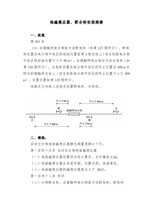
地磁感应器、断合标安装维修一、技规第491条(4)在接触网电分相前方设断电标(如第127图所示),断电标设置在电分相中性区段起始位置前第2根支柱上(该支柱距电分相中性区段起始位置不小于80 m);在接触网电分相后方设合电标(如第128图所示),合电标设置在电分相中性区段终止位置后400 m处附近的接触网支柱上(该支柱距电分相中性区段终止位置不小于400 m)。
设置位置如第129图所示。
线路反方向按上述规定设置断电标、合电标。
二、维规:自动过分相地面磁感应器静态测量周期6个月;第一百四十五条自动过分相地面磁感应器(一)地面磁感应器设置符合设计要求,允许偏差±2m。
(二)地面磁感应器应安装牢固,完整无损,表面清洁。
(三)地面磁感应器的磁感应强度应大于 36GS。
第一百四十二条标识(三)分相断合标。
在接触网电分相前方设断电标,断电标设置在电分相中性区段起始位置前第 2 根支柱上(该支柱距电分相中性区段起始位置不小于 80m);在接触网电分相后方设合电标,合电标设置在电分相中性区段终止位置后 400m 处附近的接触网支柱上(该支柱距电分相中性区段终止位置不小于 400m)。
线路反方向按上述规定设置断电标、合电标。
有电力机车上线的线路,还应在“断”标背面加装“机车合”标。
三、高速铁路地磁感应器、断合标的安装相对位置(汉十东线)四、检修内容。
(高铁作业指导书)(一)地磁感应器1. 磁感应装置防护罩表面清洁,无碰伤。
2. 磁感应装置防护罩表面清洁,无太多铁屑、铁粉等吸附物。
3. 螺栓开口销掰开角度大于 120 度。
4. 化学锚栓无脱落、拔起等异常现象。
(二)断合标1. 检查标志的状态,安装位置是否符合规定,字迹是否清晰,安装是否牢固,各零部件螺栓是否紧固,是否采取防腐,安装标准统一,有无严重锈蚀和脏污,设置位置是否符合设计要求,埋设是否牢固可靠,在任何情况下便于了望,不得侵入限界。
2. 用皮尺测量标志牌的实际装设位置是否符合规定。
液力偶合器安装,操作和维护说明书

(第 4 页,共 6 页) G、将液力偶合器和或接合器上的孔与 G 型偶合器套管和垫圈上的孔对正,然后 首先在输出边插上紧固件。拧紧所有的紧固件到表 2 中指定的拧紧力矩。
表 2---G 型法兰紧固件拧紧力矩
H、重新安装起吊时用的两个周向螺栓和垫片,紧固到表 3 中指定的力矩。
表 3—HF 型周向紧固件大小和拧紧力矩及丝杆直径
起吊
大约相隔 90 度卸掉周向的两个螺栓。插上带有垫圈和螺母的丝杆(第 4 页,表 3),像图 2 所示吊起偶合器。
关键安装提示
---填充和排泄孔处的易熔塞拧紧时不要超过指定的力矩。过大的拧紧力矩会引起 划坏铝丝。
---如图 3 和 5 所示安装液力偶合器。偶合器的输出接合边应连接到被驱动设备。 把偶合器的输出边连接到驱动装置(通常是电动机)将导致性能降低。
制造商
液体
年检
检查轴偶合和正式基准的对准程度。较大的不对齐会给连接设备传递有害的载 荷,引起故障。
推荐对偶合器和液体进行年检。在极端的或非常的环境下使用,或偶合器易于过 热时,要提高检查偶合器和液体的频率。过热变黑和散发燃烧气味的液体一定要 更换。定期的检测偶合器液体样品,给出基于液体降级率的经济的更换周期。连 续运转温度不能超过 100 度。检查螺栓紧固到合适的力矩。
2、安装 HF 型液力偶合器
A、液力偶合器装运的时候带有输入和输出接合器,装配的形式如第 1 页图 1 所 示。注:大小为 185 的不需要输入接合器,因为齿轮偶合器套管是直接紧固到 液力偶合器。 B、检查 G 型偶合器垫圈,如果需要,修剪垫圈超出直径的部分。 C、将 G 型偶合器垫圈放在套管法兰面上。 D、根据手册 458-110 中的指导,润滑每一个 G 型偶合器。 E、如图 5,尽可能接近中心线,在 G 型毂之间放置液力偶合器装配体。 F、在输入和输出接口器的相对孔间插入弹性间隙盘(大小 1010G 不需要)。
磁力驱动泵应用流程中关注事项及日常维护说明

文档归纳不易,仅供学习参考磁力驱动泵应用流程中关注事项及一般维护说明磁力驱动泵应用流程中关注事项及一般维护说明关注事项:一、泵在应用中环境温度应小于40℃,电动机温升不宜超出75℃。
二、磁力驱动泵正确运作1000H后,应拆检轴承与端面动环的磨坏状况,并调换不可以再用的易损件。
三、因磁力驱动泵轴承的冷却与润滑是靠被传输的液体,所以绝对禁止空运作,同时减少在运转中途停电后再启用时所导致时空载运作。
四、较之传输液为易沉淀结晶的液体,应用后应及时清洗,排净泵内积液。
五、被传输液体中,假设含有固体颗粒,泵入口要加过滤网:如含有铁磁质微粒,需加磁性过滤器。
六、被传输的液体及其温度应在泵材可以范畴内。
工程塑料泵的应用温度60℃,金属泵的应用温度100℃,传输吸入压头不超过0.2MPa,极限运转压头一、6MPa,比重不超过1600Kg/m3,粘度不超过30X10-6m2/S的不含硬颗粒与纤维的介质。
一般维护:一、轴承损坏:磁力驱动泵的轴承使用的材质是高比重碳,如遇泵断水或泵内有杂质,就会导致轴承的损坏。
圆筒形连轴器内外磁转子间的同轴度需求假设得不到确保,也会直接影响轴承的寿命。
二、泵流量缺少:导致泵流量缺少的首要因素有:叶轮损坏,转速不够,泵扬程太高,管内有杂物堵塞等三、泵扬程缺少:导致这种障碍的因素有:传输液体内有气体,叶轮损坏,转速不够,传输介质的密度过大,泵流量过大。
四、轴断裂:磁力驱动泵的泵轴使用的材质是99%的氧化铝瓷,泵轴断裂的首要因素是,因为泵空运作,轴承干磨而将轴扭断。
拆开泵检查时可看到轴承已磨坏严峻预防泵断裂的首要方法是减少泵的空运作。
五、磁力驱动泵打不出介质:磁力驱动泵打不出介质是泵最易出现的障碍,其因素也较多。
首先应检查泵的吸入管线是不是有漏汽的地方,检查吸入管内气体是不是排出,磁力驱动泵内灌注的介质量是不是满足,吸人管内是不是有杂物堵塞,还应查一查泵是不是反转(尤其是在换过电动机后或供电线路维修过后),还要注意泵的吸上高度是不是太高。
磁力仪安全操作及保养规程
磁力仪安全操作及保养规程前言磁力仪是一种应用广泛的精密仪器,通常用于磁学、物理、地质、化学等领域的实验和研究。
磁力仪的安全操作和保养规程对于确保磁力仪的正常运行和实验数据的准确性至关重要。
本文旨在向使用磁力仪的使用者介绍磁力仪的安全操作和保养规程,以保证实验的安全性和可靠性。
安全操作规程1. 装置和连接磁力仪的安装和连接必须符合厂家的规定,所配备的电源必须符合安全标准并正确接地。
在安装和连接磁力仪时,必须确保周围环境干燥、清洁,并保持良好的通风条件,防止积尘和湿度影响磁力仪的性能。
2. 采集样品在进行实验之前,必须事先准备好所需的材料和设备,并确保在进行采样时所用的仪器(比如,取样瓶和移液器)是干净和合适的。
3. 开机操作步骤打开电源开关前,请仔细阅读磁力仪使用手册,并按照以下步骤开机: 1. 将电源线插头插入电源插座 2. 打开电源开关 3. 等待一段时间,当磁力仪稳定后,进行实验数据的采集和处理4. 操作细节在实验过程中,必须遵循以下基本原则: - 严格按照实验的操作流程进行 - 防止样品与设备接触 - 防止磁力仪受到震动 - 防止其他电子设备或引起电磁干扰的设备污染磁力仪5. 关机操作实验结束后,按照以下步骤关闭磁力仪: 1. 关闭电源开关 2. 按照磁力仪使用手册的要求进行后续操作6. 安全事项在使用磁力仪时,必须注意以下安全事项: - 不要使用明火或其他易燃物质靠近磁力仪 - 不要将电线裸露或与其他设备和箱子混放 - 不要长时间使用磁力仪,以防过度耗损或性能下降 - 磁力仪故障时,必须按要求进行维修,不要私自拆卸保养规程1. 清洁和维护在每次实验之后,必须对磁力仪进行清洁和维护,包括: - 清洁磁力仪的外部表面,并保持储存区域干燥 - 在使用前检查磁力仪的柜体和电线,确保无损坏或漏电现象 - 定期进行磁力仪的校准,验证精度2. 维护记录保养记录是至关重要的,它可以帮助对磁力仪进行有效的维护管理。
电磁防护固态去耦合器安装步骤

固态去耦合器安装步骤固态去耦合器采用固态技术非金属壳体,能控制管道上交流杂散电流或雷电流对埋地管道的影响,延长管道的使用寿命。
同时,又能防止杂散电流在管道上汇集后对人体的危害以及对通信线路的干扰。
作为直流隔离和交流耦合装置,BX-SSD/EX-100用于防止阴极保护电流达到预定的阈值电压,同时还能传导感应的交流电。
当电压力图超过阈值电压时,SSD立即切换到短路模式,以提供过压保护.当过电压过去之后,又自动切换回到直流隔离模式。
这样的运行方式可以进行无数次,这通常是由于交流故障电流或雷电电流引起。
SSD的标准阂值电压为-2V/+2V。
阈值电压可以是absolute value电压,或峰值电压,在此电压处切换发生,此电压为跨于隔离器两端的市流和交流峰值电压之和。
这使跨于SSD端子上的箝位电压很低。
一、安装前的准备工作1. 确定安装位置:固态去耦合器要安装在信号源和负载之间,离信号源和负载的距离应适中。
2. 确认工作电压:购买固态去耦合器时要确认其工作电压是否与待安装系统相符,以免损坏设备。
3. 检查接口类型:固态去耦合器的接口类型应与信号源和负载的接口类型一致,以确保信号传输的稳定可靠。
4. 准备必要工具:安装固态去耦合器需要使用螺丝刀、扳手等工具,需要提前准备好。
二、安装步骤1. 关闭待安装系统电源:在进行固态去耦合器安装前,必须先关闭待安装系统的电源,断开信号源和负载的连接线。
2. 固态去耦合器安装:将固态去耦合器通过螺丝或夹子固定在预定位置上,并连接信号源和负载的连接线。
3. 安装电源线:将固态去耦合器的电源线接入电源插座处。
4. 启动待安装系统:在安装完成后,启动待安装系统,检查信号是否传输正常。
三、注意事项和常见问题解决方法1. 注意安装位置:固态去耦合器的位置要尽可能靠近信号源和负载,避免过长的信号传输线路。
2. 注意接口类型:选择固态去耦合器时要注意接口类型的匹配,以免影响信号传输质量。
DYT BZ 磁力耦合器安装维护手册(DYT-BZ75)

DYT-BZ75磁力耦合器安装维护手册目录1. 安全注意事项 (1)2. DYT BZ型磁力耦合器介绍 (1)2.1. 什么是DYT BZ型磁力耦合器 (1)2.2. DYT BZ型磁力耦合器保护措施 (1)2.3. DYT BZ型磁力耦合器特点 (2)2.4. DYT BZ型磁力耦合器结构示意图 (2)2.5. DYT BZ型磁力耦合器匹配负载功率范围 (3)3. 检查包装箱及注意事项 (3)3.1. 检查包装箱 (3)3.2. 注意事项 (3)4. 安装 (4)4.1. 准备工作 (4)4.2. 安装轮毂 (4)4.2.1. 径向跳动公差要求 (4)4.2.2. 轴向端面跳动公差要求 (4)4.2.3. 电机轴和负载轴的安装要求 (4)4.3. 安装胀紧套 (5)4.4. 安装DYT BZ型磁力耦合器方法 (6)4.4.1. 整体安装法 (6)4.4.2. 拆分安装法 (7)5. 调试运行 (7)5.1. 注意事项 (7)5.2. 安装防护罩 (7)5.3. 调试运行 (7)5.4. 安装调整和维护 (8)5.5. 系统调试 (8)6. 保修 (8)6.1. 保质期 (8)6.2. 更换零配件 (8)7. 附录A 工具和安装人员要求 (9)8. 附录B 锁紧螺栓规格和规定的紧固件扭矩 (10)9. 附录C 磁力耦合器安装检查表 (10)10. 附录D 磁力耦合器系统调试数据表 (1)1.安全注意事项●在安装时,导体盘、工具和紧固件与磁体盘保持一定安全距离,磁体盘具有非常大的吸引力,被吸附上很难分开。
注意导体盘与磁体盘的安装,防止身体压伤;●在调试、运行时,工作人员需要戴护目镜,避免穿戴宽松的服饰,戴手套等物品,可能会发生意外事故;●在调试时,检查周围是否有零散的具有导磁性物品,可能会被吸附到磁体盘上,使磁力耦合器发生故障;●在正式运行前,DYT BZ型磁力耦合器必须安装防护罩。
2.DYT BZ型磁力耦合器介绍2.1.什么是DYT BZ型磁力耦合器DYT BZ型磁力耦合器是利用磁感应原理进行传递扭矩的装置。
- 1、下载文档前请自行甄别文档内容的完整性,平台不提供额外的编辑、内容补充、找答案等附加服务。
- 2、"仅部分预览"的文档,不可在线预览部分如存在完整性等问题,可反馈申请退款(可完整预览的文档不适用该条件!)。
- 3、如文档侵犯您的权益,请联系客服反馈,我们会尽快为您处理(人工客服工作时间:9:00-18:30)。
DYT-BZ30磁力耦合器安装维护手册目录1. 安全注意事项 (1)2. DYT BZ型磁力耦合器介绍 (1)2.1. 什么是DYT BZ型磁力耦合器 (1)2.2. DYT BZ型磁力耦合器保护措施 (1)2.3. DYT BZ型磁力耦合器特点 (2)2.4. DYT BZ型磁力耦合器结构示意图 (2)2.5. DYT BZ型磁力耦合器匹配负载功率范围 (3)3. 检查包装箱及注意事项 (3)3.1. 检查包装箱 (3)3.2. 注意事项 (3)4. 安装 (4)4.1. 准备工作 (4)4.2. 安装轮毂 (4)4.2.1. 径向跳动公差要求 (4)4.2.2. 轴向端面跳动公差要求 (4)4.2.3. 电机轴和负载轴的安装要求 (4)4.3. 安装胀紧套 (5)4.4. 安装DYT BZ型磁力耦合器方法 (6)4.4.1. 整体安装法 (6)4.4.2. 拆分安装法 (7)5. 调试运行 (7)5.1. 注意事项 (7)5.2. 安装防护罩 (7)5.3. 调试运行 (7)5.4. 安装调整和维护 (8)5.5. 系统调试 (8)6. 保修 (8)6.1. 保质期 (8)6.2. 更换零配件 (8)7. 附录A 工具和安装人员要求 (9)8. 附录B 锁紧螺栓规格和规定的紧固件扭矩 (10)9. 附录C 磁力耦合器安装检查表 (10)10. 附录D 磁力耦合器系统调试数据表 (1)1.安全注意事项●在安装时,导体盘、工具和紧固件与磁体盘保持一定安全距离,磁体盘具有非常大的吸引力,被吸附上很难分开。
注意导体盘与磁体盘的安装,防止身体压伤;●在调试、运行时,工作人员需要戴护目镜,避免穿戴宽松的服饰,戴手套等物品,可能会发生意外事故;●在调试时,检查周围是否有零散的具有导磁性物品,可能会被吸附到磁体盘上,使磁力耦合器发生故障;●在正式运行前,DYT BZ型磁力耦合器必须安装防护罩。
2.DYT BZ型磁力耦合器介绍2.1.什么是DYT BZ型磁力耦合器DYT BZ型磁力耦合器是利用磁感应原理进行传递扭矩的装置。
它由两个独立的部件组成,部件与部件之间采用非接触联接技术,通过磁场感应传递扭矩。
●装配有强磁性的永磁体盘安装在负载轴上;●装配有铜环的导体盘安装在电机轴上;永磁体盘和导体盘之间的相对运动在导体盘上能产生涡流并在其两者间产生强大的磁耦合力。
通过调节永磁体盘与导体盘之间的气隙大小,达到所需的输出扭矩。
永磁体盘与导体盘之间的气隙大小会影响到耦合器输出侧的扭矩。
气隙调整设计范围从3~10mm。
气隙调整到最小值时,能够提供最高传递扭矩和最高的工作效率,一般为电机转速的96%以上。
由于气隙的存在,允许电机轴和负载轴之间有对中偏差(偏差值见下表),能够隔离振动。
2.2.DYT BZ型磁力耦合器保护措施在过载或冲击状态下,磁力耦合器会出现非正常滑差现象。
出现这样的状态时,磁体在短时间内温度急剧升高,会对磁体性能产生不良影响。
我们建议设置速度传感器或温度传感器进行报警,从而及时停止驱动设备,减少对驱动设备损坏的风险。
DYT BZ型磁力耦合器的耦合设计工作允许温度不超过120℃(导体盘中心处),建议用户在距铜盘外圆5mm水平方向,安装温度传感器,设置报警值80℃报警并停机。
2.3.DYT BZ型磁力耦合器特点使用DYT BZ型磁力耦合器后,对设备启动有很好的缓冲作用。
BZ型磁力耦合器通过调节导体盘和磁体盘的气隙,达到不同的扭矩传递和速度传递要求。
这些调整根据用户的要求及设备的参数在出厂之前完成。
2.4.DYT BZ型磁力耦合器结构示意图图 1 DYT BZ型磁力耦合器示意图2.5.DYT BZ型磁力耦合器匹配负载功率范围3.检查包装箱及注意事项3.1.检查包装箱●包装箱内物品清单;●使用手册一份;●磁力耦合器、轮毂、轮毂紧固件,胀紧套和半圆键;●磁力耦合器装配尺寸图;●调节螺钉;●检查磁力耦合器零件;●检查包装箱体是否有损坏;3.2.注意事项●导体盘、工具和紧固件与磁体盘保持一定安全距离,磁体盘具有非常大的吸引力,被吸附上很难分开。
●注意:导体盘与磁体盘安装时,防止手指压伤。
●如果发生了非正常性磁性吸引,要使用塑料楔子将零件与磁铁分开;●遵守安全起吊规程,使用合格的起吊设备。
4.安装4.1.准备工作●移除电机轴和负载轴上已有的联轴器,检查电机轴径和负载轴径,如电机轴径和负载轴径公差超差则不允许安装;●在电机轴和负载轴上做需要配合长度标记;●核实电机轴与负载轴端面的图纸达到规定要求的距离。
4.2.安装轮毂4.2.1.径向跳动公差要求如果达不到上述公差,则不能继续安装。
说明:轴必须是直的、同心的、并且与中心线准确对中。
4.2.2.轴向端面跳动公差要求●电机轴和负载轴的轴向总窜动不得超过0.76mm;●需要填写安装检查表(附件C),记录每根轴的直径、偏差和窜动。
4.2.3.电机轴和负载轴的安装要求●需要除去轴上的毛刺、油脂,使其保持清洁干燥;●电机轴和负载轴与轮毂接触的区域,表面粗糙度应为1.6,且接触面不得小于85%;●轴和轮毂孔之间的推荐最大径向间隙:●图 2 电机轴或负载轴半键示意图4.3.安装胀紧套安装胀紧套时,遵守下列步骤执行:●清洁所有的配合面,不允许有任何油污,杂质等存在;●紧固安装轮毂与导体盘和磁体盘的连接螺栓,达到规定的紧定力矩;●将胀紧套安装在轮毂上,胀紧套的螺栓应该是松连接,以便将胀紧套的内圈顺利地装到轮毂上;●将轮毂装到电机轴和负载轴上,与轮毂端齐平或根据实际需要的两个轴末端间距调节到需要的位置;●紧固胀紧套的收紧螺栓,螺栓最终扭矩力参考附件B;用千分表对轮毂进行轴向和径向跳动测量(建议不要超过0.03mm)● 如果偏差超过规定的范围,将偏差的最高点定位于12:00钟的位置,用橡皮锤敲击轮毂的边缘,以纠正偏差;● 对于偏差量,参考步骤5的表,胀紧套螺栓最终扭矩力参考附件B ; ● 将胀紧套螺栓扭矩力和偏差记录在磁力耦合器安装检查表中附件C ; ● 检验偏差量,以保证轮毂安装在正确的位置。
4.4. 安装DYT BZ 型磁力耦合器方法4.4.1.整体安装法● 不拆分导体盘,先将导体盘轮毂与磁体盘侧的轮毂及胀紧套按前5步骤安装在电机轴和负载轴上并分别找正;● 然后将磁体盘与调整好负载端轮毂联接,靠止口找正将螺栓拧紧,并按规格扭力矩紧固;● 松开顶丝,再将安装好的轮毂的电机移近导体盘靠止口找正将螺栓拧紧,并按规格扭力矩紧固;● 按图5方法调整电机的高低和轴向尺寸来调整导体盘与磁体盘的位置。
两端磁体盘气隙轴向平均偏差小于0.76mm 即可,径向平均偏差小于0.76mm 即可,当然偏差调整的越小越好;●紧固电机底脚螺栓并将所有螺栓重新检查、紧固。
4.4.2.拆分安装法●将导体盘上的连接螺栓螺母卸掉,将磁体盘轮毂与胀紧套按前面方法安装在负载轴上并找正;●将磁体盘安装在负载端轮毂上,靠止口找正螺栓拧紧,并按规定扭力矩紧固;●按前述方法将电机安装好轮毂和胀紧套,找正后安装导体盘(电机侧),靠止口找正将螺栓拧紧,并按规定扭力矩紧固;●松开顶丝,调整导体盘与磁体盘的位置,按图5方法调整电机的高低轴向尺寸来调整导体盘与磁体盘的位置,磁体盘的两端与导体盘的断面的气隙轴向平均偏差小于0.76mm即可,径向平均偏差小于0.76 mm即可,当然偏差调整的越小越好;●安装负载侧磁体盘并用随机配带的锁紧螺母拧紧,并按规定的扭力矩紧固;●紧固电机底脚螺栓并将所有的螺栓重新检查,紧固。
5.调试运行5.1.注意事项●避免穿着、留有、配戴可能会缠绕到设备上的宽松衣物、长发或饰物;●启动之前,清理工作区域内的所有零散物品;●磁力耦合器运转时,相关人员应配戴护目镜;●检查导体盘上的顶丝是否被拆除;●解除各种现场有关锁定,确保正常运转;●确认电机的正确的旋转方向。
5.2.安装防护罩●磁力耦合器传动装置,都应该加防护罩保护;●根据需要厂家也可以提供防护罩参考图纸,用户可自行加防护罩。
5.3.调试运行●确保磁力耦合器的防护罩安装在正确的位置;●检查导体盘和磁体盘是否自由转动,是否安装得当;●人工盘动磁体耦合器是否运转灵活,无异常声响和卡阻现象;●在空载0.5小时和带载2小时状态下运转系统;●将所有的测量值记录在安装调试数据表上(附录C)。
5.4.安装调整和维护如果任何一个振动测量值超过为 5.1mm/s,我们建议进行检查以排除故障有条件则可以进行安装后的现场动平衡测试;对于推荐的允许振动极限的验收指南和在垂直/水平传动件采集振动读数的正确位置均应参考相应的国家标准。
5.5.系统调试●系统性能要求包括:能量损失、振动控制和缓冲启动能力;●将所有的测量值记录在系统调试数据表上(附录C)。
6.保修6.1.保质期出厂后15个月或安装试运行一年(先到为准);以下几种情况不适合保修:●没有按照磁力耦合器的使用手册正确的安装、操作和使用的;●DYT BZ型磁力耦合设计工作允许温度不超过120℃(导体盘中心处),建议用户在距铜盘外圆5mm水平方向,安装温度传感器,设置报警值80℃报警并停机,没按照我们建议的报警温度设定的,已安装的温度仪表报警温度值被修改的或移除的;●被用于其他目的的购买;●正常性能条件下,由于客户疏忽,产品损坏或由于磨损所导致的腐蚀、侵蚀或化学侵蚀;6.2.更换零配件●如需要更换磁力耦合器零配件,厂家都能提供相应的零配件;●对于客户自行改装加工的零配件或不是使用厂家的零配件,厂家不再提供相应的维护措施。
7.附录A 工具和安装人员要求●安装工具●扳手●扭矩扳手,(7N.m—135 N.m)、开口扳手(150mm—300mm)●多用扳手(8mm—22mm)、套筒(10mm—19mm)●轴承拉拔器(80mm—250mm)●撬棍(用于调节电机位置和对中)●千分表,(0.01mm)或更加精确的(1-2)个●手电筒(检查导体盘和磁体盘是否对齐)●塑料(非金属)楔子●安装人员要求通常需要2人配合进行安装8.附录B 锁紧螺栓规格和规定的紧固件扭矩9.附录C 磁力耦合器安装检查表附录D 磁力耦合器系统调试数据表。