塑料件设计指导《Plastic Design Guide》
塑料零件设计实例
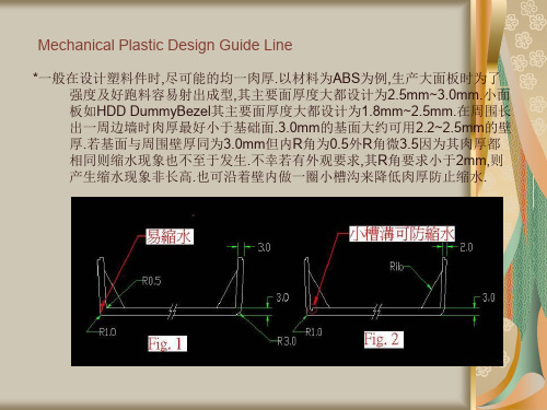
Mechanical Plastic Design Guide Line
一般在设计塑料件时,尽可能的均一肉厚.即使要改变厚度也要缓和进方 式,避免急速,忽然的变化,会在另一边的平面造成应阴影.
Mechanical Plastic Design Guide Line
*一般在设计塑料件时,尽可能的均一肉厚.在平面上多出的厚度会在凸出物的背面 造成缩水的凹陷.为避免此情形可将凸出物视设计功能改成肋状(Rib),其Rib 宽度也勿大于肉厚的1/2.
Mechanical Plastic Design Guide Line
*一般在面板上都会有一些指示灯(LED Lens),运用导光柱(Lens)将机壳内Control board上LED的光引导至面板使操作者可清楚使用状况.建议--在设计时將 Lens凸出面板0.2~0.5mm.一則:若设计时是将Lens与面板平齐,由于组装的 公差,有可能有些Lens会凹陷不在与面板同一平面上而影响外观.若设计为 些许的凸出时,即使有组装的公差也较不会造成内凹现象. 二則:Lens些许的凸出时即使在侧面也较容易看到亮灯的情形.
Mechanical Plastic Design Guide Line
老外精心总结的塑料件设计提要

parison of materialsPlastic is not metalComparison of materials –Many plastic designs still continue to be derived from“metal parts”. In the series commencing here the authors set out to describe the points that require attention when designing in plastics rather than traditional materials.Different basic material characteristicsThe properties of plastics materials can vary over a far wider range than all other engineering materials. Through the addition of fillers/reinforcing materials and modifiers the property profile of virtually any base polymer can be radically altered. Most basic properties of plastics, however, form a marked contrast to those of metals. For example, in a direct comparison, metals have higher– density– maximum service temperature – rigidity/strength– thermal conductivity and – electrical conductivity,while the– mechanical damping – thermal expansion – elongation at break and – toughnessof engineering thermoplastics are greater by orders of magnitude (see Fig. 1). To produce functional parts in plastic and at the same time save costs, radical design modification is generally necessary if the plastic is being used to replace metal. This process affords an opportunity for complete redesign of the component with possible integration of functions and geometric simplification.T OP T EN D ESIGN T IPS – A S ERIES OF 10 A RTICLESBy Jürgen Hasenauer, Dieter Küper, Jost E. Laumeyer and Ian Welshparison of materials2.Material selection3.Wall thickness4.Ribbing5.Gate positioning6.Cost-saving designs7.General assembly technology 8.Welding technology 9.Tolerances 10.Check listFig. 1Snap-fit hooksEncapsulationof metal insertsPipes underinternal pressureBellowsAirbag coverDifferent material behaviourPlastics sometimes exhibit completely different behaviour to that of metals under the same service conditions. For this reason, a functionally efficient, economic design in cast metal can easily fail if repeated in plastic with excessive haste. Plastics designers must therefore be familiar with the properties of this group of materials.Temperature and time dependence of deformation characteristicsThe nearer the service temperature of a material is to its melting point, the more the material’s deformation behaviour will be temperature- and time-dependent. Most plastics exhibit a change in their basic mechanical properties at room temperature or on exposure to short-term stress. Metals, on the other hand, usually display largely unchanged mechanical behaviour right up to the vicinity of their recrystallization temperature (> 300 °C).If the service temperature or deformation rate is varied sufficiently, the deformation behaviour of engineering thermoplastics can change from hard and brittle to rubbery-elastic. An airbag cover, for example, in its particular application involving explosive opening, exhibits completely different deformation behaviour from that of a slowly assembled snap-fit element made of the same material (Fig. 2). Similarly, this snap-fit element has to be assembled in a different way according to whether the temperature conditions are hot or cold. The effect of temperature here is significantly greater than the effect of loading rate.Degree of crystallization Processing conditions (material degradation)To demonstrate these effects, test bars were milled from injection moulded sheets in the longitudinal and transverse directions and their mechanical property values were compared in a tensile testing machine (Fig. 4).In the case of 30% glass-fibre-reinforced PET, there was a strength loss transverse to the direction of flow of 32% for tensile strength, 43% for flexural modulus and 53% for impact strength. These losses must be taken into account in strength calculation by incorporating safety factors.A wide variety of reinforcing materials, fillers and modifiers are added to many different thermoplastics to alter their property profiles. In material selection, the changes in properties produced by these additives must be checked very carefully in brochures or databases (e.g. Campus) or, better still, technical advice should be sought from specialists employed by the raw material manufacturers (Fig. 5).Effect of moistureSome thermoplastics, especially PA6 and PA66, absorb moisture. This may have considerable effect on their mechanical properties and dimensional stability. Particular attention should be paid to this property in material selection (Fig. 6-7).Other selection criteriaOther requirements relate to processing considerations and assembly. It is also important to investigate the possibility of integrating several functions in one component so saving costly assembly operations. This measure can have a very beneficial effect on production costs. It can be seen that in price calculations, it is not only the raw material price that is important. It should also be noted that materials with higher rigidity permit thinner walls and so result in faster cycles.It is important to list all the criteria for material selection and evaluate them systematically.A rough material selection flow chart is shown in Fig. 8.Fig. 63.Wall thicknessAs much as necessary – as little as possibleWall thickness –In designing components made from engineering plastics, experience has shown that certain design points arise time and again, and can be reduced to simple design guidelines. One such point is wall thickness design, which has an important influence on component quality.Effect on specific component criteriaChanging the wall thickness of a component has a significant effect on the following key properties:–component weight–achievable flow lengths in the mould –production cycle time of the component –rigidity of the moulded part –tolerances–quality of the component in terms of surface finish, warpage and voids.Ratio of flow path to wall thicknessAt an early design stage, it is important to review the question whether the required wall thicknesses can be achieved with the desired material. The ratio of flow path to wall thickness has a critical influence on mould cavity filling in the injection-moulding process. If long flow paths combined with low wall thickness are to be achieved in an injection mould, only a polymer with relatively low melt viscosity (easy-flowing melt) is suitable. To gain an insight into the flow behaviour of polymer melts, flow lengths can be determined using a special mould (Fig. 1-2).Flexural modulus as a function of wall thicknessThe flexural rigidity of a flat sheet is determined by the material-specific elastic modulus and the moment of inertia of the sheet cross section. If wall thickness is automatically increased to improve the rigidity of plastic components without any thought given to the consequences, this can very often lead to serious problems with partially crystalline materials. In the case of glass-fibre-reinforced materials, changing the wall thickness also influences the orientation of the glass fibres. Close to the mould wall, the fibres are oriented in the direction of flow. On the other hand, in the centre of the wall cross section, random fibre orientation occurs as a result of turbulent flow.By increasing wall thickness, it is mainly the cross-sectional area of randomly oriented glass fibresparison of materials2.Material selection3.Wall thickness4.Ribbing5.Gate positioning6.Cost-saving designs7.General assembly technology 8.Welding technology 9.Tolerances 10.Check listGatehigh melt viscositymedium melt viscositylow melt viscositythat is enlarged. On the other hand, the thickness of the zone in which the fibres are oriented in the direction of flow remains largely the same (Fig. 3).This boundary zone, which critically determines component rigidity in the case of glass-fibre-reinforced plastics, is thus reduced in proportion to the overall wall thickness. This explains the decline in the flexural modulus (Fig. 4) when wall thickness is increased. The strength values determined on standard test bars (3,2 mm) are not therefore directly applicable to wall thicknesses deviating from this. To estimate component behaviour, it is essential to make use of safety factors. So by increasing wall thickness without consideration of the consequences, material and production costs are increased without a significant improvement in rigidity.Increase wall thickness?An increase in wall thickness not only crucially determines mechanical properties but also the quality of the finished product. In the design of plastics components, it is important to aim for uniform wall thickness. Different wall thicknesses in the same component cause differential shrinkage which, depending on component rigidity, can lead to serious warpage and dimensional accuracy problems (Fig. 6). To attain uniform wall thickness, thick-walled areas of the moulding should be cored (Fig. 5). In this way it is possible to prevent the risk of void formation and reduce internal stresses. Furthermore, the tendency to warp is minimized. V oids and microporosity in the component severely reduce its mechanical properties by cross-sectional narrowing, high internal stresses and in some cases notch effects.S 1 > S 0s 1s 1 > s 0s 0Fig. 3Fig. 4Fig. 5Fig. 64.RibbingOptimum rib designRibs –To overcome the problems that can arise with thick walls, ribs are an effective means of increasing rigidity while allowing wall thickness to be reduced.Generally, the rigidity of a component can be increased the following ways: –increasing the wall thickness–increasing the elastic modulus (e.g. by increasing reinforcing fibre content)–incorporating ribs into the design.If the required rigidity cannot be achieved in a design, the recommended next step is to choose a material with a higher elastic modulus than the original material. A simple way to increase the elastic modulus is to increase the content of reinforcing fibre in a polymer. However, given the same wall thickness, this measure produces only a linear increase in rigidity. A much more efficient solution is to increase rigidity by providing optimally designed ribs. Component rigidity is improved as a result of the increase in the moment of inertia. For optimum dimensioning of ribs, it is generally necessary to take into account not only engineering design considerations as such but also technical factors relating to production and aesthetic aspects.parison of materials2.Material selection3.Wall thickness4.Ribbing5.Gate positioning6.Cost-saving designs7.General assembly technology 8.Welding technology 9.Tolerances 10.Check listOptimum rib dimensionsIn rib design, a large moment of inertia can most easily be achieved by providing high, thick ribs. However, with engineering thermoplastics, this approach usually creates serious problems such as sink marks, voids and warpage. Furthermore, if rib height is too great, there is a risk that the rib structure will bulge under load. For this reason, it is absolutely necessary to keep rib dimensions within reasonable proportions (Fig. 1).To ensure trouble-free ejection of the ribbed component, it is essential to provide a demoulding taper (Fig. 2).Restricting material accumulationFor components requiring a very high quality surface finish, such as hub caps, rib dimensioning is important. Correct rib design reduces the tendency to form sink marks and thereby increases component quality.Material accumulation at the rib base is defined by the imaginary circle drawn in Fig. 1. By adhering to the dimensional proportions recommended there, this “circle” can be made as small as possible and sink marks can be avoided or reduced.If the imaginary circle is too large in this area of material accumulation, voids can be formed and mechanical properties drastically lowered as a result.Stress reduction at the rib baseIf a ribbed component is exposed to applied loads, stresses may be created at the rib base. If no fillet radii are provided in this area of the component, very high stress concentration peaks will build up (Fig. 3), which not infrequently lead to cracking and failure of the component. The remedy is to provide a sufficiently large fillet radius (Fig. 1) that will permit better stress distribution at the rib base. Radii which are too large, on the other hand, will also increase the diameter of the imaginary circle, which in turn can lead to the problems already mentioned.Choice of rib structureIn plastics design, a cross-ribbed structure has proved successful because it can handle many different loading permutations (Fig. 4). A cross-ribbed structure correctly designed for the anticipated stresses ensures uniform stress distribution throughout the moulding. The nodes formed at the rib intersections (Fig. 5) represent material accumulations but can be cored to prevent any problems. Care should also be taken to ensure that undue material accumulation is avoided at the point where the rib joins the edge of the component (Fig. 6)5.Gate positioningCorrect gate locationGate positioning –Besides causing processing problems, the wrong choice of the type of gating system and gate location can have a considerable effect on the quality of a moulded part. Design departments should, therefore, not underestimate the importance of gate location.Apart from carrying out design calculations for plastics parts, designers must pay particular attention to mould gating. They have to choose the correct gating system and the number and location of gating points. The different types of gate and gating locations can have a considerable effect on part quality.parison of materials2.Material selection3.Wall thickness4.Ribbing5.Gate positioning6.Cost-saving designs7.General assembly technology 8.Welding technology 9.Tolerances 10.Check listFixing the gate location also determines the following characteristics of a plastics part:–filling behaviour–final part dimensions (tolerances)–shrinkage behaviour, warpage–mechanical property level–surface quality (aesthetic appearance).Moulders have little scope to rectify the undesirable consequences of incorrect gating by optimizing processing parameters.Orientation determines part propertiesIn the injection moulding process, the long polymer molecules and fibrous filling and reinforcing materials are oriented mainly in the direction of flow of the polymer melt. This results in directional dependency (anisotropy) of the part’s properties. For example, strength properties in the flow direction are considerably higher than in the transverse direction (Fig. 1). Here the influence of the reinforcing fibres is significantly greater than the effect on strength of molecular orientation alone. Fibre orientation also causes differential shrinkage in the longitudinal and transverse directions, which can lead to warpage.Quality reduction as a result of weld lines and trapped airWeld lines occur when two or more melt streams unite in the mould. This happens, for example, when the melt has to flow around a mould insert or when parts are gated at several points (Fig. 2a+b). In addition, different wall thicknesses in a part can also lead to separation of melt fronts and so cause weld lines. Air entrapment (air bubbles) occurs when air that should be expelled from the mould is enclosed by melt streams and cannot escape. Weld lines and air entrapment are often manifested as surface defects. Apart from the fact that they are ugly, as a rule they also considerably reduce the mechanical properties in the affected areas, particularly impact strength (Fig. 3-4).defective partUnsuitable gate positioning has adverse consequencesAs gates always leave obvious marks, they should not be placed in areas which should have a high surface quality. In any gating region, high material stress (shear) takes place that considerably reduces the property levels of the plastics resin (Fig. 5). Unreinforced plastics have higher weld line quality than reinforced plastics. The quality-reduction factors in the weld line area are highly dependent on the type and content of filling and reinforcing material. Similarly, additives such as processing aids or flame retardants can have a detrimental effect. It is therefore difficult to estimate how much these factors will affect the part’s final strength. In addition, weld line areas with high load-bearing capacity under tensile stress do not show equally good impact strength or fatigue endurance. With fibre-reinforced materials, fibres in the weld line area are aligned transversely to the direction of flow. This significantly lowers the mechanical properties of the part at this point (Fig. 6).Fig. 3020*********%5-6040-900-1530-7020-8050-80Fig. 4Correct gate positioningComplex mouldings usually cannot be produced without weld lines. If the number of weld lines cannot be reduced, they should be placed in non-critical parts of the moulding in terms of surface quality and mechanical strength. This can be done by moving the gate location or by increasing/reducing part wall thickness.Basic design principles:–do not gate parts in highly stressed zones –avoid or minimise weld lines–avoid leaving weld lines in highly stressed areas–with reinforced plastics, gate location determines part warpage –avoid air entrapment by providing adequate vents.Fig. 6gatevoid6.Cost-saving designsLow-cost designsPrice as a Design Factor –The designer of a plastics component bears a large part of the responsibility for its final cost. His decisions essentially predetermine the costs of production, mould-making and assembly. Correction or optimization at a later stage is generally costly or impracticable.Influencing cost through material propertiesTaking full advantage of specific properties of plastics materials can help to save costs in many ways:Designs with multiple integrated functionsReduction in the number of individual parts through integration of several functions in one e of low-cost assembly techniquesSnap-fits, welded assemblies, riveted assemblies, two-component technology, etc.Exploitation of dry-running propertiesSaves the need for additional or subsequent lubrication.Elimination of surface treatmentsIntegral colour, chemical and corrosion resistance, electrical and thermal insulation properties.NucleationMaterials in the same product family can have different cycle times. The reason for this is a nucleating additive that accelerates crystallization of the melt during the cooling phase.parison of materials2.Material selection3.Wall thickness4.Ribbing5.Gate positioning6.Cost-saving designs7.General assembly technology 8.Welding technology 9.Tolerances 10.Check listInfluencing cost through finished-part designFurther cost reductions can be achieved, over and above those mentioned above, by observing the following points:Wall thicknessOptimized wall thickness distribution influences material costs and can reduce production time. MouldsTwo-plate moulds, reduction in the number of splits, etc.TolerancesExcessively high tolerance requirements increase the reject rate and quality control costs. MaterialsReducing cycle and cooling times through the choice of materials that set up rapidly, minimizing warpage problems by using low-warpage polymers (e.g. optimization of the ratio of mineral to glass-fibre reinforcement).Cost comparison broken down according to production cost componentsInjection-moulded parts should be ready for assembly as soon as they are ejected from the moulding machine, without needing any additional finishing operations. If finishing operations are required, the cost of plastics components often reaches that of metal designs (Fig. 1).Design determines production costsA general increase in wall thickness will not always lead to the desired strength increase in a component, but it will certainly mean a steep rise in production and material costs (Fig. 2). Partially crystalline thermoplastics undergo volume shrinkage as they set up. This shrinkage must be compensated for by continuing melt feed during the holding pressure phase. The approximate holding pressure time per mm wall thickness is, for example:–POM = 8 s–PA66 unreinforced = 4-5 s–PA66 reinforced = 2-3 s(Applies up to wall thickness of 3 mm)Examples of typical applicationsIn contrast to metal designs, which have to be machined and often pass through many assembly stages to turn out a single functional part, plastics technology offers considerable savings potential. In this example (Fig. 3), the guide and drive rods, spring, barbed-leg snap-fit element and bearing arrangement are injection-moulded in one piece. The equivalent metal design would require not only five individual parts that have to be assembled, but the rod would also need lubrication where it comes into contact with the stop. Choice of a POM homopolymer in fact made lubrication unnecessary at this point, too.Barbed-leg snap-fit designs in combination with integral hinges reduce the number of individual components, thus making assembly easier and thereby lowering costs. If brittle materials are used, another barbed-leg snap-fit element takes over the locking function if the integral hinge breaks (Fig. 4). In designing the part, the designer also necessarily defines the design of the mould cavity. He therefore determines the ejection system and the number of splits required. By judicious arrangement of undercuts, splits can be replaced by cores (Fig. 5).Fig. 3Fig. 4Fig. 5Fig. 1Snap-fit Assembly DesignThe great advantage of snap-fits is that with this technique no additional elements are needed to make the assembly.The most commonly used types of snap-fits in plastics technology are:–barbed-leg-type snap-fits–cylindrical snap-fits–ball-and-socket snap-fits.With all these snap-fit designs, designers must ensure that the geometry of the assembly allows the components to be as stress-free as possible after assembly to avoid stress relaxation, which would loosen the assembly with time.Basic design principlesThe design of a snap-fit assembly is determined by the permissible strain of the material to be used. Care should be taken with polyamide, for example, because in the dry state this material generally permits considerably lower strains than in the conditioned state. Glass fibre content also has an important effect on the permissible strain of the material and thus also on the permissible deflection of the barbed leg (Fig. 1).In a barbed-leg-type snap-fit, tapering of the deflecting leg reduces stress (Fig. 2). This design allows better stress distribution over the entire bending length. Stress concentration peaks at the base of the leg are less and assembly forces are considerably reduced.Failure to radius the junction between the base of the barbed leg and the main body of the component, or to provide sufficiently large radii in this area, often results in weak points. In principle, a sufficiently large radius should be provided to avoid stress concentration peaks. Cylindrical and ball-and-socket-snap-fits often have to be slotted to facilitate assembly; in this case the slot end must not be designed with a sharp edge.Press-fit AssembliesPress-fits enable high-strength assemblies to be made between plastic components at minimal cost. As with snap-fit assemblies, the pull-out force of a press-fit assembly decreases with time as a result of stress relaxation (Fig. 3). Design calculations must take this into account. In addition, tests with the expected service temperature cycles must be carried out to confirm the feasibility of the design.Threaded Assemblies Array Threaded assemblies can be produced with thread-cutting orthread-forming screws, or by the use of integrally mouldedthreaded inserts. The flexural modulus of the material to beused provides a good guide to the type of threaded assemblythat is most appropriate. For example, up to a flexural modulusof about 2800 MPa, thread-forming screws may be used.Metal inserts must be used if metric screws are required or ifthe threaded assembly is intended to be undone several times.To prevent premature component failure, it is important toensure correct dimensioning of the boss (Fig. 4). Screwmanufacturers give recommendations on this.Screws with a tapered countersunk head should as a generalrule be avoided in plastics assembly technology since theresulting forces (Fig. 5) cause the screw hole to “splay out”.One possible result of such additional stress is that weld linescan easily rupture.8.Welding technologyThe Best Assembly Techniques –Part IIWelding technology – In addition to the assembly techniques described in article 7 of this series, many different welding methods can be used to join plastic parts. To ensure low-cost, functionally efficient designs, it is necessary to select a suitable welding method and give careful thought to the required joint geometry at an early stage in the design process.parison of materials2.Material selection3.Wall thickness4.Ribbing5.Gate positioning6.Cost-saving designs7.General assembly technology 8.Welding technology 9.Tolerances 10.Check listair-intake hose (inserts)air-intake pipebodyrunner jointscigarette lighterFig. 1Welded joints are assemblies for permanently connecting plastics parts without additional assembly elements. The choice of welding method depends on several criteria: the geometry of the moulded part and on the materials used, on cost-effectiveness, suitability for integration into the overall production cycle and the mechanical and aesthetic quality requirements for the assembly zone. Different welding methodsThere are many different, cost-effective welding methods suitable for industrial mass production. The methods most frequently used for plastics engineering components are (Fig. 1):–hot-tool welding–spin welding–vibration welding–ultrasonic welding.Other methods worth mentioning include:–high-frequency welding–induction welding–hot-gas welding.New methods are also being developed (e.g. laser welding), but these are not yet widely used in industry.In all these methods, the assembly operation is carried out by applying heat (melting the surfaces to be joined) and pressure. Heat can be generated directly by contact or radiation, or indirectly by internal or external friction, or by electrical effects.Choosing the right methodTo achieve good, reproducible weld quality, it is necessary to choose a suitable welding method, optimize welding parameters and ensure that the parts to be assembled are correctly designed for the welding method being used. Welding machinery manufacturers supply not only standard equipment but also various special welding units to cater for a wide variety of welding tasks. Before deciding on a welding method, it is advisable to consult the machinery manufacturers or resin suppliers. Different welding propertiesTheoretically, all thermoplastics are weldable, but the welding behaviour of plastics differs considerably in some cases. Amorphous and semi-crystalline polymers cannot be welded together. Plastics that absorb water (e.g. nylon) need to be pre-dried, since moisture leads to poor-quality welds. For best results, nylon parts should either be welded immediately after injection-moulding or kept in a dry state before welding. Resin additives such as glass fibres and stabilizers can also influence welding results. Welded assemblies of unreinforced plastics can attain weld factors close to the strength of the parent material, given suitable process parameters and part design. With glass-fibre-reinforced plastics, loss of strength due to fibre separation or reorientation in the welding zone must be taken into account.Correct weld designAn essential requirement for high-quality welds is suitable design of the weld profile. The profiles shown in Figures 2 and 3 have proved successful basic designs. If the weld zone additionally has to meet high aesthetic specifications, then special geometry is needed. The diagrams show possible ways of hiding flash by providing recesses to absorb the excess material (Fig. 4). Thin-walled parts need to be designed with a guided fit into each other, so that the necessary welding pressure can be applied without the walls moving out of alignment.。
塑料模设计与制造指导手册范本
(部讲义)编著:兆飞审核:模具教研室铁路职业技术学院机械与电子工程学院模具教研室目录第一单元热塑料制品设计原则 (4)一、尺寸、精度及表面粗糙度 (4)1、尺寸 (4)2、精度 (5)3、表面粗糙度 (6)二、形状 (6)三、脱模斜度 (7)四、壁厚 (8)五、加强筋 (8)六、支承面 (9)七、圆角 (10)八、孔(槽) (10)九、螺纹 (11)十、嵌件 (13)十一、标记、符号、图案、文字 (15)第二单元塑料模设计原则与查验 (17)一、塑料模具设计原则 (17)1、模具设计上应与热交换器相似 (17)2、采用平衡式流道系统 (18)3、模具设计标准化 (18)4、足够的排气装置 (18)5、确保快速修模,设计时预留修模量 (18)6、以容易组立,不易出错为原则 (18)7、以模具易加工,精度适当为原则 (18)二、模具设计要项查检 (19)(一)注塑模具设计之计算公式 (19)(二)注塑模具结构设计 (20)第三单元塑料模具设计流程 (23)一、方框图 (23)二、流程表 (24)第四单元塑胶模具制作规 (28)一、确认图面 (28)二、模具制作流程 (29)三、试模前务必完成下列之确认 (29)第五单元注射模设计实例 (31)一、注射成型工艺规程的编制 (31)1、塑件的工艺性分析 (31)2、计算塑件的体积和重量 (32)3、塑件注射工艺参数的确定 (32)二、注射模的结构设计 (32)1、分型面选择 (32)2、确定型腔的排列方式 (33)3、浇注系统设计 (33)4、抽芯机构设计 (34)5、成型零件的结构设计 (34)三、模具设计的有关计算 (34)1、型腔和型芯工作尺寸计算 (35)2、型腔侧壁厚度和底板厚度计算 (35)四、模具加热与冷却系统的设计 (37)五、注射机有关参数的校核 (38)六、绘制模具总装图和非标零件工作图 (38)第六单元模具制造实例 (41)一、模具总体工艺流程图 (41)二、注射模主要零件加工工艺规程的编制 (42)三、模具装配工艺流程编制 (43)四、模具试模、调试与验收 (45)1 试模的目的与要求 (45)2 塑料模具的试模与调整 (46)3、塑料注塑模具的验收 (54)《塑料模具设计》课程设计指导书 (56)第一章概论 (57)一、课程设计的目的 (57)二、课程设计的选题 (57)三、课程设计基本要求 (57)四、设计前的准备工作 (57)五、设计步骤及注意事项 (58)六、设计任务 (58)七、设计参考资料 (58)八、设计时间及学时安排 (58)第二章注射模具的设计程序 (59)一、接受任务书 (59)二、收集整理资料 (59)三、注射成型制品的分析 (59)1、消化塑料制件图 (59)2、塑料成型工艺分析 (59)3、明确制品的生产批量 (59)4、计算制品的体积和重量 (60)四、选择成型设备 (60)五、拟定模具结构方案 (60)六、绘制模具装配图和零件图 (60)七、校核模具图样 (60)八、编写模具设计计算说明书 (60)第三章注射模具设计及模具图绘制 (61)第一节模具结构设计 (61)一、模具的基本结构 (61)二、注射模具设计的基本容 (61)三、注射模具设计的有关计算 (62)四、模具零部件的设计 (62)第二节模具图的绘制与校核 (62)一、装配图要求及绘制方法 (62)二、零件图要求及绘制 (64)三、审核设计结果 (65)第四章模具设计计算说明书的编写 (66)一、设计计算说明书的容 (66)二、设计计算说明书的要求及格式 (67)附件1:封面 (69)附件2:《塑料模具设计》课程设计任务书 (70)附件3:学院注塑机主要技术参数: (71)附件4:模具制造毛坯尺寸余量设计参考: (71)第一单元热塑料制品设计原则一、尺寸、精度及表面粗糙度1、尺寸这里的尺寸是指制件的总体尺寸,而不是壁厚、孔径等结构尺寸。
外国工程师传授的design资料

外國工程師傳授的design資料,供大伙儿享受。
Injection Molding Design Guidelines注塑模具设计指导Much has been written regarding design guidelines for injection molding. Yet, the design guidelines can be summed up in just a few design rules.已经有许多关于设计注塑模具的书了,可是设计准那么能够被归纳以下几点:Use uniform wall thicknesses throughout the part. This will minimize sinking, warping, residual stresses, and improve mold fill and cycle times.1.零件整体壁厚维持均匀.如此能够最小化缩坑,翘曲,强度减小,模具填充和循环时刻.Use generous radius at all corners. The inside corner radius should be a minimum of one material thickness.2.在转角处大量采纳圆角.圆角内部最小半径为一个壁厚.the least thickness compliant with the process, material, or product design requirements. Using the least wall thickness for the process ensures rapid cooling, short cycle times, and minimum shot weight. All these result in the least possible part cost.3.依照工艺,材料,产品设计需求.采纳最小壁厚.最小壁厚的应用能够确保外國工程師傳授的design資料,供大伙儿享受。
塑胶件设计准则(一)
塑胶件设计准则(一)随着塑料工业的迅速发展,塑胶制品已经成为生产制造业中不可或缺的一部分。
然而,在进行塑胶件设计时需要考虑多方面的因素,这些因素决定了产品的使用寿命、质量和成本。
本文将介绍塑胶件设计准则,以帮助读者更好地了解如何进行塑胶件设计。
1.材料选择在设计塑胶制品时,首先需要选择适合的塑料材料。
不同的材料具有不同的特性,例如抗拉强度、刚度、耐热性等。
选择材料的时候,需要考虑产品的使用环境和工作要求,以确保最终产品符合需求。
2.几何设计几何设计是塑胶制品成功的关键之一。
正确地设计产品的弯曲角度、半径和厚度等等是至关重要的,因为它们直接影响产品的可靠性和稳定性。
产品的自洁能力、防裂性和其它特性也与几何设计相关。
3.融合融合是塑胶件设计中的另一个关键因素。
在生产过程中,需要考虑良好的融合,这将直接影响产品的质量和强度。
一般来说,在处理过程中要确保塑料的速度和温度是恰当的,使产品外观平滑、无瑕疵,并且强度更加均匀。
4.尺寸精度产品的尺寸精度对于高质量的产品制造非常重要。
在设计和生产过程中,必须严格控制尺寸精度。
如果精度过低,往往会影响产品的可靠性和性能。
5.模具设计加工模具的质量将直接影响成品的质量。
因此,在设计模具时,需要充分考虑产品的要求,并尽可能减少缺陷的可能性。
从模具材料的选择到处理方法的选定,都必须被考虑到。
综上所述,塑胶件设计准则是非常重要的,可以确保产品质量和性能。
设计师需要仔细考虑产品使用的工作条件,选择适合的材料,并采取正确的几何设计方法。
保证良好的融合、尺寸精度和模具设计,可以使塑料制品达到最高质量标准,从而满足用户的需求。
塑胶产品设计designing with plastic
74
9.1.4 Assembly with Fasteners
75
9.1.4.1 Bolted Assembly
75
9.1.4.2 Threaded Metal Inserts
77
9.1.4.3 Self-Tapping Screws
78
9.1.4.4 Riveted Assembly
78
9.1.4.5 Sheet Metal Nuts
1
Physical Properties
and Terminology
2
Mechanical
Properties
3
Thermal
Properties
4
Electrical Properties
5
Environmental
Considerations
6
Structural
Analysis
7
Design Considerations for
1.
Plastics Materials – An Overview
10
1.1 Classification
11
1.1.1 Thermoplastics
12
1.1.2 Thermosets
12
1.1.3 Crystalline, Amorphous, and Liquid
13
Crystalline Polymers
13
1.1.4 Copolymers
14
1.1.5 Alloys
14
1.1.6 Elastomers
14
1.1.7 Additives, Reinforcements, and Fillers
《塑胶产品相关设计》讲义
Wall Thickness, Rib
Conventional
0.080 to 0.125 in (2.0 to 3.2 mm)
trib 0.6 twall h 4 twall r 0.375mm
1o 2
Thinwall:
0.050 to 0.080 in (1.2 to 2.0 mm)
(1.2 mm)
tboss 0.6 twall twall
h 4 twall
r 0.375mm 0.6 *twall
1o 2
1o
OD 2 ID
tboss twall h 4 * twall r 0.6 *twall
1o
OD 2 ID
壁厚設計 Wall Thickness Design
差 [Poor]
較好 [Better]
最好 [Best]
掏空設計(1) Coring Out Design (1)
原設計 [Original]
改進設計 [Improved]
掏空設計(2) Coring Out Design (2)
差 [Poor]
L H
A'
A'
KE
JD F
I
G
A C
B
Section A'-A'
A =凸轂附著處壁厚
wall thickness B =凸轂外環直徑
dia. of boss over radii C = 0.5 A D =2B E = 1 ~ 2 deg F = 0.13 mm ( radius ) G =D H = 0.8 A I =A/4 J =2B K = 0.3 ~ 1 J L = 0.5 A
第5部分:塑胶件设计指南
原始的设计
优化的设计
11
1.零件壁厚
C. 零件壁厚均匀
当壁厚不均匀时: 原始的设计
较好的设计a
较好的设计b
优化的设计
DFMA
12
2.避免尖角
A.避免零件外部尖角
DFMA
原始的设计
优化的设计
例外:零件分模线处直角的设计比较好
原始的设计
优化的设计
13
2.避免尖角
B.避免在塑胶熔料流动方向上产生尖角
39
8.提高塑胶件外观的设计
D.设计美工沟:
原始的设计 美工沟的设计之一 美工沟的设计之二
DFMA
40
8.提高塑胶件外观的设计
DFMA
E.避免外观零件表面出现熔接痕:
塑胶件表面咬花可以部分掩盖熔接痕,但并不能完全掩盖熔接痕; 喷漆可以掩盖熔接痕; 合理设置浇口的位置和数量,避免在零件重要外观表面产生熔接痕; 保证模具通风顺畅。
二.塑胶件设计指南
1. 零件壁厚 2. 避免尖角 3. 脱模斜度 4. 加强肋的设计 5. 支柱的设计 6. 孔的设计 7. 提高塑胶件强度的设计
DFMA
8. 改善塑胶件外观的设计 9. 降低塑胶件成本的设计 10. 注塑模具可行性设计
三.塑胶件的装配
1. 卡扣装配 2. 紧固件装配 3. 超声波焊接
分类非结晶塑胶结晶塑胶比重较低较高拉伸强度较低较高拉伸模量较低较高延展性较高较低抗冲击性较高较低最高使用温度较低较高收缩率和翘曲较低较高流动性较低较高耐化学性较低较高耐磨性较低较高抗蠕变性较低较高硬度较低较高透明性较高较低加玻璃纤维补强效果较低较高材料特性塑胶分类dfma一
DFMA
第5部分 塑胶件设计指南 Design for Plastic Guidelines
- 1、下载文档前请自行甄别文档内容的完整性,平台不提供额外的编辑、内容补充、找答案等附加服务。
- 2、"仅部分预览"的文档,不可在线预览部分如存在完整性等问题,可反馈申请退款(可完整预览的文档不适用该条件!)。
- 3、如文档侵犯您的权益,请联系客服反馈,我们会尽快为您处理(人工客服工作时间:9:00-18:30)。
7
Gate Location & Shrinkage
Mineral Reinforced
Flow Direction
Gate
Transverse Direction
Mineral Resists Shrinkage More Uniformly in All Directions
23 C, 50% RH
180 160 140 120 100 80 60 40 20 0
Flow Direction Knit Line
MPa
ZYTEL 70G33
MINLON 22C
RYNITE 530
Engineering Polymers / DuPont (Korea) Inc.
29
Weld Line & Strength
Design Guidelines
Version 1.0
Nov . 24 . 2004 Technical Center / Engineering Polymers DuPont (Korea) Inc.
Engineering Polymers / DuPont (Korea) Inc.
1
Design Flow
Sizing to Reduce Warpage
Bow-In
Max R
T 2 T
Reduce Stress Conc.
Reduce Warpage
Engineering Polymers / DuPont (Korea) Inc.
21
Shrinkage & Warpage Non-uniform Wall Thickness Contributes To
Follows
Inside Radius
Engineering Polymers / DuPont (Korea) Inc.
23
Good Design
Gate Bad 3T Gate Better T
Best
Engineering Polymers / DuPont (Korea) Inc.
24
Shrinkage & Warpage
31
Weld Line & Strength
Weld Line
Gate
Engineering Polymers / DuPont (Korea) Inc.
32
Weld Line & Strength
Improved Design
Weld Line
Gate
Engineering Polymers / DuPont (Korea) Inc.
Tensile Strength ZYTEL 70G33 23 C, DAM Engineering Polymers / DuPont (Korea) Inc.
4
Gate Location & Shrinkage
Flow Direction
Gate
Transverse Direction
Material Flow Affects Orientation
Engineering Polymers / DuPont (Korea) Inc.
8
Shrinkage & Warpage
Shrinkage Increases with Wall Thickness
Higher Shrinkage
Lower Shrinkage
9
Engineering Polymers / DuPont (Korea) Inc.
Design Concept
CAE
CAD
Engineering Polymers / DuPont (Korea) Inc.
2
Typical Wall Thickness
For Engineering Polymers
millimetric scale
0
1 2
3
4 5
6
7
General applications
11
Shrinkage & Warpage
Good Flatness
Engineering Polymers / DuPont (Korea) Inc.
12
Shrinkage & Warpage Case on a ‘plate + rib’ profile
b a Gate L Gate h
w
Flow angle
17
Shrinkage & Warpage Glass reinforced materials
Gate
Engineering Polymers / DuPont (Korea) Inc.
18
Shrinkage & Warpage
Effect of Machine Settings on Shrinkage
15
Gate Location & Shrinkage
Bad Gate Location
Gate
Engineering Polymers / DuPont (Korea) Inc.
16
Gate Location & Shrinkage
Flow Steps
Engineering Polymers / DuPont (Korea) Inc.
Engineering Polymers / DuPont (Korea) Inc.
5
Gate Location & Shrinkage
Unreinforced
Flow Direction
Gate
Transverse Direction
Higher Shrinkage in Direction of Molecular Orientation/Flow
38
Good Design, Strength
1X
Relative Torsional Stiffness
Engineering Polymers / DuPont (Korea) Inc.
1.5X
13.3X
27X
30X
39
Bad & Good Design, Example
Engineering Polymers / DuPont (Korea) Inc.
1.5
1.0 0 0.2 0.4 0.6 0.8 R/T 1.0 1.2 1.4
26
Engineering Polymers / DuPont (Korea) Inc.
Sharp Corners
SHARP CORNERS
Engineering Polymers / DuPont (Korea) Inc.
Cooling Side to Side
HOT
COOL
PART
TOOL
Engineering Polymers / DuPont (Korea) Inc.
25
Sizing to Reduce Stress Concentration Factor (SCF)
Stress Concentration Factor 3.0 2.5 2.0 P = Applied Load R = Fillet Radius T = Thickness
Mat erial Type
Filler Type
Tensile % St rengt h MPa R et ained One Two Gat e Gat e
N ylon 66 N ylon 66 Polyprop Polyprop
N one 40% Glass N one 30% Glass
79 199 37 69
Shrinkage (S)
SThin Sin flow
S Thick S
1 1.5 2
3
4
Wall thickness [mm]
14
Engineering Polymers / DuPont (Korea) Inc.
a
Shrinkage & Warpage Unreinforced materials
33
Sinks
Ribs and Sinks
Engineering Polymers / DuPont (Korea) Inc.
34
Sinks
Ribs and Sinks
T
0.5 T (max. 0.75T)
R=T
3T
R max. 0.5T
D1
T
D2
Sink mark
should be improved
40
Bad & Good Design, Example
Isochrones
Engineering Polymers / DuPont (Korea) Inc.
13
Shrinkage & Warpage Glass reinforced materials
Deformation trend b
Shrinkage [%]
Transverse to flow In flow
better
35
Engineering Polymers / DuPont (Korea) Inc.
Sinks
Sink
Improved Sinks
Grained or Stippled Surface
Tooled Depression
Offset at Rib