60t移车台使用说明书
移动式升降平台说明书

前言非常感谢您对我公司的信任!从今天起您已成为我们的优级服务对象。
我们将竭诚为您提供技术咨询、工程方案、设备使用、维护等服务。
为使您的设备性能得到充分发挥,我们建议您在使用本机之前抽点时间通读一遍此使用说明书,这样做可使您更好的掌握本机的使用要点,从而使您感觉到本机优越性能给您带来的方便。
您将会发现,我们在设计、制造工艺、方便操作及实用性等方面,均为满足顾客的要求而做出了各种探索。
请检查任何搬运损坏的可能性,如果您的装置有损坏或不能操作,请立即通知销售商或我公司。
如果装置直接运到您处,请尽快与装运公司联系,因为只有收货人才有权利就搬运损坏问题向承运者提出赔偿。
本厂生产的SJY、SJG、SJZ、SJD等系列液压升降机械广泛应用于建筑、工矿、车站、码头等场所,是一种操作方便、移动灵活的机械工具。
并且,本产品经多年演变和制造商的不断改进已深入应用到了重载、汽车工业、流水线、旋转舞台等领域,越来越成为各行业不可或缺的使用工具。
欢迎光临我公司参观、指导,并衷心恳求您为我们的工作提出宝贵意见,以便今后为您更好的服务。
一、产品外型图(图1)756431.支腿 2.底盘3.电动机4.操作屏5.油缸6.臂架7.工作台二、产品的主要用途产品型式我公司生产的液压升降台共有:SJY剪叉移动式液压升降平台SJG固定式液压升降货梯SJD导轨式升降平台SJYC-QG系列高空作业平台SJYL铝合金升降平台TG套缸式液压升降平台SJW系列升降舞台KP系列电动平车以上每种型号可根据负载、行程、工作台尺寸、动力装置等不同的组合,扩展为几十种规格。
三、产品的主要结构和系统说明SJY型移动式升降平台一般有四大系统构成,即机械结构系统、液压系统、电气系统和移动系统;固定式液压升降货梯除了没有移动装置外,其它基本一样。
油泵和电动机组成动力单元。
高起升移动式升降台为内置式动力单元;固定式升降货梯一般为外置动力单元。
1、主要结构升降平台的机械结构一般由底座、臂架和工作台三部分组成。
商业平台梯型平台搬运设备说明书

H I G H L A N D E R Commercial Platform LiftCPL400CPL600CPL800CPL1000CPL1200CPL1400Table of ContentsInstalling the liftUsing the Manual 2 When You Receive the Lift 3 Specifications 3 Safety 3 Code Requirements 4 Site Requirements 4 Required Tools 4 Required Materials 4 Preparing to Install the Lift 5 Controller Harness Connections 5 Installing the platform 6 Installing the outer guard panel 7 Installing the fixed ramp 7Installing the folding ramp8 Anchoring the Lift 9 Setting the Limit Switches 10Verifying Operation of the Lift11 Manual Override 12 Call-Sends (optional) 12Top Landing Gate (optional)13 EMI and Flush Strike (optional) 14 Platform Gate (optional) 15Fascia Panel (optional)16 Owner’s Section 17 Safety 18 Controls 19Operating the Lift20 Warranty 22Using the ManualThis manual will provide step by step instructions on how to install and operate your lift. Read and understand the entire manual before beginning to install the lift.When You Receive the Lift• Check the lift for shipping damage. If you see any damage contact the freight carrier to file a damage claim.• Verify the products match that described on the packing list attached to the exterior packaging.• Verify the contents of the package match that shown below to the right.SpecificationsPayload Capacity 750 lbsVertical Travel 54” – 171”Height 77” – 197”Foot Print VARIESPlatform Size 36” x 54” / 36” x 60” / 42” x 60”Input Voltage 115vac - 20aControl Voltage 24vac or 24vdcPlatform Speed 10 ft/minMotor 1/2hp-90vdc or 1/2hp-24vdcSafety• Read all instructions in this manual before installing or operating the lift.• Do not exceed the maximum payload capacity of 750 lbs.• Do not ride on the lift until it is anchored in place.• This product is designed only for lifting people and wheel chairs. Do not use it for any other purpose. • Always wear eye protection while installing or servicing this product.• Always disconnect this product from the electrical source before servicing it.• Only use the fasteners supplied with this lift.• Do not wear loose clothing or jewelry when working on this product.• Do not disable any safety equipment or switches supplied with this lift.• Stay away from all drive train components while the lift is operating.Code RequirementsYour lift has been designed to meet ASME A18.1 section 2 and CSA B44/ASME A17.5, with the addition of certain options. Code requirements for Vertical Platform lifts vary depending on location. It is the installers responsibility to contact their local code enforcement office and determine all of the regulations they are subject to. You must do this before installing the Vertical Platform Lift.Site Requirements•The lift will require a 115vac 20amp grounded circuit.•Outdoor Installations will require a GFI protected circuit.•Only install the lift on a 4” thick , level 3,500 psi reinforced concrete slab.•Foot Print varies depending on platform size and options.Required tools•1/2" Hammer Drill•3/8" Masonry Drill Bit• Appliance Dolly• Hammer• Level• Measuring Tape•Socket Wrench SetRequired materials• 4 Floor anchorsHarmar recommends securing the lift using our Anchor Kit. If you purchase you ownfloor anchors they must use 3/8” bolts and have a minimum tensile strength of 6000 LBS.Preparing to Install the LiftFinal Site InspectionVerify the surface the lift will mount to is smooth and level. This surface must be made from 3,500 psi reinforced concrete with a minimum thickness of 4”.Verify that there is enough space for the lifts foot print. Be sure to include space neccesary for platform. Caution: Verify that the running clearance around the lift complies withany codes for your area.•The horizontal gap between the edge of the platform and the upper landing must no less than 3/8”and no greater than 3/4”.•The horizontal gap between the guard panel and any wall or barrier must be no less than 2” and no greater than 3”.•Verify that sufficient head room exists above the lift. The lift will require 6’ 8” of clearance above the platform floor when the lift is at the upper landing.Warning: The area between the floor where the lift is mounted and the toplanding must be covered by a smooth vertical fascia. This is to to eliminate any pinch points between the platform and landing.Connecting to ElectricityThe lift will require a 115 VAC 20 amp grounded electrical circuit.Depending on local codes, this connection may need to be routed in electrical conduit and hard-wired. Warning: Do not ride on the lift until it has been anchored in place.Controller Harness ConnectionsHigh VoltageCircuit Breaker (AC unit only)Low Voltage Circuit BreakerPlatformTraveling CablePhone JackConnectionSafety PanJumperUpper LandingInterlockLower LandingInterlockUpper & LowerCall‐SendsUpper & LowerLimit SwitchesBypass Switches(Strikes only)Installing the PlatformStep 1The mounting bolts, nuts and spacers thatsecure the platform to the lift carriage arepackaged in the small parts box. Begin bylocating these pieces and setting aside.Step 2Position the platform by aligning the supportlegs with the carriage flanges that protrudefrom the front cover.Step 3Align the four mounting holes and insert a ½”x 3” bolt into each hole. The upper holeshave a spacer that must be placed inbetween the carriagne flange and platformleg. Install the locknut on each bolt andtighten sufficiently (approx. 50 lb-ft.).Step 4Plug in the harness for the platform safetypan and unplug the safety pan jumper on thecontroller (ref pg 5). Secure the harnessesunder the clip on top of the carriage flange.Installing the Outer Guard PanelsStep 1Remove the hexbolts on the corners of the platform. Insert the guard panel posts into the pockets in the platform. The smooth side of the guard panels should face in towards the center of the platform.If you have a 90 degree exit platform, install the end guard panel using the provided bracket and bolt to inner guard panel.Step 2Install the platform control box on the rear guard panel using screws and nuts through the panel.Step 3Plug in the harness for the platform control box. Secure the harnesses under the clip on top of the carriage flange.Installing Fixed RampStep 1• Position the ramp after the lift is in its final location.• Maintain a gap of 3/8” to 3/4” between the ramp and platform.• Drill a pilot hole into the concrete andfasten using supplied concrete lags through ramp flanges.Installing Auto-folding Ramp (optional)Step 1Install the ramp roller guide on the side of thelift tower using the screws already installed inthe panels.Step 2Attach the two ramp pivot tabs to the lowerlanding sides of the platform. Reinsert thehex bolts, one of which will go through theguard panel post, and tighten.Step 3Attach the ramp to the pivot tabs usingshoulder bolts and locking nuts. Tighten thenuts until they seat against the bolt shoulder.Step 4Attach the ramp roller arm by bolting it to theunderside of the ramp.The ramp roller should align and makecontact with the ramp roller guide.Anchoring the LiftAnchorsHarmar recommends securing the lift using the concrete anchors provided. If youpurchase you own floor anchors they must be 3/8” minimum of sufficient length. All four floor anchors must be installed correctly in accordance to their instructions.Step 1• Position the lift in its final location.• Verify that it is level and perpendicular to its surroundings and all running clearances are the proper dimension. • Shim if necessary.Step 2Use the lift’s base as a template. Drill 4 holes into the concrete making sure that the holes are deep enough to accept the anchors.Tip: Concrete dust may have settled into the holes you just drilled. Use a shopvacuum to clean out these holes. This will ensure the floor anchors set correctly.Step 3Secure the lift in place by tightening the floor anchor bolts.Step 4 (800 or taller models)Taller lifts must have the top of the lift tower anchored into a solid surface to ensure running clearances remain constant.There are two options for anchoring the top of the tower:1) For lifts going up to a landing such as adeck or porch, the optional tower brace is the preferred method. Instructions for the brace are packaged with it.2) For lifts that are placed with the back ofthe tower against a solid wall such as inside of a hoistway, drilling two holes through the top tower cross brace and anchoring is preferred.9Anchor two locationsSetting the Limit SwitchesYour lift is equipped with upper and lower limit switches. The vertical location of these switches may be adjusted to fit your application. Typically the upper limit switch will need to be adjusted so the platform will stop level with the upper landing. The lower limit will typically not need adjusting.Step 1Verify the emergency switch is in the ON position. Run the lift in the up direction until the platform floor is level with the upper landing. Disconnect the lift’s power (at the building’s circuit breaker for AC units, at the battery box for DC units) before going to the next step.Warning: Moving components can cut and crush. Do not operate the lift if you are in close proximity to any drive components. Be aware that loose clothing or jewelry may catch on moving parts.Step 2Remove the screws at the top of the lift that attach the front cover.Step 3Remove the front cover by tilting it forward and lifting upwards. The bottom of the front cover sits on a pin on either side of the lift frame. Set the cover aside in a safe location where it will not get damaged. Step 4Loosen the bolts that attaches the upper limit switch assembly. Slide the assembly down the track until the lower switch in the assembly comes in contact with the lift’s car. You should hear the limit switch click as contact is made. Retighten the set screw fastening the limit switch assembly in place. Step 5Replace the front cover and secure it with the screws you removed in step 1.Step 6Re-connect the lifts electricial power at the circuit breaker. Verify that the emergency switch is in the on position.Step 7Run the lift in the down direction for several inches. Next, run the lift in the up direction. Continue to press the up button until the upper limit switch has caused the lift to stop. Verify that the platform has stopped level with the upper landing. If it has not, readjust the limit until it is level.10Verifying Operation of the LiftCaution: Complete the following section before training the customer to use the lift.Step 1Run the lift up and down for 5 complete cycles. Hold the direction button down and allow the limit switches to stop the lift. At the top, verify that the platform stops level with the upper landing. At the bottom, verify the access ramp (if equipped) unfolds and rests on the ground.Step 2Verify the operation of the Emergency stop switch. When this switch is pushed in the lift should not run in either direction. When this switch is turned and pulled back out, the lift should operate normally.Step 3Verify the operation of the sensor pan underneath the platform. Start with the lift at the top landing. Press up on the sensor pan. While holding the pan in this location, press the down switch on the platform. The lift should not run.Warning: Do not run the lift if anyone is under the platform.Manual OverrideYour lift is equipped with a manual handcrank, to be used in the case of a power failure.Step 1Before using the manual handcrank verify that it’s use is required. Check that the emergency stop switch is pulled out. Check that the electrical cord is connected to the supply. Also check that the buildings circuit breaker has not tripped. Try to run the lift by pushing both the up and down buttons. If the lift still will not run, complete the following steps:Step 2Disconnect the power from the lift. Warning: Do not service or operate the manual handcrank while the lift is connected to electricity.Step 3Remove the screws and remove the top cap at the top of the tower.Step 4Insert the manual handcrank into the opening on the top of the brake assembly. It may be neccesary to slightly rotate the handcrank until it fully seats down on the hex portion of the brake. Rotate the crank to raise or lower the platform. Call-Sends (optional)The optional Call-Send controls are to be used at the upper and/or lower landings to call the platform to you or send it to the other landing.They should be mounted on the wall at each landing at a convenient height. Consult local codes for placement with consideration to clearances.A length of multi‐conductor wire willneed to be ran from the bottom of the lifttower up to the landing Call‐Sends.Consult local codes for type andmounting requirements. After wiring iscompleted, the wiring harness must beplugged into it appropriate receptacle onthe controller (ref pg 5).Wiring ConnectionsCall‐Send Lift HarnessBlue BlueWhite WhiteRed RedTop Landing Gate (optional) The optional top landing gate is provided with a combination mechanical lock and electric contact (interlock).The interlock:•Prevents the lift from running if the gate is not closed.•Prevents the gate from being opened if the platform is not at the top landing.•Unlocks when the lift is on the upper limit switch.A crescent shaped key is provided to manually unlock the gate during installation. The key is inserted from the backside to lift up on the solenoid that holds the gatedlocked.Mount the gate by placing onto the upper landingmaking sure to align the gate opening with the platform (outer guard rail not shown for clearity).There are a number of attachment holes provided in the threshold portion of the gate for mounting using woodlag screws or concrete anchors as appropriate.Remove the latch post cover and connect the call-sendand interlock wire harnesses.The vertical posts of the gate must be attached to a supporting structure, (the gate is not designed to be freestanding). A length of multi‐conductor wire will need to be ran from the bottom of the lift tower up to the landing gate. Consult local codes for type and mounting requirements. After wiring is completed, the wiring harness must be plugged into it appropriate receptacle on the controller (ref pg 5).Wiring ConnectionsInterlock Harness Lift HarnessBlack BlackBlack GreenYellow WhiteYellow Orange*Blue* Brown*Must be tied togetherCall‐Send Harness Lift HarnessBlue BlueYellow WhiteRed RedEMI and Flush Strike Interlocks (optional)The optional EMI or Flush Strike Interlocks are provided with a combination mechanical lock and electric contact. They are to be used with existing doors. The interlock:• Prevents the lift from running if the door is notclosed.• Prevents the door from being opened if theplatform is not at the landing.A length of multi-conductor wire will need to be ran from the bottom of the lift tower to each interlock. Consult local codes for type and mounting requirements. After wiring is completed, the wiring harness must beplugged into it appropriate receptacle on the controller (ref pg 5).Flush Strike InterlockRefer to the instructions inside the strike box for mounting requirements.EMI Interlock1) Position interlock to door jamb and markmounting holes.2) Fasten Interlock to door jamb with #8 woodscrews.3) Route 4-conductor Interlock cable thru hole intop of interlock and make wire connections. 4) Attach door keeper and emergency key platesto hoistway door.EMI Interlock Wiring Connections EMI Lift Harness Black (A) Black Black (B) Green Yellow (C) White Yellow (D) Orange N/A Blue+ Flush Strike Interlock Wiring Connections For AC powered lifts Flush Strike Wires Rectifier Wires Lift Harness Wires Black ‐White Stripe Red Black ‐White Stripe Black Yellow BlackYellow Green* Yellow White Blue Orange Grey Blue Green Brown Red Red Black Black Yellow RedYellow Green* For Optional DC powered lifts Flush Strike Wires Lift Harness Wires Black ‐White Stripe Black Black ‐White Stripe Green* Yellow White Blue Orange Grey Blue Green BrownPlatform Gate (optional)The optional platform gate is provided with a combinationmechanical lock and electric contact (interlock).The interlock:•Prevents the lift from running if the gate is not closed.•Prevents the gate from being opened if the platform is not at the bottom landing.•Unlocks when the lift is on the lower limit switch.A crescent shaped key is provided to manually unlock the gate during installation. The key isinserted from the back side to lift up on the solenoid that holds the gated locked.Mount the gate by placing onto the lower landing side of the platform. There are a number of attachment holes along the bottom and up the sides of the gate frame to attach to the platform and guard panels.A wiring harness included on the gate will need to be routed along the gate frame, behind the rear guard panel and connected to it’s adjoining harness plug on the lift carriage. After wiring connection is made, the wiring harness must be plugged into it’s appropriate receptacle on the contoller (ref pg 5).Fascia Panel (optional)A fascia panel provides a smooth surface for the platform edge to run against to prevent any shear or obstruction hazards and must be utilized.A running clearance of no more than 3/4” and no less than 3/8” must be maintained between the edge of the platform and the fascia panel.Commercial Platform Lift - Owners SectionL Read the manual thoroughly before operating the lift.Congratulations on the purchase of your Harmar Vertical Platform Lift. This lift has been engineered to provide trouble free service for many, many years. Please read this manual completely before operating your lift.Safety• Do not exceed the maximum payload capacity of 750 lbs.• Do not ride on the lift until it is anchored in place.• This product is designed only for lifting people and wheel chairs. Do not use it for any other purpose. • Make sure any obstructions are cleared from underneath the platform area before use.• Make sure both the passenger and wheelchair are completely on to the platform before using.• Do not disable any safety equipment or switches supplied with this lift.• Do not attempt to service the lift yourself. Contact your Harmar dealer for assistance.• Do not allow children to operate or play around the lift.• Read all instructions in this manual before installing or operation the lift.ControlsEmergency StopIn an emergency push this red button to stop the lift. Turn the button clockwise to run. UpControls upward movement of lift platform. To move platform up, depress and hold the upper half of the rocker switch. To cease movement, release switch.DownControls downward movement of liftplatform. To move platform down, depress and hold the lower half of the rocker switch. To cease movement, release switch.Keylock (optional)Disables controls from operating when keylock is turned off.Operating the LiftStep 1 - UpDrive onto and stop in the middle of theplatform. Apply the brakes of your chair orscooter.Step 2Verify that the emergency stop button is notactivated by giving it a quick turn clockwies.Step 3Press and hold the UP rocker. The lift willmove in the up direction and stop when itreaches the upper landing.Warning: Always verify the lift’splatform has stopped level with theupper landing. If not contact yourHarmar Dealer for assistance.Step 4Release the brakes on your chair or scooterand drive off the platform.Step 1 - DownDrive onto and stop in the middle of theplatform. Apply the brakes of your chair orscooter.Step 2Verify that the emergency stop button is notactivated by giving it a quick turn clockwise.Step 3Press and hold the DOWN rocker. The liftwill move in the down direction and stopwhen it reaches the lower landing.Warning: Always verify the lift’saccess ramp unfolds fully and restson the ground. If not contact yourHarmar Dealer for assistance.Step 4Release the brakes on your chair or scooterand drive off the platform.21。
货叉式升降平台操作手册说明书
5. Comply with all attached instruction decals and warning decals.
6. Keep decals clean and legible. If decals are defaced or missing have them replaced. Get free replacement decals from Maxon.
STOWING PLATFORM ................................. Page 24 DOCK LOADING & UNLOADING ................. Page 27
LOWER PLATFORM BELOW DOCK LEVEL ......................... Page 28
翻车机迁车台使用说明

迁车台安装使用说明目录一、用途二、技术性能三、机构和结构四、安装说明五、使用说明六、维修与说明七、迁车台滚动轴承明细表八、设备润滑明细表一、用途迁车台是用在翻车机卸车线上,将车辆从重车线移至空车线代替反驼峰的换向设备。
在折返式布置系统组合设备之中俗称:迁车台。
迁车台可以左行(沿进车方向看,往左行者)亦可右行(沿车方向着右行者),二者技术性能及结构形式均相同,仅仅区别于车架上的电缆线导架的布置位置与基础滑线对应关系。
二、技术性能1.载重量正常工作30t事故工作(料物未卸出) 110t2.运行速度0~0.71m/s电动机型号三合一功率2×7.5kW转速1500r/min负荷持续率(FC40%)S3工作制40%减速机型号CHHM10-6180-120D速比63制动轮型号三合一制动轮力矩5×9.8 N.m行走轮直径60Omm3.胀轮器(二组)液压缸型号HSG01-80/55E-2511有效行程100mm4.对位装置(一组)液压缸型号HSG01-80/55E-2511有效行程150mm5.外形尺寸(长X宽) 14500×3220 mm6.总重量28.5T机器设备重量27.6T电气设备重量0.9T三、机构和结构迁车台由(1)走行部分、(2)车架、(3)胀轮器、(4)对位装置、(5)侧部止挡器、(6)液压站、(7)端部滚动止挡、(8)地面安全止挡器(独立于迁车台的分离构件,安装于翻车机与迁车台之间)、(9)电气系统及操作柜。
上述各部分主要性能如下:1、走行部分走行部分是由车轮装置组成。
四组结构完全相同,独立、对称安装于迁车台两头同侧边位。
(相对台体为四点支承结构的走行机构)电动机采用变频调速系统。
配合减速机可以实现无级变速。
最大运行速度可达0.71m/s,对位时(指迁车台上钢轨与地面基础钢轨对准状态)。
速度逐渐降至为零速。
车轮均采用标准角型轴承座的台车轮结构,在角型轴承座上,装有润滑油孔可定期加油。
升降横移式立体车库设备使用说明书

保定市永和钢结构工程有限公司升降横移类立体停车设备使用说明书单位:保定市永和钢结构工程有限公司地址:保定市新市区富昌路119号目录一、文字说明部分1、产品概述2、主要用途3、适用范围及工作条件4、产品规格型号5、产品外形结构6、传动结构与工作原理7、安装及调试8、安全操作规程9、检查、维护、保养及故障排除方法10、维修11、主要易损件12、电气设计说明二、表格资料部分表1—表8三、图示部分1、设备总装图2、电气原理图一、文字说明部分1、产品概述及特点升降横移类机械式停车设备是由我公司研制开发的一种新型的立体停车设备。
其主要结构特点如下:⑴整体钢结构采用H型钢设计、制作、加工、安装方便快捷,强度稳定性满足要求;⑵动力提升横移机可实现产品标准化、系列化、安全系数高、故障率低;⑶采用独特的平衡链条结构,设备在载重运行过程中,运行平稳,可靠;⑷安全科学的电气设计及自锁功能,保证运行和限位控制的可靠性;⑸PLC自动控制系统,控制合理,故障率低;⑹合理的传动方式,使动力装置的功率减少1/2,效率提高200%;⑺出入车时间短,运用于车辆出入较集中的场所。
该设备每一单元结构包括:①设备基础;②钢结构框架(包括:底梁、横梁、纵梁);③动力装置及传动结构; ④安全防坠落装置; ⑤轿厢总成; ⑥电气控制系统。
2、主要用途升降横移类机械式停车设备充分利用地上空间,停车率提高300%。
因其出入车速度快,特别适用于宾馆、饭店、商场、小区及国家机关等车辆较集中的场所。
3、 适用范围及工作条件本产品适用于温度-25℃~+40℃,湿度≤85%,海拔100米以下,无火灾、爆炸危险、腐蚀性介质及无粉尘污染的环境中工作,仅作为停放汽车使用,禁止储藏其他熔化金属、有毒、易爆物品。
适用电源为:三相,50HZ ,380V ,停放轿车的重量最大为2000kg ,最大停车尺寸:5000×1850×1550(长×宽×高)。
(整理)60t移车台使用说明书.
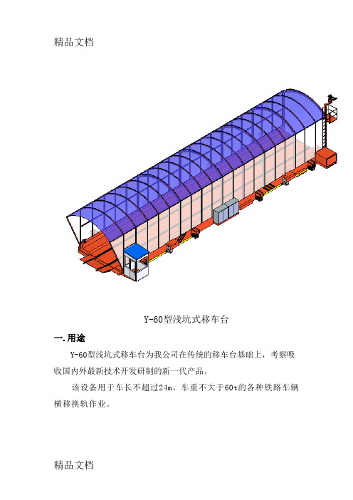
Y-60型浅坑式移车台一.用途Y-60型浅坑式移车台为我公司在传统的移车台基础上,考察吸收国内外最新技术开发研制的新一代产品。
该设备用于车长不超过24m、车重不大于60t的各种铁路车辆横移换轨作业。
二.设备组成及结构特点Y-60型浅坑式移车台主要由车体、渡桥、雨棚、牵车机构、司机室、驱动及从动车轮组、传动装置、安全滑触线供电装置、电气控制等部分组成。
1.车体车体是迁车台的受力载体,整个运载车辆的重量全部由车体承担,因此要求车体具有足够的强度及刚度。
车体主梁采用整体箱形梁焊接结构,横梁采用变截面箱形梁,结构合理;梁钢结构材料均在焊前进行预处理。
车体上铺设有供车辆通过的轨道,轨距为1435mm。
轨道两侧均设有走台,宽度600mm;在车体横梁上部铺有面板,面板下部为型钢框架结构,顶部铺有花纹钢板,便于其他车辆和行人通过,可满足10t以下的轮胎车辆通过,保证无塑性变形;由于采用合理的结构设计,各构件的受力分配合理,使组成车架的各梁处于等强度受力状态。
2.渡桥该机构是车辆上下移车台的过渡机构。
上部布置与通过轨道结构相同的动轨,下部为斜坡结构。
渡桥在对60T车辆通过有足够的刚度和抗变形能力,并可满足10t以下的轮胎车辆通过;渡桥采用电动推杆推动,结构紧凑,使用可靠。
当牵车时,电动推杆伸出,放下渡桥,使渡桥落至地面,作为牵车引轨;当车辆通过后,电动推杆收回,渡桥离开地面,移车台运行。
渡桥配置与地面等高的固定走台板,便于行人及车辆自由通过,并且外形美观,桥式对接轨道与车体铰接。
3.运行机构该机构由4组主动车轮装置、4组从动车轮装置及2套驱动装置构成。
为保证主动轮的同步运行,四个主动轮分别由两台减速机驱动,每台减速机通过万向联轴器同时驱动两个主动轮,每台减速机由一台变频器控制,通过PLC自动调整变频器的频率来保证各主动轮的同步运行。
主、从动轮装置均由车轮、角型轴承箱、轴承、轴、轴承盖等组成。
车轮轴采用合金钢制造,车轮采用合金铸钢,强度高,耐磨性好,使用寿命长。
高空作业平台使用说明书介绍.docx

⾼空作业平台使⽤说明书介绍.docx注意事项感谢您使⽤本产品,为了您更好地使⽤本产品,请在使⽤前阅读(注意事项)及(使⽤说明书)。
作业车未放置于⽔平、坚固的地⾯上不得起升作业。
严禁在不稳固的地⾯上,尤其是地⾯有空洞及凹凸不稳定的地⾯作业。
对作业平台进⾏检修时,必须停机检修。
严禁把作业平台作为焊接地线。
⼯作场地风⼒⼤于 6 级或以上时严禁起升作业。
严禁雷⾬天作业。
严禁载物及载⼈起升作业时移动设备,收拢⽀腿。
⽀腿未打开和调⽔平前不得起升作业。
严禁坐、站或爬越⼯作⽃边缘作业。
严禁超载作业。
严禁在⼯作⽃外悬挂各种物品。
严禁对设备做任何影响稳定性的修改。
严禁作业时⼯作臂下及⽃下部有⼈、物障碍,以免发⽣危险。
⽬录⼀、概述 (2)⼆、主要技术性能 (2)三、主要机构 (3)四、使⽤须知 (3)五、维护保养 (6)六、液压系统常见故障分析处理: (8)七、备⽤清单 (9)⼋、随机⽂件 (9)九、附图: (9)GTBZ-11D型⾼空作业平台使⽤说明书⼀、概述GTBZ-11D 型⾼空作业平台是安装在特制的⾃⾏式底盘上的全液压折叠⼯作臂式⾼空作业平台,⼯作臂360o 全回转机构和液压蛙式⽀腿,本平台结构紧凑、操作⽅便、安全可靠、外型美观,其⼴泛适⽤于市政建设、园林、交通、供电、邮电、⼯矿企业等需进⾏⾼空作业的场所。
⼆、主要技术性能项⽬最⼤作业⾼度平台距地⾼度最⼤作业幅度平台额定承载驱动型式电源电压电池充电时间灯光配置电池规格电池数量电池连接形式油泵电机功率电机功率臂架升降速度臂架回旋⾓度⼯作⽃旋转⾓度制动形式液压系统⼯作压⼒外型尺⼨m2 整体重量抗风能⼒⽀撑型式GTBZ-11D型⾼空作业平台参数表单位参数备注m11mmKg200蓄电池V48V6-9 ⼩时配AH/V150/124串联KW3KWm/s~36001800液压MPa12mm4800×1950×3000Kg2100级≦ 6蛙式液压⽀撑三、主要机构1、动⼒源GTBZ-11D型⾼空作业平台采⽤蓄电池为动⼒,驱动后桥和液压泵⼯作。
汽车抬升器说明书.pdf_1718750929.0642705

the frame for lifting. use vehicle manufacturers instructions on proper lifting. 9. No alterations to the jack shall be made 10. Only attachments, restraints, or adapters supplied by the manufacturer shall be used. 11. Failure to heed these warnings may result in personal injury and/or property damage.
2. Do not overload this jack beyond the rated capacity. 3. This jack is designed for use only on hard level
surfaces capable of sustaining the load. 4. This is a lifting device only, immediately after lifting,
1.8 tonnes métriques 1.8 tonnes métriques 3.6 tonnes métriques 3.6 tonnes métriques 5.4 tonnes métriques 5.4 tonnes métriques
MODELE MODELE MODELE MODELE MODELE MODELE MODELE MODELE MODELE