62133电池内部短路
电瓶内部短路修复方法
电瓶内部短路修复方法
电瓶内部短路通常是由于电瓶内部的正负极之间的隔离膜损坏或污染导致的,修复方法如下:
1. 首先,断开电瓶与电源之间的连接,确保电瓶与电源完全分离。
2. 将电瓶取下并放置在安全的地方,然后检查电瓶的外部是否有明显的损坏。
3. 使用电瓶温度计检查电瓶的温度,确保电瓶没有过热或其它异常情况。
4. 将电瓶分解成各个组件,包括正负极和隔离膜。
5. 检查隔离膜的状况,如果发现有损坏或污染,可以尝试修复或更换隔离膜。
6. 使用绝缘胶带或其它隔离材料将正负极之间隔离,确保它们不会直接接触。
7. 重新组装电瓶并将其连接到电源,确认连接正确无误。
8. 使用测试仪器检查电瓶的工作状态,包括电压和电流等参数,确保短路问题已修复。
请注意,修复电瓶内部短路需要具备一定的电子知识和技巧,
如果您不确定操作步骤或担心安全问题,建议寻求专业人士的帮助。
此外,请确保在正确的工作环境下进行修复,并遵循相关的安全操作规范。
锂电池安全标准 IEC62133

IEC62133 ed.2目录绝缘和布线测试 (2)振动测试 (3)高温环境模型外壳压力测试 (4)温度循环测试 (5)外部短路测试: (20︒C ±5ºC) (6)外部短路测试: (55°C ± 5︒C) (7)自由跌落 (8)机械冲击(冲击危害) (9)热滥用测试 (10)电芯挤压测试 (11)低压测试: (12)强制放电测试: (13)恒压持续充电 (电芯) (14)外部短路 (电芯) (15)外部短路 (电池) (16)电池的过充测试 (17)电芯的强制内部短路测试 (18)绝缘和布线测试测试方法有金属裸露表面且金属面不带电的电池,在绝缘阻抗测试仪输出500Vdc电压情况下,测量电池金属表面与正极端子间的绝缘阻抗,测量需持续一定时间,绝缘电阻测试电压典型作用时间为60秒。
测试结果要求金属外壳电池和正极端子间绝缘电阻不大于等于5 M 。
振动测试测试方法样品做简单的谐振运动,振幅为0.76mm,最大位移1.52mm。
频率以1Hz/min的速度在10Hz和55Hz之间变化。
在每个震动方向上频率从10Hz到55Hz,然后从55Hz返回10Hz,往返时间在90 5分钟内。
测试完成1小时后检查电芯。
测试结果要求样品没有泄露、起火、爆炸的迹象。
高温环境模型外壳压力测试测试方法完全充满电电池放在空气对流的烤炉中,烤炉温度为70︒C ± 2︒C。
电池在烤炉中保持7小时,之后小心移出,恢复到室温(20︒C ± 5︒C)后检查。
测试结果要求样品外壳没有变形或使内部组件暴露的物理弯曲。
温度循环测试测试方法完全充电电芯/电池按照下面过程在强制通风间内进行温度循环测试:步骤1:将样品放在室温为75︒C ±2︒C的室内,保持4小时。
步骤2:在30分钟内将室温降低到20︒C ± 5︒C,保持2小时。
步骤3:30分钟内将室温降低到–20︒C ± 2︒C,保持4小时。
IEC62133-2012 中文翻译版

含碱性或其它非酸性电解质的二次电芯和电池(组)便携式密封二次单体电芯,由电芯组成的电池(组)以及应用于便携式设备的安全要求1、范围本国际标准规定了含碱性或其它非酸性电解质的便携式密封二次电芯和电池(组)(不包括纽扣型电池),在预期使用和可预见性滥用情况下的安全性能要求和测试方法2、引用标准本标准内容引用了下列文件或其中的条款,且在运用中是不可或缺的。
对标明日期的参考文献,使用指定的版本。
对未标明日期的参考文献,采用其最新版本(涵盖任何修订)。
IEC60050-482,国际电工术语——第482章:原单体电池和电池(组)以及二次单体电池和电池(组)IEC61951-1,含碱性或其它非酸性电解质的二次电芯和电池(组)——便携式密封可充电式单体电芯——第1部分:镍镉电池IEC61951-2,含碱性或其它非酸性电解质的二次电芯和电池(组)——便携式密封可充电式单体电芯——第2部分:镍氢电池IEC61960,含碱性或其它非酸性电解液的二次电芯和电池(组)——应用于便携式二次锂电芯和电池(组)ISO/IEC指南51,安全反面--标准中涉及到相关方面的应用指南3、术语定义IEC60050-482和ISO/IEC指南51中包含术语以及下列定义适用于本标准。
3.1 安全免于不可接受的风险3.2 风险伤害和伤害严重性的发生概率集合3.3伤害身体受伤或对人健康的损害或对财产的损失或对环境的破坏3.4 危险性伤害的潜在根源3.5 预定用途和供应商提供的说明书、操作指南信息一致的产品的使用、处理和服务3.6 合理可预计的滥用产品的使用、处理和服务虽不符合供应商提供的使用要求,但他它将产生的结果可根据人的行为估计3.7 二次单体电池通过直接转换化学能提供电能的基本单元,它可以包括电极、隔膜、电解液、壳体和端子,并被设计为可以对其充电3.8 二次电池组二次单体电池的组装体,电压、尺寸、端子排列形式、容量和额定容量为其电性能特征的电能源3.9漏液可见的液体电解质流失3.10 排气为防止破裂或爆炸,设计一种方法来释放电池内部过大的压力3.11 破裂由于内部或外部原因造成单体电池壳体或电池组壳体破裂。
IEC62133电池安全测试要求总括
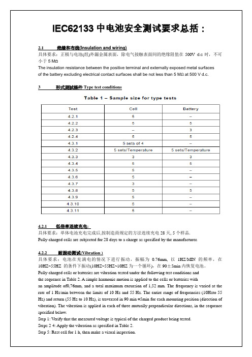
IEC62133中电池安全测试要求总括:2.1绝缘和布线(Insulation and wiring)具体要求:正极与电池(组)外漏金属表面,除电气接触表面间的绝缘阻值在500V d.c时,不可小于5 MΩThe insulation resistance between the positive terminal and externally exposed metal surfacesof the battery excluding electrical contact surfaces shall be not less than 5 MΩ at 500 V d.c.3 形式測試條件Type test conditions4.2.1 低倍率连续充电:具体要求:单体电池充电完成后,按制造商规定的方法连续充电28天, 5个样品.Fully charged cells are subjected for 28 days to a charge as specified by the manufacturer.4.2.2 耐振动测试(Vibration )具体要求:电池在充满电的情况下进行振动,振幅为0.76mm, 以1HZ/MIN 的频率,在10HZ~55HZ 的条件下振动(10HZ~55HZ~10HZ为一个循环),在90±5min内恢复电池。
Fully charged cells or batteries are vibration-tested under the following test conditions andthe sequence in Table 2. A simple harmonic motion is applied to the cells or batteries withan amplitude of0,76mm, and a total maximum excursion of 1,52 mm. The frequency is varied at the rate of 1 Hz/min between the limits of 10 Hz and 55 Hz. The entire range of frequencies (10Hzto 55 Hz) and return (55 Hz to 10 Hz), is traversed in 90 min ±5min for each mounting position (direction of vibration). The vibration is applied in each of three mutually perpendicular directions, in the sequence specified below.Step 1: Verify that the measured voltage is typical of the charged product being tested.Steps 2-4: Apply the vibration as specified in Table 2.Step 5: Rest cell for 1 h, then make a visual inspection.IEC 61960-2011 marking.pdf IEC 61951-2 2003 marking.pdf。
锂离子电池的安全性及相关标准规定
锂离子电池的安全性及相关标准规定锂离子电池安全性及相关标准规定锂离子电池是一种高能量密度、长寿命、无记忆效应、环保等优点的电池,被广泛应用于便携式设备、电动工具、电动汽车等领域,但其安全性问题也备受关注。
本文将介绍锂离子电池的安全性及相关标准规定。
一、锂离子电池的安全性问题1. 热失控当锂离子电池内部温度达到一定程度时,电池的正副电极、电解液等将会燃烧甚至爆炸,造成严重事故。
热失控的主要原因是电池内部产生热量无法及时散发出去,导致电池内部温度升高。
2. 机械失控锂离子电池内部物质的结构很脆弱,在受到机械碰撞、摩擦等外力作用时,可能会发生机械失控。
3. 内短路内短路是锂离子电池内部发生短路的一种情况。
由于正负电极之间隔膜被损坏,电解液中的离子可以直接通过短路通道流动,导致电池损坏或甚至爆炸。
4. 外短路外短路发生在电池的正负接口被短路时,电池可以在极短的时间内输出大量电流,可能会引发电池爆炸。
二、锂离子电池相关标准规定1. UL标准UL标准是美国安全试验实验室(Underwriters Laboratories)制定的电池安全标准,主要用于规范锂离子电池的安全性能。
2. IEC标准国际电工委员会(IEC)制定了IEC 62133标准,用于规范电池的安全性能,其中包括锂离子电池。
3. GB/T标准GB/T是中国标准制定机构国家标准化管理委员会发布的标准。
《锂离子电池安全性要求和测试方法》(GB/T 31241-2014)是规范锂离子电池安全性能的重要标准。
4. UN标准联合国(UN)也制定了一系列标准来规范锂离子电池的安全性能,主要针对电池的包装和运输。
综上所述,锂离子电池的安全性问题备受关注,相关标准规定的制定和实施对于确保锂离子电池的安全性具有关键性作用。
同时,生产、使用锂离子电池时也要严格按照标准规定进行操作,尽可能避免电池对人身和环境造成损害。
未来发展趋势和前景随着科技的不断发展和新能源的广泛应用,锂离子电池的前景越来越广阔。
IEC62133讲解
1.概述1.1范围本国际标准规定了便携式密封式二次电池包括碱性的或非酸性电解液电池芯和电池(不包含扣式电池)在正常使用和可能的误操作下的安全性要求和试验方法。
1.2引用标准下列标准化文件所包含的条文,通过在本国际标准的引用而构成本标准的条文,有时效规定的引用,引用标准在本标准颁布后的改编、修正版不在引用之列。
当然本国际标准制定委员会鼓励去探讨引用下列所示标准最新版本的可能性。
无时效的引用,最新版本的内容将被采用。
IEC和ISO委员将继续登记最新的有效的国际标准。
IEC 60285 碱性二次电池芯和电池——密封式镍镉圆柱型可充单个电池芯IEC 60664(全部章节)有低压系统的设备的绝缘配置IEC 61436二次电池芯和电池包括碱性或非酸性电解液电池——密封式镍氢可充单个电池芯IEC 61440二次电池包括碱性或非酸性电解液电池——密封式镍镉小棱形可充单个电池芯IEC 61809 二次电池包括碱性或非酸性电解液电池——便携式密封式碱性二次电池芯和电池安全要求IEC 61951-1二次电池包括碱性或非酸性电解液电池——便携式密封可充电电池芯第一部分:镍—镉电池IEC 61951-2二次电池包括碱性或非酸性电解液电池——便携式密封可充电电池芯第一部分:镍氢电池IEC 61960-1 and 61960-2便携式二次锂电池芯和电池1.二次锂电池芯2.二次锂电池1.3定义本国际标准采用的IEC60050-486和IEC/ISO导则5.1的术语和下列概念。
1.3.1安全性不会发生不可接受的危险1.3.2危险包括发生伤害的可能性和伤害的严重性1.3.3伤害包括人身伤害,对人类健康的危害,对财产的损害及对环境的破坏1.3.4隐患发生伤害的潜在的源由1.3.5正常使用产品的使用过程和服务完全按供应商所提供的规格和使用说明书和文件执行1.3.6可能发生的误操作产品使用不当,没按供应商的要求做,但可能是人类习惯行为导致的结果1.3.7二次电池芯厂家生产出来的电能和化学能转化的基本单元,包含电极、隔膜、电解液、电池壳、接线终端1.3.8二次电池二次电池芯的装配体:有它自己的电压、尺寸、终端设计、容量和额定功能1.3.9漏液目测可见的电解液液体的渗出1.3.10 泄放电池芯或电池内部过剩压力在设计的安全阀处释放造成的破裂或爆炸1.3.11破裂由于内部或外面的原因,电池芯的壳或电池壳发生机械破坏,导致爆炸或漏液1.3.12爆炸电池壳炸裂,主要元件猛然冲出来的现象1.3.13起火电池芯或电池喷射出火焰1.3.14便携式电池安装在手提式用具上的电池1.3.15便携式电池芯可以装配到便携式电池上的电池芯1.3.16额定容量生产厂标明的C5Ah (安时)容量,是指电池在规定条件下,充电、储存、放电后,在20℃以0.2I t A的参考试验电流放电到终止电压1.0V所释放的放电容量1.4 参数测量公差对于所有的规定的参数或实际参数的精度控制和测量值,都应满足下列公差:a)±1%——电压b)±1%——电流c)±2℃——温度d)±0.1%——时间e)±1%——尺寸f)±1%——容量这些公差包含系统误差和人为误差。
锂电池CB认证标准IEC62133 详细说解析

锂电池CB认证标准IEC62133详细解析自2010年10月26日起,电池类产品如欲取得CB认证证书,除按照UL1642测试外,还须进行额外测试,以确保它们符合电池安全标准IEC 62133的要求。
在特定的过渡期结束后,即从2011年6月27日起,IEC62133标准将全面取代UL1642,电池类产品取得CB证书只须符合IEC62133的要求。
众所周知,电池使用不当,会导致如烧伤和火灾等事故。
近年来电池安全事故频传,美国、日本、俄罗斯等国均强制要求电池按照专门标准进行检测。
我国作为电池出口大国,占据全球一半以上的生产产量。
近年来,宁波地区电池产业发展势头迅猛,上百家制造企业中涌现出口不少知名品牌,已成为浙江省初具规模的电池生产基地,今年1-10月,已有2.35亿美元电池出口顺利出口至美国、欧盟、日本东南亚、台湾等各个国家和地区。
电池产业正处于结构升级的关键阶段,积极拓展出口市场意义重大。
检验检疫专家指出,获取电池CB认证证书的电池产品在申请进口国所要求的其它认证证书时,可免除或减少再送样测试,大大缩短产品进入市场的周期,减少成本费用,加速产品出口。
而IEC 62133标准主要包含电芯和电池项目的测试,由于电池的制造和成品检测的复杂性,电池制造企业在检测验证前应对该标准细节有详细了解并在生产中加以控制,如在电芯设计考虑耐持续充电能力,以免在最终检测中因为不符合IEC 62133标准要求而阻碍出口。
振动测试(Vibration )具体要求:电池在充满电的情况下进行振动,振幅为0.76mm, 以1HZ/MIN 的频率,在10HZ~55HZ 的条件下振动(10HZ~55HZ~10HZ为一个循环),在90±5min内恢复电池。
高温冲击测试(Moulded case stress at high ambient temperature)具体要求:电池在70℃±2℃条件下,放置7H 以上,然后放置于室温条件下。
电池内短路原因
电池内短路原因电池内短路原因电池内短路是指电池内部的正负极之间或者同极之间发生了直接的、不应有的接触,导致电流绕过了预定的路径,从而引起电池失效、热失控、爆炸等严重后果。
电池内短路是目前各种类型电池中最常见的故障之一,因此深入了解其原因对于提高电池安全性非常必要。
一、外部因素1.1 机械损伤机械损伤是指外力对电池造成物理上的损伤,如挤压、撞击等。
当外力作用于电池时,正负极之间或同极之间可能会发生接触,导致短路。
1.2 液体渗漏液体渗漏是指在使用过程中,由于某些原因导致电解质泄漏到正负极之间或同极之间,使得两个极端发生直接接触而产生短路。
液体渗漏可能由于材料缺陷、设计不合理或者使用条件恶劣等多种原因引起。
1.3 高温环境高温环境会导致电池内部的化学反应加速,同时也会使得电池内部的材料膨胀,从而增加了正负极之间或同极之间的接触面积,引起短路。
二、内部因素2.1 金属颗粒在制造过程中,电池内部可能残留有金属颗粒等杂质。
这些杂质可能在电池使用过程中移动到正负极之间或同极之间,导致短路。
2.2 极片穿孔在制造过程中,由于生产工艺不当或者设备故障等原因,可能会导致极片穿孔。
这种情况下,电解液可能会泄漏到正负极之间或同极之间,导致短路。
2.3 分解反应分解反应是指由于正常使用情况下的化学反应失控而引起的短路。
例如,在充电时,如果电池内部产生气泡而堵塞了通道,则气泡周围的液体就无法再次参与化学反应。
这样一来,在充电过程中就会形成局部过压区域,并且容易引发分解反应。
三、总结电池内短路是一种非常危险的故障,需要我们在使用电池时格外注意。
了解电池内短路的原因,可以帮助我们更好地预防和处理这种故障。
在使用电池时,应该避免机械损伤、避免高温环境、避免液体渗漏等情况,并且要选择质量可靠的电池产品。
如果发现电池出现异常情况,应该立即停止使用,并且妥善处理。
- 1、下载文档前请自行甄别文档内容的完整性,平台不提供额外的编辑、内容补充、找答案等附加服务。
- 2、"仅部分预览"的文档,不可在线预览部分如存在完整性等问题,可反馈申请退款(可完整预览的文档不适用该条件!)。
- 3、如文档侵犯您的权益,请联系客服反馈,我们会尽快为您处理(人工客服工作时间:9:00-18:30)。
a) Test results which verify that the acceptance of lithium into the negative electrode activematerial when the cell is charged at the new low limit is equivalent or higher than that when the cell is charged at the low limit of the current low temperature range. b) Test results which verify that the cells charged at the new low limit of the temperaturerange -5 °C when tested by the methods specified in 8.2 to 8.3 meet the requirements.A.4.5 Scope of the application of charging currentThe charging current, as per specified in the above, is not applied to alternative current of over 50 kHz, which assumes ripple and others, since lithium-ion batteries do not respond to such effects. (Ripple currents over 50 kHz are ok)A.5 Sample preparationA.5.1 GeneralIn order to provide more information regarding the sample preparation for test 8.3.9 the following additional details are provided. A.5.2Insertion procedure for nickel particle to generate internal shortThe insertion procedure is carried out at 20 q C r 5 q C and under -25 q C of DEW points. A.5.3Disassembly of charged cellRemove winding core (assembled electrode/separator, roll, and coil) from the charged cell (See Figure A.5 and Figure A.8). A.5.4Shape of nickel particleThe shape of nickel particle shall be as shown in Figure A.2.Dimensions: Height: 0,2 mm; Thickness: 0,1 mm; L shape (Angle: 90 ± 10°): 1,0 mm for each side with 5 % tolerance. Material: more than 99 %( mass fraction) pure nickel.Dimensions in millimetersFigure A.2 – Shape of nickel particleA.5.5 Insertion of nickel particle to cylindrical cell A.5.5.1Insertion of nickel particle to winding corea) Insertion of nickel particle between positive (active material) coated area and negative(active material) coated area for cylindrical cell. (see Figure A.5)1) If outer turn of positive substrate is aluminum foil, cut off foil at the dividing linebetween aluminum foil and active material for active material to active material short test.1,01,00,10,2IEC 2198/12--````,``,,,`,,``,,``,,````,``,-`-`,,`,,`,`,,`---2) Insert nickel particle between positive active material and separator. The alignment ofnickel particle shall be as shown in Figure A.3. Position of the insertion of nickel particle shall be at 20 mm from edge of the cut aluminum foil. Direction of L-shaped corner is towards the direction of winding.Figure A.3 – Nickel particle insertion position between positive and negativeactive material coated area of cylindrical cellb) Insertion of nickel particle between positive aluminum foil (uncoated area) and negative(active material) coated area for cylindrical cell.When aluminum foil of positive electrode is exposed at outer turn and the aluminum foil is facing the coated negative active material, following procedure shall be used.1) When aluminum foil of positive electrode is exposed at outer turn, cut out thealuminum foil at 10 mm from the dividing line between aluminum foil and active material. 2) Insert Ni particle between aluminum foil and separator. The alignment of nickel particleshall be shown in Figure A.4.Position of the insertion of nickel particle shall be at 1,0 mm from the edge of the coating of positive active material on aluminum foil.Figure A.4 – Nickel particle insertion position between positive aluminum foil andnegative active material coated area of cylindrical cellNegative activeWidthNegative activeSeparatorIEC 2199/12IEC 2200/12Figure A.5 – Disassembly of cylindrical cell20 mmNegative tabPositive tabExtracted winding corePlace the Ni particle in the centerNi particleInsulating sheetThe Ni particle is under the separatorPositive cut endMark the position of the Ni particleAdhesive tapeIEC 2201/12A.5.5.2 Mark the position of nickel particle on the both end of winding core of theseparatorThe procedure is as follows.a) Place insulating sheet between the separator that is facing to nickel particle and thenegative electrode to protect against short-circuits.b) Manually roll back the electrodes and separator keeping the nickel particle in place andapply adhesive tape to the winding core.c) Mark position of the nickel particle across the winding core.d) Put winding core in a polyethylene bag with sealing zipper and seal it. Put thepolyethylene bag into aluminum-laminated bag to prevent from drying out.Remark: Procedure shall be completed within 30 min.A.5.6 Insertion of nickel particle to prismatic cella) Prior to inserting nickel particle, insert an insulating sheet between the negative electrodeand the separator that is below nickel particle and the negative electrode, as shown in Figure A.6, to protect against short-circuit.b) Insertion of nickel particle to winding core1) Insertion of nickel particle between positive (active material) coated area and negative(active material) coated area for prismatic cell. (see Figure A.8)i) Insert nickel particle between positive (active material) coated area and separatoror between separator and negative (active material) coated area. In case ofaluminum cell enclosure, insert nickel particle between positive (active material)coated area and separator.ii) Insert nickel particle between positive active material and separator. The alignment of nickel particle shall be shown in Figure A.6.Nickel particle is set at the center(diagonally) of the winding core. Direction of nickel particle L-shape corner istowards the direction of winding.Figure A.6 – Nickel particle insertion position between positive and negative(active material) coated area of prismatic cell2) Insertion of nickel particle between positive aluminum foil (uncoated area) andnegative (active material) coated area for prismatic cell. When aluminum foil of positiveelectrode is exposed at outer turn and the aluminum foil is faced to coated negative active material, the following test shall be performed:i) The aluminum foil of positive electrode is exposed at outer turn and the aluminumfoil is faced to coated negative active material, insert nickel particle between aluminum foil and separator; ii) The alignment of nickel particle shall be shown in Figure A.7. Nickel particle is setat the centre of flat winding core surface. Direction of nickel particle L - shape corner is towards the direction of winding.Figure A.7 – Nickel particle insertion position between positive aluminum foil andnegative (active material) coated area of prismatic celliii) Manually roll back the electrodes and separator keeping the nickel particle in placeand adhesive tape the winding core. iv) Mark the position of nickel particle across the winding core.v) Put two layers of polyimide tape (10 mm width, 25 μm thickness) at the markingposition. vi) Put winding core into a polyethylene bag with sealing zipper and seal it. Put thepolyethylene bag into aluminum-laminated bag to prevent from drying.Remark: Procedure should be completed within 30 min.Ni particleIEC 2203/12--````,``,,,`,,``,,``,,````,``,-`-`,,`,,`,`,,`---Positive tab Negative tabRemoving winding coreRemove outer layers and put insulating sheet on negative surfaceInsulating sheetAfter roll back the separator, put nickel particleat the centre of the winding core.Put nickel particle on separatorRoll back the electrode and separator and put two layers of polyimide tapeat the position of the nickel particle.IEC 2204/12 Figure A.8 – Disassembly of prismatic cells。