叠层CSP封装工艺仿真中的有限元应力分析_英文_
最新封装体叠层(PoP,Package-on-Package)技术

封装体叠层(PoP,Package-on-Package)技术在逻辑电路和存储器集成领域,封装体叠层(PoP)已经成为业界的首选,主要用于制造高端便携式设备和智能手机使用的先进移动通讯平台。
移动便携市场在经历2009年的衰退之后,已经显示反弹迹象,进入平稳增长阶段,相比而言,智能手机的增长比其它手机市场更快,占据的市场份额正不断增加。
与此同时,PoP技术也在移动互联网设备、便携式媒体播放器等领域找到了应用。
这些应用带来了对PoP技术的巨大需求,而PoP也支持了便携式设备对复杂性和功能性的需求,成为该领域的发动机。
像应用处理器或基带/应用存储器组合这样的核心部件,其主要的生产企业都已经或计划使用PoP解决方案(图1)。
图1. 尽管业界逐渐转向使用倒装芯片技术,但引线键合依然具有成本优势,并在PoP技术中得以继续使用。
PoP技术演化对于底层PoP封装来说,引线键合正迅速被倒转焊技术所取代。
对更小封装尺寸的要求,推动着焊球节距的不断缩小,目前在底层PoP中,0.4 mm的焊球节距已经非常普遍。
与此同时,顶层封装的DRAM芯片,以及包含闪存的DRAM芯片,都有更高速度和带宽的要求,这对应着顶层封装需要具有数目更多的焊球。
由于同时要求更大焊球数目和更小封装尺寸,因而降低顶层封装的焊球节距非常必要。
在过去0.65 mm的节距就足够了,而现在需要使用0.5 mm的节距,而0.4 mm的节距也即将上马被采用。
封装间焊球节距的缩小带来很多问题。
首先,更小的焊球节距要求更小的焊球尺寸,而且顶层封装与底层封装的间隙高度在回流之后也会更小。
当然,这影响底层封装之上允许的器件最大高度。
目前,在这一方面所作的努力大部分都是向倒装芯片和更密封装间互连转变,以满足对更小封装尺寸和叠层高度的要求(图2)。
图2. 随着PoP技术的演变,封装体的尺寸、高度和焊球节距的发展趋势。
退一步来说,尽管包含逻辑处理器的底层封装体正明显地从引线键合向倒装芯片技术转变,但引线键合技术并未就此退出历史舞台,依然还是顶层存储器件封装的标准互连方法。
FOW在叠层CSP封装中的应用
FOW在叠层CSP封装中的应用
张天刚;毛凌锋
【期刊名称】《电子与封装》
【年(卷),期】2009(9)11
【摘要】随着电子封装微型化、多功能化的发展,三维封装已成为封装技术的主要发展方向,叠层CSP封装具有封装密度高、互连性能好等特性,是实现三维封装的重要技术.针对超薄芯片传统叠层CSP封装过程中容易产生圆片翘曲、金线键合过程中容易出现OBOP不良、以及线弧(wire loop)的CPK值达不到工艺要求等问题,文中简要介绍了芯片减薄方法对圆片翘曲的影响,利用有限元(FEA)的方法进行芯片减薄后对悬空功能芯片金线键合(Wirebond)的影响进行分析,Film on Wire(FOW)的贴片(Die Attach)方法在解决悬空功能芯片金线键合中的应用,以及FOW贴片方式对叠层CSP封装流程的简化.采用FOW贴片技术可以达到30%的成本节约,具有很好的经济效益.
【总页数】5页(P1-4,11)
【作者】张天刚;毛凌锋
【作者单位】飞索半导体中国有限公司,江苏,苏州,215021;苏州大学电子信息学院微电子系,江苏,苏州,215021;苏州大学电子信息学院微电子系,江苏,苏州,215021【正文语种】中文
【中图分类】TN305.94
【相关文献】
1.CSP封装与安装技术在手机中的应用 [J], 苇菁
2.叠层芯片引线键合技术在陶瓷封装中的应用 [J], 廖小平;高亮
3.晶圆叠层3D封装中晶圆键合技术的应用 [J], 田芳
4.叠层CSP封装工艺仿真中的有限元应力分析 [J], 刘彪;王明湘;林天辉
5.多目标优化方法在叠层QFN封装结构优化中的应用 [J], 周喜;冷雪松;李莉;马亚辉
因版权原因,仅展示原文概要,查看原文内容请购买。
有限元分析中英文对照资料
The finite element analysisFinite element method, the solving area is regarded as made up of many small in the node connected unit (a domain), the model gives the fundamental equation of sharding (sub-domain) approximation solution, due to the unit (a domain) can be divided into various shapes and sizes of different size, so it can well adapt to the complex geometry, complex material properties and complicated boundary conditionsFinite element model: is it real system idealized mathematical abstractions. Is composed of some simple shapes of unit, unit connection through the node, and under a certain load.Finite element analysis: is the use of mathematical approximation method for real physical systems (geometry and loading conditions were simulated. And by using simple and interacting elements, namely unit, can use a limited number of unknown variables to approaching infinite unknown quantity of the real system.Linear elastic finite element method is a ideal elastic body as the research object, considering the deformation based on small deformation assumption of. In this kind of problem, the stress and strain of the material is linear relationship, meet the generalized hooke's law; Stress and strain is linear, linear elastic problem boils down to solving linear equations, so only need less computation time. If the efficient method of solving algebraic equations can also help reduce the duration of finite element analysis.Linear elastic finite element generally includes linear elastic statics analysis and linear elastic dynamics analysis from two aspects. The difference between the nonlinear problem and linear elastic problems:1) nonlinear equation is nonlinear, and iteratively solving of general;2) the nonlinear problem can't use superposition principle;3) nonlinear problem is not there is always solution, sometimes even no solution. Finite element to solve the nonlinear problem can be divided into the following three categories:1) material nonlinear problems of stress and strain is nonlinear, but the stress and strain is very small, a linear relationship between strain and displacement at this time, this kind of problem belongs to the material nonlinear problems. Due to theoretically also cannot provide the constitutive relation can be accepted, so, general nonlinear relations between stress and strain of the material based on the test data, sometimes, to simulate the nonlinear material properties available mathematical model though these models always have their limitations. More important material nonlinear problems in engineering practice are: nonlinear elastic (including piecewise linear elastic, elastic-plastic and viscoplastic, creep, etc.2) geometric nonlinear geometric nonlinear problems are caused due to the nonlinear relationship between displacement. When the object the displacement is larger, the strain and displacement relationship is nonlinear relationship. Research on this kind of problemIs assumes that the material of stress and strain is linear relationship. It consistsof a large displacement problem of large strain and large displacement little strain. Such as the structure of the elastic buckling problem belongs to the large displacement little strain, rubber parts forming process for large strain.3) nonlinear boundary problem in the processing, problems such as sealing, the impact of the role of contact and friction can not be ignored, belongs to the highly nonlinear contact boundary. At ordinary times some contact problems, such as gear, stamping forming, rolling, rubber shock absorber, interference fit assembly, etc., when a structure and another structure or external boundary contact usually want to consider nonlinear boundary conditions. The actual nonlinear may appear at the same time these two or three kinds of nonlinear problems.Finite element theoretical basisFinite element method is based on variational principle and the weighted residual method, and the basic solving thought is the computational domain is divided into a finite number of non-overlapping unit, within each cell, select some appropriate nodes as solving the interpolation function, the differential equation of the variables in the rewritten by the variable or its derivative selected interpolation node value and the function of linear expression, with the aid of variational principle or weighted residual method, the discrete solution of differential equation. Using different forms of weight function and interpolation function, constitute different finite element methods. 1. The weighted residual method and the weighted residual method of weighted residual method of weighted residual method: refers to the weighted function is zero using make allowance for approximate solution of the differential equation method is called the weighted residual method. Is a kind of directly from the solution of differential equation and boundary conditions, to seek the approximate solution of boundary value problems of mathematical methods. Weighted residual method is to solve the differential equation of the approximate solution of a kind of effective method.Hybrid method for the trial function selected is the most convenient, but under the condition of the same precision, the workload is the largest. For internal method and the boundary method basis function must be made in advance to meet certain conditions, the analysis of complex structures tend to have certain difficulty, but the trial function is established, the workload is small. No matter what method is used, when set up trial function should be paid attention to are the following: (1) trial function should be composed of a subset of the complete function set. Have been using the trial function has the power series and trigonometric series, spline functions, beisaier, chebyshev, Legendre polynomial, and so on.(2) the trial function should have until than to eliminate surplus weighted integral expression of the highest derivative low first order derivative continuity. (3) the trial function should be special solution with analytical solution of the problem or problems associated with it. If computing problems with symmetry, should make full use of it. Obviously, any independent complete set of functions can be used as weight function. According to the weight function of the different optionsfor different weighted allowance calculation method, mainly include: collocation method, subdomain method, least square method, moment method and galerkin method. The galerkin method has the highest accuracy.Principle of virtual work: balance equations and geometric equations of the equivalent integral form of "weak" virtual work principles include principle of virtual displacement and virtual stress principle, is the floorboard of the principle of virtual displacement and virtual stress theory. They can be considered with some control equation of equivalent integral "weak" form. Principle of virtual work: get form any balanced force system in any state of deformation coordinate condition on the virtual work is equal to zero, namely the system of virtual work force and internal force of the sum of virtual work is equal to zero. The virtual displacement principle is the equilibrium equation and force boundary conditions of the equivalent integral form of "weak"; Virtual stress principle is geometric equation and displacement boundary condition of the equivalent integral form of "weak". Mechanical meaning of the virtual displacement principle: if the force system is balanced, they on the virtual displacement and virtual strain by the sum of the work is zero. On the other hand, if the force system in the virtual displacement (strain) and virtual and is equal to zero for the work, they must balance equation. Virtual displacement principle formulated the system of force balance, therefore, necessary and sufficient conditions. In general, the virtual displacement principle can not only suitable for linear elastic problems, and can be used in the nonlinear elastic and elastic-plastic nonlinear problem.Virtual mechanical meaning of stress principle: if the displacement is coordinated, the virtual stress and virtual boundary constraint counterforce in which they are the sum of the work is zero. On the other hand, if the virtual force system in which they are and is zero for the work, they must be meet the coordination. Virtual stress in principle, therefore, necessary and sufficient condition for the expression of displacement coordination. Virtual stress principle can be applied to different linear elastic and nonlinear elastic mechanics problem. But it must be pointed out that both principle of virtual displacement and virtual stress principle, rely on their geometric equation and equilibrium equation is based on the theory of small deformation, they cannot be directly applied to mechanical problems based on large deformation theory. 3,,,,, the minimum total potential energy method of minimum total potential energy method, the minimum strain energy method of minimum total potential energy method, the potential energy function in the object on the external load will cause deformation, the deformation force during the work done in the form of elastic energy stored in the object, is the strain energy.The convergence of the finite element method, the convergence of the finite element method refers to when the grid gradually encryption, the finite element solution sequence converges to the exact solution; Or when the cell size is fixed, the more freedom degree each unit, the finite element solutions tend to be more precise solution. Convergence condition of the convergence condition of the finite element finite element convergence condition of the convergence condition of the finite element finite element includes the following four aspects: 1) within the unit, thedisplacement function must be continuous. Polynomial is single-valued continuous function, so choose polynomial as displacement function, to ensure continuity within the unit. 2) within the unit, the displacement function must include often strain. Total can be broken down into each unit of the state of strain does not depend on different locations within the cell strain and strain is decided by the point location of variables. When the size of the units is enough hours, unit of each point in the strain tend to be equal, unit deformation is uniform, so often strain becomes the main part of the strain. To reflect the state of strain unit, the unit must include the displacement functions often strain. 3) within the unit, the displacement function must include the rigid body displacement. Under normal circumstances, the cell for a bit of deformation displacement and displacement of rigid body displacement including two parts. Deformation displacement is associated with the changes in the object shape and volume, thus producing strain; The rigid body displacement changing the object position, don't change the shape and volume of the object, namely the rigid body displacement is not deformation displacement. Spatial displacement of an object includes three translational and three rotational displacement, a total of six rigid body displacements. Due to a unit involved in the other unit, other units do rigid body displacement deformation occurs will drive unit, thus, to simulate real displacement of a unit, assume that the element displacement function must include the rigid body displacement. 4) the displacement function must be coordinated in public boundary of the adjacent cell. For general unit of coordination is refers to the adjacent cell in public node have the same displacement, but also have the same displacement along the edge of the unit, that is to say, to ensure that the unit does not occur from cracking and invade the overlap each other. To do this requires the function on the common boundary can be determined by the public node function value only. For general unit and coordination to ensure the continuity of the displacement of adjacent cell boundaries. However, between the plate and shell of the adjacent cell, also requires a displacement of the first derivative continuous, only in this way, to guarantee the strain energy of the structure is bounded. On the whole, coordination refers to the public on the border between neighboring units satisfy the continuity conditions. The first three, also called completeness conditions, meet the conditions of complete unit is complete unit; Article 4 is coordination requirements, meet the coordination unit coordination unit; Otherwise known as the coordinating units. Completeness requirement is necessary for convergence, all four meet, constitutes a necessary and sufficient condition for convergence. In practical application, to make the selected displacement functions all meet the requirements of completeness and harmony, it is difficult in some cases can relax the requirement for coordination. It should be pointed out that, sometimes the coordination unit than its corresponding coordination unit, its reason lies in the nature of the approximate solution. Assumed displacement function is equivalent to put the unit under constraint conditions, the unit deformation subject to the constraints, this just some alternative structure compared to the real structure. But the approximate structure due to allow cell separation, overlap, become soft, the stiffness of the unit or formed (suchas round degree between continuous plate unit in the unit, and corner is discontinuous, just to pin point) for the coordination unit, the error of these two effects have the possibility of cancellation, so sometimes use the coordination unit will get very good results. In engineering practice, the coordination of yuan must pass to use "small pieces after test". Average units or nodes average processing method of stress stress average units or nodes average processing method of stress average units or nodes average processing method of stress of the unit average or node average treatment method is the simplest method is to take stress results adjacent cell or surrounding nodes, the average value of stress.1. Take an average of 2 adjacent unit stress. Take around nodes, the average value of stressThe basic steps of finite element method to solve the problemThe structural discretization structure discretization structure discretization structure discretization to discretization of the whole structure, will be divided into several units, through the node connected to each other between the units; 2. The stiffness matrix of each unit and each element stiffness matrix and the element stiffness matrix and the stiffness matrix of each unit (3) integrated global stiffness matrix integrated total stiffness matrix integrated overall stiffness matrix integrated total stiffness matrix and write out the general balance equations and write out the general balance equations and write out the general balance equations and write a general equation 4. Introduction of supporting conditions, the displacement of each node 5. Calculate the stress and strain in the unit to get the stress and strain of each cell and the cell of the stress and strain and the stress and strain of each cell.For the finite element method, the basic ideas and steps can be summarized as: (1) to establish integral equation, according to the principle of variational allowance and the weight function or equation principle of orthogonalization, establishment and integral expression of differential equations is equivalent to the initial-boundary value problem, this is the starting point of the finite element method. Unit (2) the area subdivision, according to the solution of the shape of the area and the physical characteristics of practical problems, cut area is divided into a number of mutual connection, overlap of unit. Regional unit is divided into finite element method of the preparation, this part of the workload is bigger, in addition to the cell and node number and determine the relationship between each other, also said the node coordinates, at the same time also need to list the natural boundary and essential boundary node number and the corresponding boundary value.(3) determine the unit basis function, according to the unit and the approximate solution of node number in precision requirement, choose meet certain interpolation condition basis function interpolation function as a unit. Basis function in the finite element method is selected in the unit, due to the geometry of each unit has a rule in the selection of basis function can follow certain rules. (4) the unit will be analysis: to solve the function of each unit with unit basis functions toapproximate the linear combination of expression; Then approximate function generation into the integral equation, and the unit area integral, can be obtained with undetermined coefficient (i.e., cell parameter value) of each node in the algebraic equations, known as the finite element equation. (5) the overall synthesis: after the finite element equation, the area of all elements in the finite element equation according to certain principles of accumulation, the formation of general finite element equations. (6) boundary condition processing: general boundary conditions there are three kinds of form, divided into the essential boundary conditions (dirichlet boundary condition) and natural boundary conditions (Riemann boundary conditions) and mixed boundary conditions (cauchy boundary conditions). Often in the integral expression for natural boundary conditions, can be automatically satisfied. For essential boundary conditions and mixed boundary conditions, should be in a certain method to modify general finite element equations satisfies. Solving finite element equations (7) : based on the general finite element equations of boundary conditions are fixed, are all closed equations of the unknown quantity, and adopt appropriate numerical calculation method, the function value of each node can be obtained.有限元分析有限元法求解区域是由许多小的节点连接单元(域),该模型给出了切分的基本方程(子域名)的近似解,由于单位(域)可以分为不同的形状和大小不同的尺寸,所以它能很好的适应复杂的几何形状、材料特性和边界条件复杂,复杂有限元模型:它是真实系统的理想化的数学抽象。
CSP封装有限元分析
有限元法分析与建模课程设计报告报告题目:CSP封装有限元分析学院:机械电子工程学院指导教师:杜平安学生及学号:何志鹏(2013080203)摘要电子元器件在服役条件下,电路的周期性通断和环境温度的周期性变化导致焊点经受温度循环的过程中,由于封装材料之间的热膨胀失配,在焊点的内部将产生周期性的应力应变,诱发裂纹的萌生与扩展,最终造成焊点的失效。
封装的热-力失效问题在CSP中同样很突出:器件通过焊点直接实现异材间的电气及刚性机械连接,而一个焊点的失效就可能造成器件整体的失效。
因而,CSP的热力可靠性引起人们极大的重视。
因此,本例针对CSP封装形式,针对焊球、PCB板、基板、印制线、粘结剂、芯片、和塑封体七部分组成的结构并简化为平面应变问题,采用ANSYS有限元软件模拟其在温度循环载荷下的力学行为。
关键词:CSP封装,温度循环载荷,应力应变,有限元法Abstract目录第1章引言 (7)1.1 CSP背景 (7)1.2 CSP定义 (7)1.3 CSP分类 (7)1.4 CSP的特点 (8)第2章力学及有限元模型 (9)2.1 力学模型 (9)2.2 VISCO108粘塑性单元类型 (9)2.2.1 单元介绍 (9)2.2.2 单元假设和限制 (10)2.3 有限元模型 (10)2.3.1 计算假设和简化 (10)2.3.2 单元类型的选取 (10)2.3.3材料属性 (10)2.3.4 参数设定 (11)第3章模型建立 (12)3.1 参数定义 (12)3.1.1 几何参数设定 (12)3.1.2 定义单元类型 (13)3.1.3 定义材料属性 (14)3.2 实体建模 (19)3.2.1 建立塑封体模型 (19)3.2.2 建立粘结剂模型 (20)3.2.3 建立芯片模型 (20)3.2.4 建立基板模型 (20)3.2.5 建立焊球模型 (21)3.2.6 建立铜质印线 (22)3.2.7 建立PCB板 (23)第4章网格划分 (25)4.1 网格划分设置 (25)4.1.1 PCB板工作平面切割 (25)4.1.2 塑封体工作平面切割 (25)4.2 赋材料属性 (26)4.2.1 定义焊点材料 (26)4.2.2 定义基板材料 (27)4.2.3 定义铜质印线材料 (27)4.2.4 定义塑封体材料 (27)4.2.5 定义芯片材料 (27)4.2.6 定义PCB板材料 (28)4.2.7 定义粘结剂材料 (28)4.3 网格划分 (29)4.3.1 自由网格划分部分 (29)4.3.2 焊点部分网格划分 (30)4.3.3 PCB板映射网格划分 (30)4.3.4 芯片网格划分 (31)4.3.4 塑封体网格划分 (31)第5章边界条件 (32)第6章加载及求解 (33)6.1 设定求解选项及初始载荷 (33)6.3 循环载荷 (34)第7章结果分析 (36)7.1 通用后处理 (36)7.1.1 总体变形分布云图 (36)7.1.2 等效应力分布云图 (37)7.1.3 总体塑性等效应变分布云图 (38)7.2时间历程后处理 (39)7.2.1 X向应力随时间变化图 (39)7.2.2 X向塑性变形随时间变化图 (41)7.2.3 X向弹性应变随时间变化图 (42)7.2.4 X向总应变随时间变化图 (43)7.2.5 危险点的X向应力-总应变滞后环 (44)第8章结论 (46)参考文献 (47)第1章引言1.1 CSP背景要实现更高密度的封装,几十年来主宰、制约电子封装技术发展的芯片小、封装大这一芯片与封装的矛盾显得尤为突出。
ANSYS基础教程——应力分析

ANSYS基础教程——应力分析关键字:ANSYS应力分析ANSYS教程信息化调查找茬投稿收藏评论好文推荐打印社区分享应力分析是用来描述包括应力和应变在内的结果量分析的通用术语,也就是结构分析,应力分析包括如下几个类型:静态分析瞬态动力分析、模态分析谱分析、谐响应分析显示动力学,本文主要是以线性静态分析为例来描述分析,主要内容有:分析步骤、几何建模、网格划分。
应力分析概述·应力分析是用来描述包括应力和应变在内的结果量分析的通用术语,也就是结构分析。
ANSYS 的应力分析包括如下几个类型:●静态分析●瞬态动力分析●模态分析●谱分析●谐响应分析●显示动力学本文以一个线性静态分析为例来描述分析步骤,只要掌握了这个分析步骤,很快就会作其他分析。
A. 分析步骤每个分析包含三个主要步骤:·前处理–创建或输入几何模型–对几何模型划分网格·求解–施加载荷–求解·后处理–结果评价–检查结果的正确性·注意!ANSYS 的主菜单也是按照前处理、求解、后处理来组织的;·前处理器(在ANSYS中称为PREP7)提供了对程序的主要输入;·前处理的主要功能是生成有限元模型,主要包括节点、单元和材料属性等的定义。
也可以使用前处理器PREP7 施加载荷。
·通常先定义分析对象的几何模型。
·典型方法是用实体模型模拟几何模型。
–以CAD-类型的数学描述定义结构的几何模型。
–可能是实体或表面,这取决于分析对象的模型。
B. 几何模型·典型的实体模型是由体、面、线和关键点组成的。
–体由面围成,用来描述实体物体。
–面由线围成,用来描述物体的表面或者块、壳等。
–线由关键点组成,用来描述物体的边。
–关键点是三维空间的位置,用来描述物体的顶点。
·在实体模型间有一个内在层次关系,关键点是实体的基础,线由点生成,面由线生成,体由面生成。
·这个层次的顺序与模型怎样建立无关。
分层切削加工有限元仿真分析
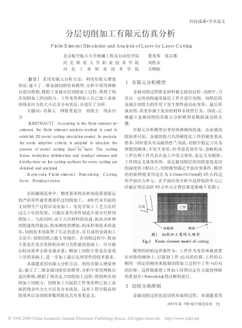
分层切削加工有限元仿真分析FiniteElementSimulationandAnalysisofLayerbyLayerCutting北京航空航天大学机械工程及自动化学院董兆伟张以都刘胜永万晓航[摘要]采用有限元分析方法,利用有限元增量理论,建立了二维金属切削仿真模型,分析中采用网格自适应准则,模拟了金属分层切削加工过程。
得到了每次切削加工的切削力、工件变形和加工后已加工表面的残余应力的大小以及分布状况,并进行了分析。
关键词:有限元网格重划分切削力残余应力[ABSTRACT]Accordingtothefiniteelementin-crement,thefiniteelementanalysismethodisusedtoestablish2Dmetalcuttingsimulationmodel.Inanalysis,themeshadaptivecriteriaisadoptedtosimulatetheprocessofmetalcuttinglayer ̄by ̄layer.Thecuttingforces,workpiecedeformationandresidualstressesanddistributionsonthecuttingsurfacesforeverycuttingareobtainedandanalyzed.Keywords:FiniteelementRemeshingCuttingforceResidualstress在机械制造业中,精度要求较高和表面质量限定较严的零件通常都要经过切削加工。
40年代末兴起的无切屑生产过程以及电加工、电化学加工工艺方法经过几十年的发展,只能在某些零件制造中部分代替切削加工。
与此同时,由于刀具材料的改进,机床功率和切削速度的提高,机床刚度的增加,机床控制技术的进步,切削技术也取得了长足的进步。
在目前的金属加工方法中,切削仍然占据主导地位。
有限元分析中的应力

你真的了解有限元分析中的“应力”吗Feaforall虽然在有限元分析中我们常常会用到软件后处理程序得出的应力值(stress),但其实应力有很多值得我们研究的地方。
如果我们把作用于物体的力产生的各处应力汇总起来,那么应力也就像流体分析CFD中的速度或者压力一样形成应力场“流过”物体,我们抓取感兴趣的地方来进行强度的评估。
然而,由于应力状态变化复杂,并不好在3D单元中进行可视化,所以我们更需要根据软件已有的功能来探究应力的意义。
1. 几乎所有的有限元分析结果中,默认的应力结果是冯米斯应力(Von Mises),冯米斯应力是一个标量结果,并没有力的方向性指示。
学过材料力学的应该知道还有一种应力是主应力(principle stress),主应力是矢量,某些情况下也是非常有用的,那么他们之间有什么区别?2.物理内部的受力在不同部位都不一样,我们怎样尽可能多的去研究内部力场的不同特性并且通过软件可视化出来呢?下面我们将探究上面的两个问题。
什么是应力?首先我们先说说什么是应力。
众所周知,应力(stress)是单位面积上作用的力(forces)。
我们并不好感知或者测量应力,但力(force)是实实在在的,我们可以很好的感知和测量。
物质总是由原子构成的,从原子的维度看,原子之间相吸或者相斥。
物体在没有受力的状态下,原子处于自然状态,所有的力互相平衡,如果物体受到外部力的作用,原子就会偏离平衡位置去寻找新的平衡位置来平衡外部力。
如下图所示,相同长度L上分别有两排5对的原子和两排6对的原子,如果假设原子之间的吸引力相同,那么单位长度上6对原子的应力要比5对的大,扩展到宏观的3D情形同样适用。
力和应力单元微积分学科的发展可以使我们通过数学运用无限(无限大或者无限小)的原理来处理很多实际问题,宏观物体的受力是微观单元的叠加。
在材料力学中,我们把一个无限小的立方体(cube)单元来描述某一点的受力情况。
为什么无限小呢?因为由于无限小,小到物体内部力是均匀的,没有应力变化,只有一种应力状态。
有限元应力分析
镜面对称 位移分量
x
y
应力分量
对称性
周期性
v=0
对称性要求几何、载荷、约束条件都对称。 反对称性要求几何对称,而载荷、约束条件反对称
结构对称、载荷反对称
u=0
x
三、有限元建模
轴对称是对同一个轴而言的。
z
三、有限元建模
轴对称问题的工程实例。 轴对称问题 前后对称 内压筒体 裙座容器
y
非轴对称问题 塔器受风载 鞍座容器 内压三通 受管推力的容器
球顶开孔接管 左右对称 带小接管内压容器
x
若支管很小,可认为上下也对称
2005年8月28日11
三、有限元建模
2、单元类型的选择
● 杆元:受拉压,用于桁架。 梁元:受弯曲,用于梁弯曲问题。 杆梁元:受拉压弯扭,用于刚架等一般情况 ● 平面应力、平面应变、轴对称 多用四边元,少用三角元,尽量不用退化三角元 常用线性元。二次元精度好,网格约放大一倍, 总计算量稍偏大,适用于曲边情况 ● 板壳元只有薄膜应力和弯曲应力,不能算峰值应力 膜元、板元、壳元的区别
2005年8月28日11
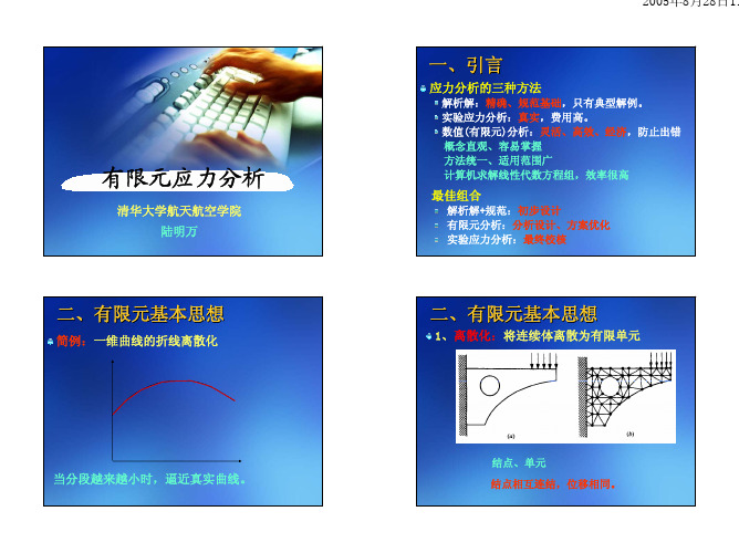
一、引言
应力分析的三种方法
解析解:精确、规范基础,只有典型解例。 实验应力分析:真实,费用高。 数值(有限元)分析:灵活、高效、经济,防止出错 概念直观、容易掌握 方法统一、适用范围广 计算机求解线性代数方程组,效率很高
有限元应力分析
清华大学航天航空学院 陆明万
最佳组合
解析解+规范:初步设计 有限元分析:分析设计、方案优化 实验应力分析:最终校核
三、有限元建模
● 板壳元与实体元连接: 按直法线(平面)假设加约束方程
实体单元 梁单元
按直法线假设加约束方程
- 1、下载文档前请自行甄别文档内容的完整性,平台不提供额外的编辑、内容补充、找答案等附加服务。
- 2、"仅部分预览"的文档,不可在线预览部分如存在完整性等问题,可反馈申请退款(可完整预览的文档不适用该条件!)。
- 3、如文档侵犯您的权益,请联系客服反馈,我们会尽快为您处理(人工客服工作时间:9:00-18:30)。
・ 封装技术与设备 ・
电子工业专用设备
!"#$%&’() *+, !-’.),+($. /,+0#.)1 23(#*3.)#,$(4
!"#$%& ’() *#!+#%& ’#,-.)&/ ,$ 0,& !)#!+ () 0&-#1,$#2,($3 ,$!-.0,$% 2"& 4/2 56 !.)& 7!.)& 893 2"& :$0 ; <)0 ; =2" 56 !.)& 7!.)& 889 #$0 *(/2>1(-0,$% !.)& 7!.)& 8889? @.) *)(!&// /,1.-#2,($ 0&1($/2)#2&/ 2"#2 !.)& 88 A(.-0 B& 2"& 1(/2 0&/2).!2,C& BD !(1*#),$% 2"& ,$’-.&$!& (’ 2"&/& 2")&& !.),$% *)(!&//&/ ($ EFEG )&-,#> B,-,2D? 82 ,/ #-/( ’(.$0 2"#23 ,$ !.)& 8 #$0 !.)& 88 # !&)2#,$ 0,/2),B.2,($ /2)&// A,2" 2D*,!#- !"#)#!2&),/2,!/ ,/ ’()1&0 ($ *#!+#%& B-(!+ A",!" !($/,/2/ (’ 4H .$,2 *#!+#%&/3 "(A&C&)3 $( /.!" !"#)#!2&),/2,!/ A#/ ’()1&0 ,$ /2&* !.)& 888? @.) ,$C&/2,%#2,($ A(.-0 B& B&$&’,!,#- 2( )&0.!,$% *#!+#%& ’#,-.)&/ #$0 ,$!)&#/,$% D,&-0/ 0.),$% *#!+#%,$% *)(!&//? 5’67+,018 I"&)1#- /2)&// #$#-D/,/J 2,($ /2)&//J 9 G)(!&// /,1.-#2,($ G#!+#%,$% *)(!&// ’-(A (’ 2",/ EFEG ,/ /"(A$ ,$ K,%.)& :? L,2" 2"& 0&1#$0 ’() *#!+#%&/ A,2" 1,$,#2.),M&0 /,M& #$0 ",%"&) ’.$!2,($#-,2D3 ",%">0&$/,2D <>5 &-&!> 2)($,! *#!+#%& "#/ B&!(1& 2"& 1#,$ 0&C&-(*1&$2 2)&$0 ,$ *#!+#%,$% 2&!"$(-(%D? @$& (’ 2"& /(-.2,($/ 2( )&#-,M& ",%" >0&$/,2D *#!+#%& ,/ 2( /2#!+ 1.-2,*-& !",*/ ,$ NON 0,)&!2,($ A,2",$ # /,$%-& *#!+#%&
封装体将承受多次热载荷。因此, 如果封装材料之间的热错配过大, 在芯片封装完成之前, 热应力 就会引起芯片开裂和分层。详细地研究了一种典型四层芯片叠层 ’() 封装产品的封装工艺流程 对芯片开裂和分层问题的影响。采用有限元的方法分别分析了含有高温过程的主要封装工艺中 产生的热应力对芯片开裂和分层问题的影响, 这些封装工艺主要包括第一层芯片粘和剂固化、 第 二、 三、 四层芯片粘和剂固化和后成模固化。在模拟计算中发现: ( 比较三步工艺固化工艺对叠 !) 第二步固化工艺是最可能发生失效危险的; ( 经过第一、 二步固化工 层 ’() 封装可靠性的影响, %) 艺, 封装体中发现了明显的应力分布特点, 而在第三步固化工艺中则不明显。 关键词: 热应力分析; 叠层芯片尺寸封装; 有限元分析; 分布应力; 工艺仿真 中图分类号: *+&"#,’文献标识码: . 文章编号: %""-$-#"(/!""#0%%$""-’$")
电子工业专用设备
!"#$%&’() *+, !-’.),+($. /,+0#.)1 23(#*3.)#,$(4
・ 封装技术与设备 ・
叠层 #$" 封装工艺仿真中的 有限元应力分析
刘彪 %, 王明湘 %, 林天辉
!
江苏苏州 $"%&$"* !"# 苏州大学电子信息学院,江苏苏州 $"%&$"; $# ’() 半导体!苏州*有限公司, 摘 要: 叠层 ’() 封装已日益成为实现高密度、 三维封装的重要方法。 在叠层 ’() 封装工艺中,
5$($)’ !-’&’() 6),’11 7(3-81$1 98 /3.:34$(4 /,+.’11 6$&#-3)$+( $( 3 6)3.:’0 ;<$% 6.3-’ /3.:34’
123 4567%8 9.+: ;5<=$>56<=%8 12+ *56<$?@A5!
( %, BAC6DEFA<E 7G ;5HD7AIAHED7<5HJ8 K77H?7L 3<5MADJ5EN !%#"!% O?5<6P !, KQ.+K2R+ /O?5<60 1ES, K@T?7@8 !%#"!%, )
? I",/ ,/ *(//,B-&
A,2" 2"& ’#/2 0&C&-(*1&$2 (’ A#’&) 2",$$,$% 2&!"$(-(%D? K.R,2/. "#/ 0&1($/2)#2&0 HS ! 1 2",!+ 0,&/ ’() # /2#!+&0 !",* /!#-& *#!+#%& 7EFEG9 #$0 ,/ A()+,$% ($ :H ! 1 2",!+ 0,&/
P:Q
? T(A&C&)3 0.),$% *)(!&// EFEG
*)(0.!2 /.’’&)/ ’)(1 1.!" ",%"&) ),/+ (’ 0,& !)#!+ ’#,-> .)&/ B&!#./& (’ 2",$$&) 0,&/? U()& ,$2&)’#!&/ B&2A&&$ -#D&)/ #$0 !",*/ #-/( B),$% 1()& !"#$!&/ (’ 0&-#1,$#> 2,($? 6$ ,1*()2#$2 /(.)!& !#./,$% 0,& !)#!+ () 0&-#1,> $#2,($ ,/ 2"& ",%" ,$2&)$#- /2)&// ,$0.!&0 BD 2"&)1#-(#0 0.),$% #//&1B-D *)(!&//? 8$ 2",/ A()+ # 2D*,!#- /2#!+&0 ’(.) >!",* *#!+#%& ,$ *-#/2,! B#-- %),0 #))#D 2D*& 7KI6SV<9 A#/ /2.0,&0? E"(A$ ,$ K,%.)& 4 ,/ # /!"&1#2,! ,--./2)#2,($3 ,$ A",!" 2A( K-#/" 0,&/3 ($& EW6U 75,&=9 #$0 ($& /*#!&) 0,& 75,&:9 #)& /2#!+&0 A,2",$ # /2#$0#)0 *#!+#%& "&,%"2 (’ 4?= 11? 5,& 2",!+$&// ,/ 4:S ! 1 #$0 0,& #22#!" 7569 2",!+$&// :H ! 1? X-&!2),!#- !($$&!2,($ ,/ *&)’()1&0 BD 6. A,)& #$0 /(-0&) B#-- 1&0,#2&0 BD !(**&) 1&2#-> -,M#2,($ ,$ # B,/1#-&,1,0& 2),#M,$& 7YI9 /.B/2)#2&? Y&> 2A&&$ 0,&/ () 0,& #$0 /.B/2)#2&3 2"&)& #)& B($0-,$&/ ’()1&0 BD &*(ZD () ’,-1 -,+& 56 #0"&/,C&/? 6-- !(1*(> $&$2/ #)& *)(2&!2&0 ,$ 1(-0 !(1*(.$0 7UF9? !" (总第 !"# 期) !"# $ %##&