爱德华产品说明书
爱德华 EST3 生命安全平台主显示界面说明书
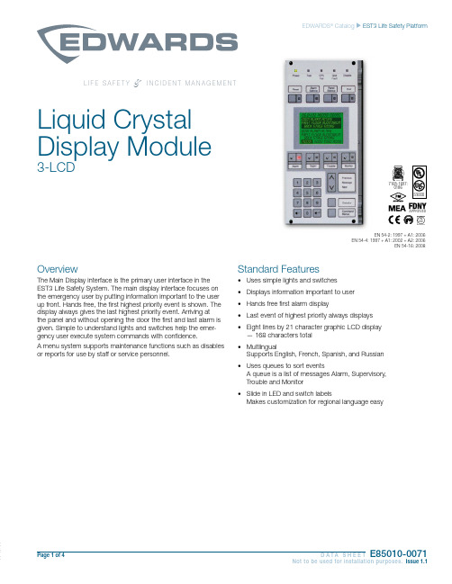
Page 1 of 4 D A T A S H E E TE85010-0071Not to be used for installation purposes. Issue 1.1EDWARDS ® Catalog u EST3 Life Safety PlatformL I F E S A F E T Y&I N C I D E N T M A N A G E M E N TOverviewThe Main Display interface is the primary user interface in the EST3 Life Safety System. The main display interface focuses on the emergency user by putting information important to the user up front. Hands free, the first highest priority event is shown. The display always gives the last highest priority event. Arriving at the panel and without opening the door the first and last alarm is given. Simple to understand lights and switches help the emer-gency user execute system commands with confidence.A menu system supports maintenance functions such as disables or reports for use by staff or service personnel.Standard Features• Uses simple lights and switches • Displays information important to user • Hands free first alarm display• Last event of highest priority always displays • Eight lines by 21 character graphic LCD display — 168 characters total • MultlingualSupports English, French, Spanish, and Russian • Uses queues to sort eventsA queue is a list of messages Alarm, Supervisory, Trouble and Monitor • Slide in LED and switch labelsMakes customization for regional language easySLiquid Crystal Display Module3-LCD0186APPROVEDEN 54-2: 1997 + A1: 2006EN 54-4: 1997 + A1: 2002 + A2: 2006EN 54-16: 2008Page 2 of 4 D A T A S H E E TE85010-0071Not to be used for installation purposes. Issue 1.1ApplicationThe 3-LCD module mounts to the local rail over the nodes Central Processing Unit Module (3-CPU). The 3-LCD module is optional in any network node.Ensuring information clarity the 3-LCD uses a backlit high contrast supertwist graphical display. Eight lines of 21 characters provide the room needed to convey emergency information in a useful format.The 3-LCD always displays the last highest priority event even when the user is viewing other message queues. Further message flexibility is provided with EST3’s message routing ability. Messag-es from a node can display at every node on the network or mes-sages can route to specific nodes only. Routing can be initiated at a specific time/shift change. There is no need to have messages display in areas that are not affected by an event.The 3-LCD can display messages in English, Spanish, French, and Russian. The bilingual display lets the operator select between either of two languages. Consult your representative for available language combinations.The EST3 system configures for Proprietary, Local or EN54 market operations. The mode of operation is selected through the System Definition Utility (SDU) which may adjust the following operations slightly to fit the system operation selected.LEDs and SwitchesFurther enhancing the 3-LCD user interface are easy to read and understand lights and switches. All functions are laid out in a logi-cal order. At the top of the 3-LCD are five system status LEDs. Here determining the general condition of the system is easy.Power LED : Green, on when AC power is on.Test LED : Yellow, on when any portion of the system (Group) isunder test.CPU Fail LED : Yellow, on when CPU stops running.Gnd Fault LED : Yellow, on when a ground exists on the system (group)Disable LED : Yellow, on when any point or zone is disabled by a user.Below the general status LEDs are located four, LED / Switch common controls. The versatility of EST3 allows system design-ers to define the features as affecting a domain (defined group of nodes) or as global (affects all nodes) across the network. This feature is very useful when configuring systems with multiple build-ings on one network. As an example, operating the reset in one building may have adverse effect in other buildings. With EST3 having operational differences between buildings on the same network is not a problem.Pressing Reset starts the system’s reset operation. The yellow LED has three flash rates during reset. The LED flashes fast during the smoke power down phase of reset, flashes slow during the re-start phase, and turns on steady for the restoral phase. The Reset LED turns off when the system is normal.Pressing Alarm Silence turns off all Notification Appliance Circuits defined as audible. The yellow LED turns on when silence is activevia the Alarm Silence switch or via alarm silence software timers.Pressing Panel Silence turns off the system’s internal audible signal. The yellow LED turns on when panel silence is active. The EST3 panel buzzer has user programmable signal rates for alarm, supervisory, trouble and monitor conditions.Pressing Drill turns on the drill LED and all signals sound evacua-tion. Drill does not activate city tie connections. Auxiliary relays willnot activate unless programmed to do so with drill.Liquid Crystal Display. In the normal condition the date and time plus a definable system title display on the LCD. The last line of the display gives an alarm history. This total equals the number oftimes the system has entered the alarm state from the normal state.When active events are on display, the LCD formats into fourlogical windows.In the system status window, the display shows the time and the status of active and disabled points.The current event window, lines 2, 3, 4 automatically display the first active event of the highest priority if the user has not taken control of the system. Once the emergency user takes control, thiswindow displays user message selections.The second line of the display shows system event information. Inthe example above the display shows the chronological number of the event (0001 is the first alarm) followed by the event type (Alarm Active). EST3 supports over 45 event type messages from which system designers choose. The last two lines of the current event window are custom programmable location message lines with space for 42 characters.The last event window shows the last highest priority event. This window is always displayed and updated automatically by the sys-tem. Here the emergency user can monitor the progress of a fire.system viewing the second alarm message iseasy, just press the NEXT key. The nextmessage scrolls into the current event window. The last highest priority event always remainson view. No matter what queue the user selects for viewing, the LCD always displays the most recent alarm. A new alarm event resounds the panel audible signal and appears immediately on display without overwriting information the user selected for view.The final window of the LCD the type status window shows the total number of active events by queue type. A is alarm, S is supervisory, T is trouble, and M is monitor. The number following each letter is the number of active events existing in each queue.EST3 breaks down event types into queues and automatically displays the first event of the highest priority type.Page 3 of 4 D A T A S H E E TE85010-0071Not to be used for installation purposes. Issue 1.1EN54 ComplianceEST3 has passed the British-based Loss Prevention Certification Board (LPCB) certified EST3 control panels and power supplies as having surpassed the requirements of the pivotal EN54 standard, parts two and four as well as part 16. LPCB Certificate #262ab In order to meet these standards, display and control functions have undergone slight modifications for the EN54 marketplace. These differences are highlighted below. All other control and annunciation features remain unchanged.Note: EN 54-2: 1997 + A1: 2006, EN 54-4: 1997 + A1: 2002 + A2: 2006, and EN 54-16: 2008.System Status LEDsPower LED (Green): on when DC power is on.Test LED (Yellow): on when any portion of the system (Group) is under test.CPU Fault LED (Yellow): on when CPU stops running (processor failures must be manually reset).Gnd Fault LED: Not available.Sounder LED (Yellow):flashing indicates fault on sounder circuit. Steady indicates a disabled sounder circuit.Disable LED (Yellow): on when any point or zone is disabled by a user (disabled conditions have priority over fault conditions).Switch FunctionsPressing Sounder On/Off turns off all sounder circuits defined asaudible. The yellow LED turns on when silence is activated via the Sounder On/Off or via the alarm silence software timers.See Page 2 for descriptions of Reset, Panel Silence, and Drill func-tions.Event QueuesFor EN54 compliance, EST3 configures for remote proprietary system operation. This requires that every event must be acknowl-edged by viewing them before the internal buzzer will silence. Thepriority order is Fire, Fault, Disable, Monitor.Priority order is alarm, supervisory, trouble, monitor. By usingqueues an emergency user does not waste time scrolling through a mixed event list looking for alarms or confusing an alarm mes-sage with other message types.EST3 configures for Remote proprietary system operation where every event must be acknowledged by viewing them before the internal buzzer will silence. Or the EST3 will configure for Local operation. Here the internal buzzer silences by pressing panel silence. If any events exist in queues that have not been viewedthe queue LED continues to flash informing the user of un-seen events.When all events in a queue are acknowledged or ‘seen’, theLED associated with the queue turns on steady. If a new event is added to the queue, the EST3 internal buzzer resounds and the queue LED flashes.EST3 allows device grouping into logical group zones. Here two or more alarm devices (such as detectors or pull stations) make up the zone. When a device in the zone activates, the LCD displays the zone description. Each zone only displays once, regardless of the number of devices active within the zone.DetailsTo display device information the user presses the Details key. The device with the lowestaddress displays in the first window.If multiple devices are active each is available for viewing by using the arrow associated with the Previous Message Next key andscrolling through the device list.expand beyond the Main Display interface by adding a Control Display Module and assigning features to its switch controls.For Maintenance users, the EST3 provides a smooth operatingmenu system providing powerful tools for system management, reports, and trouble shooting.Installation and MountingLIFE SAFETY & INCIDENT MANAGEMENTContact usPhone: 800-655-4497 (Option 4) Email: ************************ Website: 8985 Town Center PkwyBradenton, FL 34202© 2020 CarrierAll rights reserved.Engineering SpecificationThe system shall provide a user interface that displays system events in a text format, and supports basic common control LEDs and switches. The Common Control Switches and LEDs provided as minimum will be; Reset switch and LED, Alarm Silence switch and LED, Panel Silence switch and LED, Drill switch and LED. It must be possible to add additional common controls as required through the use of modular display units. The user interface must provide an LCD that will allow custom event messages of up to 42 characters. The interface must provide a minimum of eight lines by 21 characters and provide the emer-gency user, hands free viewing of the first and last highest priority event. The last highest priority event must always display and update automatically. Events shall be automati-cally placed in easy to access queues. It shall be possible to view specific event types separately. Having to scroll through a mixed list of event types is not acceptable. The total number of active events by type must be displayed. Visual indication must be provided of any event type which has not been acknowledged or viewed. It must be possible to cus-tomize the designation of all user interface LEDs and Switches for local language require-ments. It shall be possible to have a custom message for each device in addition to zone messages. Custom device messages must support a minimum of 42 characters each. Instructional text messages support a maximum of 1,000 characters each. The display shall be capable of displaying English, Spanish, French, or Russian messages. Technical SpecificationsCatalog Number3-LCDAgency Listings UL, ULC, FM, CE, LPCB, EN54*.LCD Display Eight lines by 21 characters backlit LCDMounting Two local rail spaces on top of 3-CPUCommon ControlSwitches and LEDsReset switch and LEDAlarm Silence switch and LEDPanel Silence switch and LEDDrill Switch and LEDAlarm Current42mAStandby Current40mA* EN 54-2: 1997 + A1: 2006, EN 54-4: 1997 + A1: 2002 + A2: 2006, and EN 54-16: 2008.3-LCDAdd suffix “-E” for EN54 compliant version.8 (.36)3-LKE UK English Label Kit.25 (.11)3-LKF French Label Kit.25 (.11)3-LKR Russian Label Kit.25 (.11)3-LKS Spanish Label Kit.25 (.11)Page 4 of 4D A T A S H E E T E85010-0071Not to be used for installation purposes. Issue 1.104-01-20。
爱德华产品、、技术手册

SIGA-PSIC SIGA-PSIC SIGA-HRSIC SIGA-HRSIC SIGA-HRSIC SIGA-HRSIC SIGA-CT1 SIGA-CT1 SIGA-CC1 SIGI271 SIGA-CT2 SIGA-IO SIGA-PSIC SIGA-PSIC SIGA-PSIC SIGA-HRSIC SIGA-HRSIC (可多重分支) SIGA-PSIC SIGA-PSIC SIGA-CT1 SIGA-CC1 SIGA-MCC1 SIGI271 SIGI271
EST3 系列火灾报警控制器(联动型)是爱德华公司为中、大型及超大型建设项目开发的、 是迄今为止最先进、最灵活的综合安全系统。 1.1.1 系统容量 1) 每个回路拥有 125 个分布智能特征探测器地址和 125 个分布智能特征模块地址。其中, 125 个分布智能特征探测器若配置继电器底座,还可增加 125 个输出点。 2) 1 台标准的 EST3 火灾报警控制器根据要求配置 1~10 个回路, 共 1,250 个分布智能特 征探测器地址和 1,250 个分布智能特征模块地址。 3) EST3 火灾报警控制器的系统容量可综合项目规模、不同建设时期等因素,按实际需要进 行灵活配置。对于超大型建设项目,可将 64 台火灾报警控制器组成 Peer-to-Peer 多重优先 令牌无主网络,系统可拥有 160,000 个地址。即 80,000 个分布智能特征探测器和 80,000 个分布智能特征模块。 1.1 EST3 智能火灾报警控制器(联动型) 一 火灾报警系统 2 1.1.2 布线方式
3) 系统电源 型号 3-PPS/M-230C(主电源) 3-BPS/M-230-E(辅助电源) 3-BBC/M-230-E(带充电功能的辅助电源) 配置 主电源监视卡是 LRM 轨道模块,占 1 个 3-CHAS7 轨道插槽,必需安装在 3-CPU3 旁。 辅助电源监视卡是 LRM 轨道模块,占用 3-CHAS7 上 1 个轨道插槽。 电源由开关电源模块和电源监视卡二部分组成,一块 3-CPU3 必须配置一套主电源,提供 2
爱德华三坐标技术协议
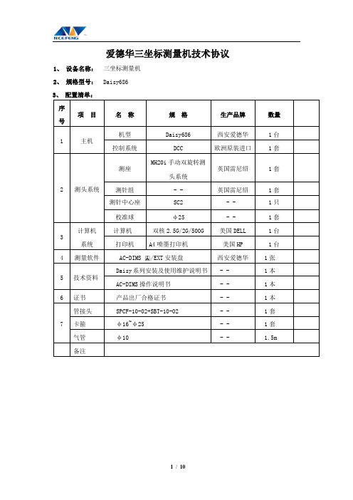
爱德华三坐标测量机技术协议1、设备名称:三坐标测量机2、规格型号:Daisy6863、配置清单:序号项目名称规格生产品牌数量1 主机机型Daisy686 西安爱德华1台控制系统DCC 欧洲原装进口1套2 测头系统测座MH20i手动双旋转测头系统英国雷尼绍1套测针组- - 英国雷尼绍1套测针中心座SC2 - - 1只校准球φ25 - - 1套3计算机系统计算机双核2.5G/2G/500G 美国DELL 1台打印机A4喷墨打印机美国HP 1台4 测量软件AC-DIMS □A/EXT安装盘西安爱德华1张5 技术资料Daisy系列安装及使用维护说明书- - 1本AC-DIMS操作说明书- - 1本6 证书产品出厂合格证书- - 1本7 管接头SPCF-10-02+SBT-10-02 - - 1套卡箍φ16~φ25 - - 1套气管φ10 - - 1.5m 备注4.2、性能指标:01、测头系统:RENISHAW MH20i手动双旋转可分度测头系统技术参数:TP20测力模块一个测头座分度机构:绕 A轴(水平轴)范围 0°~90°最小步距15°绕B轴(铅垂轴)范围±180°最小步距15°02、测针组:测针(mm):订货号型号材料测球直径长度杆直径有效长度数量(根)验收结果A-5003-0033 PS48R 红宝石测球/碳化钨杆 1 20 0.8 12.5 1A-5000-3603 PS2R 红宝石测球/不锈钢杆 2 20 1.4 14 1A-5000-4160 PS16R 红宝石测球/不锈钢杆 3 20 1.5 17.5 1A-5000-4161 PS17R 红宝石测球/不锈钢杆 4 20 1.5 20 1A-5000-7807 PS8R 红宝石测球/不锈钢杆 2 10 1 6 4A-5000-3604 PS1R 红宝石测球/不锈钢杆 3 10 1.5 7.5 1订货号型号材料直径长度数量(根)M-5000-7634 SE7 不锈钢杆 3 5 1M-5000-3647 SE4 不锈钢杆 3 10 1M-5000-3648 SE5 不锈钢杆 3 20 1M-5000-4162 SE6 不锈钢杆 3 30 1订货号型号材料中心尺寸有效长度数量(个)A-5000-3627 SC2 不锈钢杆7 7.5 1 03:校准器:标准球Φ25及万向球座T504:精度指标:长度计量系统:英国进口精密光栅尺分辨率:0.5μm;测量范围X×Y×Z: 600mm×800mm×600mm示值误差:MPEE≤2.4+L/300μm探测误差:MPEP≤2.4 m4.3、环境要求(详情见附件《三坐标测量机安装使用环境技术要求自检表》)01、温度:20±2℃ 1℃/h 1℃/m 2℃/24h02、湿度:40%-70%03、电源:220V±10%, 50HZ-60HZ04、气源:≥0.55MPa4.4、控制系统: DCC 控制器是德国MORA Metrology GmbH公司高性价比的运动控制器,能够广泛适用于各种工况的高性能、高可靠性的运动控制解决方案。
美国爱德华EST3消防报警系统产品说明书
0.23
图 B-8
4. 3-PPS/M-230 3-BPS/M-230
3-PPS/M 是主开关电源及其监视模板 一个节点机需要配置一个 主电源 每一个主电源需要一个电源监视模板 用于电源和机内总线的 连接 对电源的故障进行监视并将结果传送到系统 向电池充电并可根 据电池温度调节充电电流 在交流电断掉时起用电池并在电池输出电压 低于 21V 时断电保护电池
图 B-2
图 B-3
3-CPU 接线图
图 B-4 2. 3-LCD 3-LCD 是用户显示和操作界面模板 直接安装在 3--CPU 模板上 位于机箱内最上层部位 网络上全部 64 个节点只需安装一块 3-LCD 外形见图 B-5 机械安装见图 B-6 它包括如下部分 LCD 液晶显示屏 168 个字符的容量 带有节能型背景照明灯 自 动显示最初和最终报警
机内可选配置设备
EST3 采用的模块化设计是为了满足系统扩展的灵活性 在保证系 统性能和功能的前提下 达到最经济的配置 中央控制设备主要由以下 模板组成
1. 3-CPU 3-CPU 是 EST3 系统的中央处理单元模板 是系统的心脏 外形 见图 B-2 提供可选的内存扩展卡 RS232 和 RS485 通讯卡 RS232 提供网络与外部计算机或打印机的通讯接口 RS485 提供各节点机连 接成为带有优先权的 TOKEN RING 网络的通讯接口 接线见 B-4 安 装占用 2 个模板空间 见图 B-3
3-SSDC UL ULC 24 VDC 正常时250mA,报警时350mA 每卡100mA
自动 20V-19V 79 ohm 0.5 F 0-49 0-93% 非凝结 非饱和 数字式 环型或非环型 任意分支 每卡125个 每卡125个 每卡150个100A型的 0.75-1.5mm2
L.B. White 蒸汽热器产品说明书

2For over 65 years L.B. White has been America’s leading portable heat designer. With Midwestern manufacturing expertise we stand behind our craftsmanship, too. So much so, we back our products with a two-year limited warranty—the first and only of its kind in the industry*.Get more than heat from L.B. White.WE STAND BEHIND QUALITY.*Excludes Sunblast Tank Tops12’ extendable ducting (optional-part #26346 [12”] for 80 & 170 PREMIER ®8080 DF 170170 DF 350Premier ®Ductable unit heatersFuel Type(s) available: LP & Dual FuelThese versatile heaters are great for construction sites*, where low noise or an enclosed flame are important. Premier® heaters can be used to provide heat or simple air circulation inside, or be ducted in from the outside.Quiet Simple to read diagnosticsEnclosed flame promotes Included:20’ Remote ThermostatRegulator Gas Hose2®125170170 Ultra170N170N Ultra 400400 Ultra- T hermostatic temperature control (170 and 400 models)- Variable heat output promotes fuel savings- Dependable electronic spark ignition--Variable output control formaximum fuel efficiencyplate for longest lifediagnostic light for convenienttroubleshooting*250,000 - 400,000 BTU/H on LP.Tradesman®Forced Air LP/NG HeatersFuel Type(s) Available: LP, NG, & Dual Fuel Engineered to deliver reliable, directional heat, the Tradesman® heaters feature a unique 3-trial ignition system, the industry’s heaviest gauge combustion chamber and burner plate, and Self Diagnostic Service Saver models for convenient trouble-shooting.3- Dependable dual-prong electronic spark ignition - Comfort control thermostat- B uilt in air diagnostic system for troubleshooting ease - Fuel gauge indicates remaining run time - Durable composite fuel fittings for max life - Threaded drain plug- Wheels and handles for maneuvering (K125 and up)- CSA certified for U.S. and CanadaTradesman ® kForced Air HeatersFuel Type(s) available: kerosene*Provides instant, directional heat when using gas is not convenient, or a self-contained fuel source is desired. A dependable dual-prong electronic spark ignition, heavy duty enclosed motor, and long lasting composite fuel fittings are just a few of the features that provide a long life.Auxiliary 110V power receptacle(125K thru 400K)Temperature display and thermostat control fuel usageIncludes pressure gauge for easy serviceability (K75 thru K210)*Kerosene, #1 and #2 Diesel or #1 fuel oil.4- Easy to transport (single point lifting bale and bottom fork pockets for easy maneuverability)- Quiet burn with high CFM- Can accommodate up to 100’ of ducting - S eparate diagnostic light panels for burner and rest of unit- Remote thermostatic control available - Rugged, urethane wheels don’t go flat, yet absorb bumps like pneumatic tires- O-T L certified for U.S. and CanadaForeman ®Indirect-fired heatersFuel Type(s) available: Dual Fuel & DieselThe vented Foreman® heater is ideal for providing dry, clean, heat into insulated spaces, work areas, warehouses or anywhere clean air is needed. L.B. White’s Foreman® heater features an airrecirculating option, choice of dual or single air output with optionalducting, and easy diagnostics.Two 12” ducts standard or one16” duct sold separatelySwitch between LPG and NG with push lever on DF unit Air recirculation option; just add 20” duct16” Duct Adapter (#30902)Chimney, Raincap(Foreman 500s & 750 DF: #30161, #30162Foreman 750 Oil: #30161A, #30162A)Thermostat (#30125)accessories:5boss ™direct-fired heatersFuel Type(s) available: Dual FuelBoss™ heaters combine 99% fuel efficiency with the ability to distribute heat into largeconstruction or industrial spaces. Loaded with features that benefit owner and operator, thesedirect-fired heaters are engineered to be job site tough and work ashard as you do.1000 DF QuickSwitch TMControl panel featuring and diagnostic light- No parts or downtime to change fuel, confirm onsite voltage, or manage heat output - Truly portable with handle, no-flat wheels, and standard door fit- Indoor/outdoor rated and rust resistant - O-T L certified for U.S. and Canada10-sided case for easy inside-out accessStackable6- Ideal for heavy industrial and rental use - Direct-fired = 99.97% fuel efficiency- 360° heat output (200 Plus and 250 models)- Heavy duty, one piece barrel- Unique top design provides superior distribution of heat - CSA certified for U.S. and Canada (Norseman 200 Plus Only)Heaviest gauge steel body Adjustable shut-off Norseman ™Convection heatersFuel Type(s) available: LPThese heavy duty convection heaters feature cast iron burners and heavy gauge steel bodies. Norseman™ heaters are ideal for rental or frequent usage on construction sites, or anytime electricity is not available.required7- Lightweight for easy maneuverability- Variable heat (225 Plus)- Direct-fired = 99.97% fuel efficiency - Enclosed stainless steel burner provides superior wind resistance - 360° heat output- One piece barrel for strength and durability- No assembly required- CSA certified for U.S. and Canada100N Plus 225 PlusWorkman ™Convection heatersFuel Type(s) available: LP & NGThese standard duty convection heaters feature adjustable output control to save fuel, and a unique top design for superior heatdistribution. Workman™ heaters provide 360° heating and don’t require electricity.Adjustable output control for maximum fuel efficiency Unique top design provides superior distribution of heatNo electricity required8- Lightweight for easy maneuverability - Piezo ignition- Direct-fired = 99.97% fuel efficiency- T ip over switch shuts product down for safety - Works with standard 20 lb. cylinder - ETL certified for U.S. and Canada3535,000Sun Blast ®flat panel radiant heaterFuel Type(s) available: LPThis flat panel radiant is great for spot heating large areas using its tall profile. Easy to move around with its high handle and wheels, this Sun Blast® radiant heater has quiet operation. Radiant heaters heat like the sun, heating objects not the air.Directional heat with large foot print Folding handle and wheelsfor easy transportNo electricity required9- Lightweight for easy maneuverability - Piezo pilot ignition- Improved design over competitive models prevents carbon build-up for longer run time - Direct-fired = 99.97% fuel efficiency- T ip over switch shuts product down for safety - High temperature paint- ETL certified for U.S. and CanadaSun Blast ®round radiant heatersFuel Type(s) available: LP & NGProvides 360° radiant heating and doesn’t require electricity. Their rugged construction makes them durable for any construction site. Radiant heaters heat like the sun, heating objects not the air.360° heat output High handle and wheels for easy transportNo electricity required10- CSA certified high wind resistant burner - Variable BTU output- Front and back protective grill - Shuts off with loss of flame- Fit on your standard 20 lb. LP cylinder - Manual ignition- No electricity required- Direct-fired = 99.97% fuel efficiency - Quick connect P.O.L. tank connection- CSA certified for U.S. and CanadaSun Blast ®tank top Radiant HeatersFuel Type(s) available: LPTank top heaters easily fit on your standard 20 lb. LP tank and provide great spot heat.Radiant heaters heat like the sun, heating objects not the air. Units are available in single or double head models and don’t require electricity.Tip over safety switch Hand-wheel to reduce connection time No electricity required11- Lightweight steel and heavy duty cast iron models - Manual or pilot light- Assembled handle lengths from 17.5 to 41”- No regulator needed for Torchman ™ models- Can use year round- Ships in economical quantities of 4 or 8- E TL certified for Canada (Torchman ™ SV and 500 only)Torchman ™ SV Torchman ™ 500Bertha ™ 500Industrial 250Industrial 365N 300,000500,000500,000250,000365,000Handheld TorchesTorchman ™, bertha ™, & industrialFuel Type(s) available: LP & NGDesigned for a variety ofapplications, L.B. White heavy duty torches meet some of the industry’s toughest specs. Ideal for thawing pipes, burning brush, roofing, and more.Cast iron burner on Bertha &Torchman SV, Industrial 250,Extra handle (part #25791) for maneuverability available onAccessories gas hose1213The number of Btu/h may vary from the chart due to building configurations, materials, and weather variables.4,000 5,320 10,640 15,960 21,280 26,600 31,920 37,240 42,560 8,000 10,640 21,280 31,920 42,560 53,200 63,840 74,480 85,120 12,000 15,960 31,920 47,880 63,840 79,800 95,760 111,720 127,680 16,000 21,280 42,560 63,840 85,120 106,400 127,680 148,960 170,240 20,000 26,600 53,200 79,800 106,400 133,000 159,600 186,200 212,800 24,000 31,920 63,840 95,760 127,680 159,600 191,520 223,440 255,360 28,000 37,240 74,480 111,720 148,960 186,200 223,440 260,680 297,920 32,000 42,560 85,120 127,680 170,240 212,800 255,360 297,920 340,480 36,000 47,880 95,760 143,640 191,520 239,400 287,280 335,160 383,040 40,000 53,200 106,400 159,600 212,800 266,000 319,200 372,400 425,600 44,000 58,520 117,040 175,560 234,080 292,600 351,120 409,640 468,160 48,000 63,840 127,680 191,520 255,360 319,200 383,040 446,880 510,720 52,000 69,160 138,320 207,480 276,640 345,800 414,960 484,120 553,280 56,000 74,480 148,960 223,440 297,920 372,400 446,880 521,360 595,840 60,000 79,800 159,600 239,400 319,200 399,000 478,800 558,600 638,400 64,000 85,120 170,240 255,360 340,480 425,600 510,720 595,840 680,960 68,000 90,440 180,880 271,320 361,760 452,200 542,640 633,080 723,520 72,000 95,760 191,520 287,280 383,040 478,800 574,560 670,320 766,080 76,000 101,080 202,160 303,240 404,320 505,400 606,480 707,560 808,640 80,000 106,400 212,800 319,200 425,600 532,000 638,400 744,800 851,200 84,000 111,720 223,440 335,160 446,880 558,600 670,320 782,040 893,760 88,000 117,040 234,080 351,120 468,160 585,200 702,240 819,280 936,320 92,000 122,360 244,720 367,080 489,440 611,800 734,160 856,520 978,880 96,000 127,680 255,360 383,040 510,720 638,400 766,080 893,760 1,021,440 100,000 133,000 266,000 399,000 532,000 665,000 798,000 931,000 1,064,000 104,000 138,320 276,640 414,960 553,280 691,600 829,920 968,240 1,106,560 108,000 143,640 287,280 430,920 574,560 718,200 861,840 1,005,480 1,149,120 112,000 148,960 297,920 446,880 595,840 744,800 893,760 1,042,720 1,191,680 116,000 154,280 308,560 462,840 617,120 771,400 925,680 1,079,960 1,234,240 120,000 159,600 319,200 478,800 638,400 798,000 957,600 1,117,200 1,276,800Cubic FeetRISE IN TEMPERATURE6°C / 10°F 11°C / 20°F 17°C / 30°F 22°C / 40°F 28°C / 50°F 33°C / 60°F 39°C / 70°F 44°C / 80°FWHAT BTU/H IS NEEDED TO HEAT A GIVEN AREA?1. Multiply room length x width x height to determine total cubic feet.2. L ocate desired rise in temperature.Example: Room is 10°C / 50°F, desired temperature is 21°C / 70°F = 11°C / 20°F rise in temperature3. Read Btu/h500 gallon tank - 1 heater per tank 1000 gallon tank - 2 heaters per tank WHAT size gas supply is needed for my heater?fit to your job site411 Mason Street • Onalaska, Wisconsin 54650(800) 345-7200 - (608) 783-6115 fax /LBWhiteCompanyBased in Onalaska, WI, L.B. White Company is America’s leading designer, manufacturer and marketer of propane, natural gas and kerosene heaters for construction, agricultural, tent and greenhouse environments.Founded in 1952, L.B. White offers over 65 years ofleadership in heating design and manufacturing expertise.Through the course of the company’s history,L.B. White has established a significant leadership position in markets around the world by delivering innovative products and quality service that meet the evolving needs of ourcustomers.Customer Service:Phone: 608-779-6100Email:***************************Technical Support:Phone: 608-779-6101Email:***********************Online Resources:For frequently asked questions, service guides,troubleshooting and maintenance videos, or to find the closest service center to you, visit 。
平行双闸板阀特点

1. WEIR公司简介WEIR公司是一家著名的阀门生产厂家,为客户提供一流质量的阀门和配套设备,它的产品广泛应用于核电,火电,石油天然气和化工行业,WEIR在阀门及配件方面拥有特殊的专长和丰富的经验,质量管理体系通过ISO9000认证。
WEIR公司的HOPKINSINS高压平行双闸板阀,采用特殊的结构设计,密封性好(零泄漏),开关无磨损,动作速度快,需要驱动力小,在全世界得到广泛应用,在中国电力和石化的高压紧急切断\紧急防空联锁控制中发挥了关键性的作用.世界上仅有 Edward爱德华,美国阀门技术VTI和英国德康DECON几个品牌与HOPKINSONS 具有同样的阀门结构和性能, 别的品牌均达不到这种技术水平.H OPKINSONS: 平行双闸板阀,单向阀,Y型截止阀,口径:2″-30″, 压力等级:600#-4500#。
2.WEIR公司的平行双闸板阀技术特点:阀板沿滑道升降,密封面无磨损2.1 主要性能a. 关断严密,可达到ANSI B16.104规定的CLASS VI级和API标准规定的零泄露b. 可双向严密关断:ANSI B16.104 Class VIc. 压力自密封结构,随着压力升高,密封性能更好d. 闸板沿滑道升降,密封面无磨损,可长期保持ANSIB16.104 Class VI关断e. 采取阀板自清理结构,阀板面不易黏结污物f. 对易凝结的介质(例如硫磺)可采用蒸汽吹洗阀板的结构g. 采用防火结构设计和防阀杆吹出结构h. 对腐蚀性介质,阀体NACE处理(NACE MR-01-7)i. 动作时间快速:可满足用户的任意特殊要求j. 由于平行阀板之间采用弹簧平衡,阀门不受介质热胀冷缩影响,不会产生卡住的现象。
2.2 重要特点a. 压力自密封结构 和温度自适应阀座结构b. 随动流道避免了流体旋涡引起的的震动,保证阀门长期稳定可靠运行,减少了脏物的沉积。
c.特殊的阀内腔和滑道设计使得阀门开关阻力少于其他类型的阀门,如球阀和楔型闸阀等,阀门开关不磨损密封面,动作快速,长期密封等级不变2.3 与楔型闸阀的比较楔型闸阀靠挤压变形而达到密封效果,开关需要推动力矩大,阀板面磨损严重,需要定期更换阀座和阀板,开启状态阀板受冲击震动严重,而这些问题在对于平行双闸板阀来说都得到了很好的解决,使用寿命长,密封效果优于楔型闸阀。
AVM58绝对值编码器接线说明书

预置输入
计数方向的输入选择
输入
Ue ^
过滤器 逻辑 下拉
IN
Ue ^
上推 过滤器 逻辑
时钟输入(2线)
光电隔离的时钟输入符合标准RS 422接口.控制模块时钟同步数据在电气接口与编码器之间传输,在"clock+" 与"clock-"之间接120欧电阻已在出厂时完成.
脉冲图通地袍换时钟数据线来移动.
9213
D1: Ø6 mm, D2: Ø6 mm
9401
D1: Ø6 mm, D2: Ø6 mm
9402
D1: Ø6 mm, D2: Ø6 mm
9404
D1: Ø6 mm, D2: Ø6 mm
9409
D1: Ø6 mm, D2: Ø6 mm
KW
罩和套件 9300and9311-3
ø58 ø50h7 ø6h7
0.5 + 0.1 53.5
3 x 120˚ ø58 ø52 ø36f8 ø10h7
0.5 + 0.1 53.5
3 x 120˚
ø58 ø50x 120˚ ø58 ø52 ø36f8 ø10h7
0.5 + 0.1 54
3 x 120˚
–
命名/规格特性
订货代码
D1: Ø10 mm, D2: Ø10 mm
9401
D1: Ø10 mm, D2: Ø10 mm
9404
D1: Ø10 mm, D2: Ø10 mm
9409
D1: Ø10 mm, D2: Ø10 mm
KW
塑 料
9101, 10
橡 胶
9102, 10
重量 转速
约. 460 g (组合 1) 约. 800 g (组合 2) 最 大. 6000 min-1
爱德华(Edwards)家庭安全灯系列(HSL Series)产品说明书
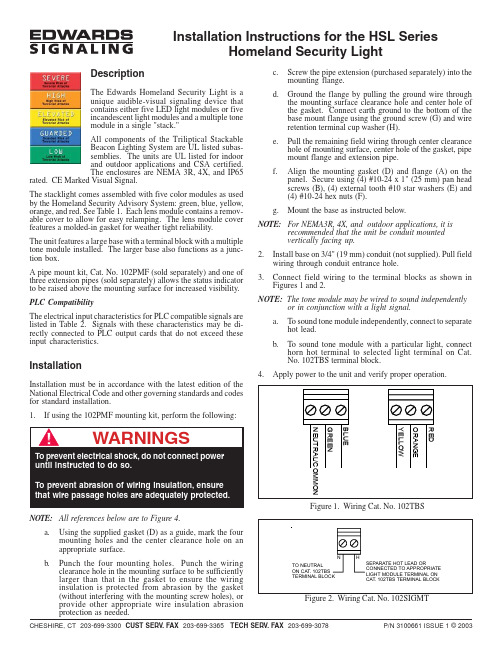
P/N 3100661 ISSUE 1 © 2003CHESHIRE, CT 203-699-3300 CUST SERV . FAX 203-699-3365 TECH SERV . FAX 203-699-3078Installation Instructions for the HSL SeriesHomeland Security LightDescriptionThe Edwards Homeland Security Light is a unique audible-visual signaling device that contains either five LED light modules or five incandescent light modules and a multiple tone module in a single "stack."All components of the Triliptical Stackable Beacon Lighting System are UL listed subas-semblies. The units are UL listed for indoor and outdoor applications and CSA certified.The enclosures are NEMA 3R, 4X, and IP65rated. CE Marked Visual Signal.The stacklight comes assembled with five color modules as used by the Homeland Security Advisory System: green, blue, yellow,orange, and red. See Table 1. Each lens module contains a remov-able cover to allow for easy relamping. The lens module cover features a molded-in gasket for weather tight reliability.The unit features a large base with a terminal block with a multiple tone module installed. The larger base also functions as a junc-tion box.A pipe mount kit, Cat. No. 102PMF (sold separately) and one of three extension pipes (sold separately) allows the status indicator to be raised above the mounting surface for increased visibility.PLC CompatibilityThe electrical input characteristics for PLC compatible signals are listed in Table 2. Signals with these characteristics may be di-rectly connected to PLC output cards that do not exceed these input characteristics.InstallationInstallation must be in accordance with the latest edition of the National Electrical Code and other governing standards and codes for standard installation.1.If using the 102PMF mounting kit, perform the following:c.Screw the pipe extension (purchased separately) into the mounting flange.d.Ground the flange by pulling the ground wire through the mounting surface clearance hole and center hole of the gasket. Connect earth ground to the bottom of the base mount flange using the ground screw (G) and wire retention terminal cup washer (H).e.Pull the remaining field wiring through center clearance hole of mounting surface, center hole of the gasket, pipe mount flange and extension pipe.f.Align the mounting gasket (D) and flange (A) on the panel. Secure using (4) #10-24 x 1" (25 mm) pan head screws (B), (4) external tooth #10 star washers (E) and (4) #10-24 hex nuts (F).g.Mount the base as instructed below.NOTE:For NEMA3R, 4X, and outdoor applications, it isrecommended that the unit be conduit mounted vertically facing up.2.Install base on 3/4" (19 mm) conduit (not supplied). Pull field wiring through conduit entrance hole.3.Connect field wiring to the terminal blocks as shown in Figures 1 and 2.NOTE: The tone module may be wired to sound independentlyor in conjunction with a light signal.a.To sound tone module independently, connect to separate hot lead.b.To sound tone module with a particular light, connect horn hot terminal to selected light terminal on Cat.No. 102TBS terminal block.4.Apply power to the unit and verify proper operation.NOTE:All references below are to Figure 4.a.Using the supplied gasket (D) as a guide, mark the four mounting holes and the center clearance hole on an appropriate surface.b.Punch the four mounting holes. Punch the wiring clearance hole in the mounting surface to be sufficiently larger than that in the gasket to ensure the wiring insulation is protected from abrasion by the gasket (without interfering with the mounting screw holes), or provide other appropriate wire insulation abrasionprotection as needed.Figure 1. Wiring Cat. No. 102TBSP/N 3100661 ISSUE 1MaintenanceLight Source Replacement 1.Loosen captive screws and remove cover of affected lens module.2.Remove the light source assembly from the lens module.3.Install new light source assembly ensuring that the four prongs on the PC board are aligned with the plug located in the back of the lens module.illustration purposes only)4.Replace lens cover and secure using two captive screws.CleaningThe lens surfaces should be periodically dusted and cleaned with a dry soft clean cloth to maintain optimum light visibility. If necessary, the outside of the lens may be cleaned with water and a mild detergent on a well rung-out, soft, clean cloth.Figure 4. Optional 102PMF Mounting Kit AssemblyP/N 3100661 ISSUE 1Table 1. SpecificationsElectrical Manufacturers Replacement Lamp Life (hours) Catalog No.Ratings Lamp Ratings Lamp Calculated#Projected##Base Units102TBS-G124V DC, 1.75A+N/A N/A N/A N/A102TBS-N5120V AC, 0.60A+Optional Pipe Mount Flange102PMF N/A N/A N/A N/A N/AOptional Extension Pipes102MP-4N/A N/A N/A N/A N/A102MP-10N/A N/A N/A N/A N/A102MP-15N/A N/A N/A N/A N/AHorn Assembly102SIGMT-G124V DC, 0.05A N/A N/A N/A N/A102SIGMT-N5120V AC, 0.07ALens Modules102LM-*N/A N/A N/A N/A N/ALight Sources102LS-SIN-G124V DC, 0.32A10 Watts Ind. Trade 30310,000--102LS-SIN-N5120V AC, 0.08A10 Watts50LMP-10W2,500--102LS-SLEDA-G1**24V DC, 0.062A--N/A100,000--102LS-SLEDB-G1**102LS-SLEDG-G1**102LS-SLEDR-G1**102LS-SLEDW-G1**102LS-SLEDA-N5**120V AC, 0.022A--N/A100,000--102LS-SLEDB-N5**102LS-SLEDG-N5**102LS-SLEDR-N5**102LS-SLEDW-N5**+Currents shown are for a stackable indicator with 5 light modules.*Signifies lens module color (A - amber/orange, B - blue, C - clear, G - green, R - red, Y - yellow)**Signifies lens and LED module color (A - amber/orange, B - blue, G - green, R - red) NOTE: LED light sources must be used with thecorresponding color lens module (e.g., a blue LED light source, 102LS-SLEDB-G1, must be used with a blue lens, 102LM-B). For yellowmodules, use the 102LS-SLEDW light source.#At nominal operating voltage.##Projected lamp life based on manufacturer's calculated lamp life @ 65 fpm and 50% duty cycle.Table 2. PLC CompatibilityUnit input Maximum leakage Continuous on Peak current Cat. No.voltage*current (mA)current (mA)inrush/duration (A/ms**) 102SIGMT-G124V DC5500.24/0.2102SIGMT-N5120V AC5700.35/0.5102LS-SIN-G124V DC25320.36/1102LS-SIN-N5120V AC25800.15/8102LS-SLED( )-G124V DC5650.07/1102LS-SLED( )-N5120V AC5250.09/8*All AC volts at 60 Hz**Amps/millisecondsP/N 3100661 ISSUE 1。
- 1、下载文档前请自行甄别文档内容的完整性,平台不提供额外的编辑、内容补充、找答案等附加服务。
- 2、"仅部分预览"的文档,不可在线预览部分如存在完整性等问题,可反馈申请退款(可完整预览的文档不适用该条件!)。
- 3、如文档侵犯您的权益,请联系客服反馈,我们会尽快为您处理(人工客服工作时间:9:00-18:30)。
65 欧姆
<5%
75mA
75mA
893mA
1544mA
15W
30W
1 个导轨空间
1 个导轨空间
电流电压 线间最大电阻 线间最大电容
频闪灯电路参数 24V,3.5A 50 欧姆 0.33μF
8. 控制开关/显示模板 控制开关/显示模板是一组带有发光二极管(LED)显示和触摸式控制开关的用户 操作界面。它包括下表中的全部型号。它们通过 3-LDSM 模板,或 LRM 模板与 3-CPU 实现机械连接和电气连接。 安装见图 B-16。
◇状态指示器: 指示交流电源、测试模式、CPU、接地以及探测器连接的当前状 态。
◇事件队列:提供 4 个独立的事件队列,每个队列包括 500 条事件。一个报警队 列,一个检测队列,一个故障队列,一个监视队列。每个队列都有一个黄色 LED 灯作为事件指示,任一个事件均被自动分类并存储在上述四种队列之一中。在得 到确认前 LED 一直保持闪烁,在所有事件被确认后 LED 才停止闪烁,保持亮起。 ◇命令菜单:用户按下按钮可调出命令菜单,这些命令包括:状态、使能、关掉、 激活(启动)、复位(停止)、控制输出、报告和编程。当然需要用户输入一个正确
型号 3-ASU/FT 3-ASU/4 3-ASU 3-FTCU 3-ASUMX/12 3-ASUMX/32
图 B-7
说明
带 CHASS,带麦克风,带电话,带电源卡
带 CHASS,带 4 个模块空间,带麦克风,带电源卡
带麦克风,带电源卡
带电话,带电源卡(必须与 3-ASU 一起使用)
YU 语音内存扩展卡,提供 12 分钟信息时间
图 B-16
型号 3-LDSM 3-24R 3-24Y 3-24G 3-12SR 3-12SY 3-12SG 3-12RY 3-12/2Y 3-12/RY 3-12/S1GY
3-12/S1RY
3-12/S2Y 3-6/3S1G2Y
3-6/3S1GYR
数据
说明 控制显示模板的总线接口模板 24 个红色发光二极管显示模板 24 个黄色发光二极管显示模板 24 个绿色发光二极管显示模板 12 个薄膜开关和 12 个红色发光二极管模板 12 个薄膜开关和 12 个黄色发光二极管模板 12 个薄膜开关和 12 个绿色发光二极管模板 12 个红色和 12 个黄色发光二极管显示模板 2 个为一组共 12 组黄色发光二极管 1 个红色和 1 个黄色为一组共 12 组发光二极管 12 个开关,每个开关带有 1 个绿色 1 个黄色发光二极 管 12 个开关,每个开关带有 1 个红色 1 个黄色发光二极 管 12 个开关,每个开关带有 2 个黄色发光二极管 3 个开关为 1 组,每个开关带有 1 个发光二极管,颜 色为 1 个绿色 2 个黄色。共六组 18 个开关 3 个开关为 1 组,每个开关带有 1 个发光二极管,颜 色为 1 个绿色 1 个黄色 1 个红色。共六组 18 个开关
语音内存扩展卡,提供 32 分钟信息时间
4. 3-PPS/M-230,3-BPS/M-230 3-PPS/M 是主开关电源及其监视模板。一个节点机需要配置一个主电源。每一个 主电源需要一个电源监视模板。用于电源和机内总线的连接;对电源的故障进行 监视并将结果传送到系统;向电池充电并可根据电池温度调节充电电流;在交流 电断掉时起用电池并在电池输出电压低于 21V 时断电保护电池。 3-BPS/M 是辅助开关电源及其监视模板,一个辅助电源需要配置一个辅助电源监
机内可选配置设备
EST3 采用的模块化设计是为了满足系统扩展的灵活性,在保证系统性能和 功能的前提下,达到最经济的配置。中央控制设备主要由以下模板组成:
1.3-CPU 3-CPU 是 EST3 系统的中央处理单元模板,是系统的心脏。外形见图 B-2。提供可 选的内存扩展卡、RS232 和 RS485 通讯卡。RS232 提供网络与外部计算机或打印 机的通讯接口;RS485 提供各节点机连接成为带有优先权的 TOKEN RING 网络的 通讯接口。接线见图 B-4。安装占用 2 个模板空间,见图 B-3。
它也是 LRM 模板,任一种控制/显示模板均可安装在它的前面。
技术数据
型号 认证 工作电压 工作电流 向普通探测器供电能力 系统编址方法 回路输出电压 回路最大电阻 最大回路电容 工作温度 相对湿度 通讯格式 接线方法 可接模块数量 可接探测器数量 可接普通探测器数量
3-SSDC UL,ULC 24 VDC 正常时 250mA,报警时 350mA 每卡 100mA
3.快速的系统响应时间 可以肯定地说,火灾报警工业领域内一直在不断追求缩短系统响应时间,实际上, 现存大多数厂家的系统在小负荷配置下,也得在报警后 12 秒钟内收到报警信号。 但 EST3 现在却又一次大大减短了系统响应时间:回路内全负荷响应时间为 750 毫秒(不到 1 秒),网络全负荷为 3 秒,比现行工业标准要短得多。
7.多通道音频传输系统 目前只有 EST3 能够通过一对双绞线同时传输 8 种数字语音信息,为紧急广播和 消防电话提供高质量的数字式音频信号,与带有液晶显示屏的火警电话控制单元 配合使用,EST3 提供了一种全新的火灾紧急通讯系统。
8.简单直观的操作面板 EST3 的用户几乎不必再接受培训即可进行操作,EST3 操作界面的特点是:特大 (168 字符)LCD 显示,持续的最初和最终报警显示,文字或图示的薄膜按钮,国 际标准的操作符号,可更换的提示标签,节约能源的背景照明灯光。
6.支持智慧型特征系列产品 EST3 完全支持新一代智慧型特征系列(Signature Series)产品。具有探头连线 自动成图(包括“T”型接法)。自动为探头模块分配地址。自动按时改变探测器 灵敏度。支持报告生成。支持条形码输入地址。回路线上采用广播式寻访,大大 的减少了通讯数据量,使探测器间的连线使用普通线(非双绞线)即可。
间、其它所有层的紧急广播,另有 2 个通道备用。可存储 2~34 分钟的语音信息, 可循环播放多国语言,带有话筒单元。
3.1 3-ASU/FT 3-ASU/FT 是带有消防电话的音频控制单元模板,除具有与 3-ASU 相同的性能以 外,带有 168 字符的 LCD 液晶显示屏。在上半部可显示 20 个呼叫信息,在下半 部显示最多 5 部电话同时接通的信息。外形见图 B-7。接线应用见图 B-8。
视模板,其功能与主电源监视模板相同,只是无电池充电功能。 它也是 LRM 模板,任一种控制/显示模板均可安装在它的前面。安装见图 B-9。 接线见图 B-10。
图 B-8 图 B-9
性能参数表
型号
3-PPS/M 3-BPS/M 3-PPS/M-230 3-BPS/M-230
认证
UL,ULC
输入电压 输入电压频率 输入电流 A 最低可用电压 V 输出电压 V 输出总电流 A 端子可用线型 输出保护 最大电池充电能力 电池放电保护电压 电池监视报警电压 接地故障测试 安装空间要求
的密码。 ◇扩展信息显示:按下“扩展信息”开关,系统列表显示激活区域内设备的详细
信息。当多个设备激活时,可按下前/后按钮滚动显示。
图 B-4
图 B-5
图 B-6
3. 3-ASU,3-ASU/4,3-FTCU,3-ASU/FT 3-ASU 是音频控制单元模板,提供 8 个通道的同步数字通信信号,提高了音频信 号的容量和质量。8 个通道可分别应用于火警层、火警上下相邻层、电梯、楼梯
图 B-2
图 B-3
2. 3-LCD 3-LCD 是用户显示和操作界面模板,直接安装在 3--CPU 模板上,位于机箱内最 上层部位。网络上全部 64 个节点只需安装一块 3-LCD。外形见图 B-5。机械安装 见图 B-6。它包括如下部分:
◇LCD 液晶显示屏:168 个字符的容量,带有节能型背景照明灯。自动显示最初 和最终报警。
4.高度的运行可靠性 运行的可靠性对任何一个生命与财产安全系统都是至关重要的,EST3 对系统中 包含的所有电路时刻进行自动监测,对系统中安装的重要部件时刻进行自动诊 断。如果系统监测到设备故障,立即在操作面板上给出故障报警。如果监测到网 络任何部位发生断路,立刻对断开部分进行重组,将其重新配置成为一个子网络。 即使在网络线短路的情况下,也能正常工作。环境自动补偿功能使得系统能够根 据探测器污染状况,自动修正报警设定值。加上复合探测技术的运用,EST3 的 误报率几乎降低至零。
自动 20V-19V 79 ohm 0.5 μF 0-49 ℃ 0-93% 非凝结(非饱和) 数字式 环型或非环型(任意分支) 每卡 125 个 每卡 125 个 每卡 150 个 100A 型的
端子用线
0.75-1.5 平方毫米
6. 3-IDC8/4 3-IDC8/4 是传统意义的普通卡模板,提供 8 个 Class B 回路,监视两线制探测 器和干触点设备,其中 4 个回路可用作广播通道。安装占用 1 个导轨空间。
AC120V
AC230V
50-60Hz
2.0
1.0
96
184
24Vdc
7A
1 平方毫米--2.5 平方毫米
电子限流,和过热保护
6.5AH 铅酸密封电池(只有主电源有)
19.5V
24V
10K Ohm
1 模板位置,和 1 个盘芯脚印
5. 3-SSDC 3-SSDC 是 Signature Series 回路驱动模板,用于连接智能探测器,各种监视模 块和控制模块,及带地址手动报警器。外形见图 B-11,安装见图 B-12。接线见 图 B-13。其提供 250 点设备监控容量,其中 125 个探头和 125 个模块。回路最 远传输距离 12,000 英尺(3,660 米)。可用普通线(非屏蔽,非双绞线)安装占 用 1 个导轨空间。一个节点机最多可安装 10 个 3-SSDC,单节点机容量 2500 点。