玩转Arduino合集
Arduino 入门到精通 例程16-四位数码管剖析
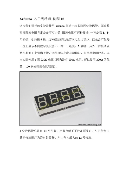
Arduino 入门到精通例程16这次我们进行的实验是使用arduino驱动一块共阳四位数码管。
驱动数码管限流电阻肯定是必不可少的,限流电阻有两种接法,一种是在d1-d4阳极接,总共接4颗。
这种接法好处是需求电阻比较少,但是会产生每一位上显示不同数字亮度会不一样,1最亮,8最暗。
另外一种接法就是在其他8个引脚上接,这种接法亮度显示均匀,但是用电阻较多。
本次实验使用8颗220Ω电阻(因为没有100Ω电阻,所以使用220Ω的代替,100欧姆亮度会比较高)。
4位数码管总共有12个引脚,小数点朝下正放在面前时,左下角为1,其他管脚顺序为逆时针旋转。
左上角为最大的12号管脚。
下图为数码管的说明手册下面是硬件连接图ARDUINO CODECOPY1.//设置阴极接口2.int a = 1;3.int b = 2;4.int c = 3;5.int d = 4;6.int e = 5;7.int f = 6;8.int g = 7;9.int p = 8;10.//设置阳极接口11.int d4 = 9;12.int d3 = 10;13.int d2 = 11;14.int d1 = 12;15.//设置变量16.long n = 0;17.int x = 100;18.int del = 55; //此处数值对时钟进行微调19.20.void setup()21.{22.pinMode(d1, OUTPUT);23.pinMode(d2, OUTPUT);24.pinMode(d3, OUTPUT);25.pinMode(d4, OUTPUT);26.pinMode(a, OUTPUT);27.pinMode(b, OUTPUT);28.pinMode(c, OUTPUT);29.pinMode(d, OUTPUT);30.pinMode(e, OUTPUT);31.pinMode(f, OUTPUT);32.pinMode(g, OUTPUT);33.pinMode(p, OUTPUT);34.}35.36.void loop()37.{38. clearLEDs();39. pickDigit(1);40. pickNumber((n/x/1000)%10);41.delayMicroseconds(del);42.43. clearLEDs();44. pickDigit(2);45. pickNumber((n/x/100)%10);46.delayMicroseconds(del);47.48. clearLEDs();49. pickDigit(3);50. dispDec(3);51. pickNumber((n/x/10)%10);52.delayMicroseconds(del);53.54. clearLEDs();55. pickDigit(4);56. pickNumber(n/x%10);57.delayMicroseconds(del);58.59. n++;60.61.if(digitalRead(13) == HIGH)62.{63. n = 0;64.}65.}66.67.void pickDigit(int x)//定义pickDigit(x),其作用是开启dx端口68.{69.digitalWrite(d1, LOW);70.digitalWrite(d2, LOW);71.digitalWrite(d3, LOW);72.digitalWrite(d4, LOW);73.74.switch(x)75.{76.case1:77.digitalWrite(d1, HIGH);78.break;79.case2:80.digitalWrite(d2, HIGH);81.break;82.case3:83.digitalWrite(d3, HIGH);84.break;85.default:86.digitalWrite(d4, HIGH);87.break;88.}89.}90.91.void pickNumber(int x)//定义pickNumber(x),其作用是显示数字x92.{93.switch(x)94.{95.default:96. zero();97.break;98.case1:99. one();100.break;101.case2:102. two();103.break;104.case3:105. three();106.break;107.case4:108. four();109.break;110.case5:111. five();112.break;113.case6:114. six();115.break;116.case7:117. seven();118.break;119.case8:120. eight();121.break;122.case9:123. nine();124.break;125.}126.}127.128.void dispDec(int x)//设定开启小数点129.{130.digitalWrite(p, LOW);131.}132.133.void clearLEDs()//清屏134.{135.digitalWrite(a, HIGH);136.digitalWrite(b, HIGH);137.digitalWrite(c, HIGH);138.digitalWrite(d, HIGH);139.digitalWrite(e, HIGH);140.digitalWrite(f, HIGH);141.digitalWrite(g, HIGH);142.digitalWrite(p, HIGH);143.}144.145.void zero()//定义数字0时阴极那些管脚开关146.{147.digitalWrite(a, LOW);148.digitalWrite(b, LOW);149.digitalWrite(c, LOW);150.digitalWrite(d, LOW);151.digitalWrite(e, LOW);152.digitalWrite(f, LOW);153.digitalWrite(g, HIGH);154.}155.156.void one()//定义数字1时阴极那些管脚开关157.{158.digitalWrite(a, HIGH);159.digitalWrite(b, LOW);160.digitalWrite(c, LOW);161.digitalWrite(d, HIGH);162.digitalWrite(e, HIGH);164.digitalWrite(g, HIGH);165.}166.167.void two()//定义数字2时阴极那些管脚开关168.{169.digitalWrite(a, LOW);170.digitalWrite(b, LOW);171.digitalWrite(c, HIGH);172.digitalWrite(d, LOW);173.digitalWrite(e, LOW);174.digitalWrite(f, HIGH);175.digitalWrite(g, LOW);176.}177.178.void three()//定义数字3时阴极那些管脚开关179.{180.digitalWrite(a, LOW);181.digitalWrite(b, LOW);182.digitalWrite(c, LOW);183.digitalWrite(d, LOW);184.digitalWrite(e, HIGH);185.digitalWrite(f, HIGH);186.digitalWrite(g, LOW);187.}188.189.void four()//定义数字4时阴极那些管脚开关190.{191.digitalWrite(a, HIGH);192.digitalWrite(b, LOW);193.digitalWrite(c, LOW);194.digitalWrite(d, HIGH);195.digitalWrite(e, HIGH);196.digitalWrite(f, LOW);197.digitalWrite(g, LOW);198.}199.200.void five()//定义数字5时阴极那些管脚开关201.{202.digitalWrite(a, LOW);204.digitalWrite(c, LOW);205.digitalWrite(d, LOW);206.digitalWrite(e, HIGH);207.digitalWrite(f, LOW);208.digitalWrite(g, LOW);209.}210.211.void six()//定义数字6时阴极那些管脚开关212.{213.digitalWrite(a, LOW);214.digitalWrite(b, HIGH);215.digitalWrite(c, LOW);216.digitalWrite(d, LOW);217.digitalWrite(e, LOW);218.digitalWrite(f, LOW);219.digitalWrite(g, LOW);220.}221.222.void seven()//定义数字7时阴极那些管脚开关223.{224.digitalWrite(a, LOW);225.digitalWrite(b, LOW);226.digitalWrite(c, LOW);227.digitalWrite(d, HIGH);228.digitalWrite(e, HIGH);229.digitalWrite(f, HIGH);230.digitalWrite(g, HIGH);231.}232.233.void eight()//定义数字8时阴极那些管脚开关234.{235.digitalWrite(a, LOW);236.digitalWrite(b, LOW);237.digitalWrite(c, LOW);238.digitalWrite(d, LOW);239.digitalWrite(e, LOW);240.digitalWrite(f, LOW);241.digitalWrite(g, LOW);242.}243.244.void nine()//定义数字9时阴极那些管脚开关245.{246.digitalWrite(a, LOW);247.digitalWrite(b, LOW);248.digitalWrite(c, LOW);249.digitalWrite(d, LOW);250.digitalWrite(e, HIGH);251.digitalWrite(f, LOW);252.digitalWrite(g, LOW);253.}把下面代码复制下载到控制板中,看看效果。
玩转ARDUINO
玩转ARDUINO}pulse width modulation(PWM)脉冲调宽// Variables will change:int ledState = LOW;// ledState used to set the LED long previousMillis = 0;// will store last time LED was updated// the follow variables is a long because the time, measured in miliseconds,// will quickly become a bigger number than can be stored in an int. long interval = 1000;// interval(间隔)at which to blink (milliseconds)void setup() {// set the digital pin as output:pinMode(ledPin, OUTPUT);}void loop(){// here is where you'd put code that needs to be running all the time.// check to see if it's time to blink the LED; that is, if the// difference between the current time and last time you blinked// the LED is bigger than the interval at which you want to// blink the LED.unsigned long currentMillis = millis();if(currentMillis - previousMillis > interval) {// save the last time you blinked the LEDpreviousMillis = currentMillis;// if the LED is off turn it on and vice-versa:if (ledState == LOW)ledState = HIGH;elseledState = LOW;// set the LED with the ledState of the variable:digitalWrite(ledPin, ledState);}}int ledState = HIGH;// the current state of the output pinint buttonState; // the current reading from the input pin int lastButtonState = LOW; // the previous reading from the input pin// the following variables are long's because the time, measured in miliseconds,// will quickly become a bigger number than can be stored in an int. long lastDebounceTime = 0;// the last time the output pin was toggledlong debounceDelay = 50; // the debounce time; increase if the output flickersvoid setup() {pinMode(buttonPin, INPUT);pinMode(ledPin, OUTPUT);// set initial LED statedigitalWrite(ledPin, ledState);}void loop() {// read the state of the switch into a local variable:int reading = digitalRead(buttonPin);// check to see if you just pressed the button// (i.e. the input went from LOW to HIGH), and you've waited// long enough since the last press to ignore any noise:// If the switch changed, due to noise or pressing:if (reading != lastButtonState) {// reset the debouncing timerlastDebounceTime = millis();}if ((millis() - lastDebounceTime) > debounceDelay) {// whatever the reading is at, it's been there for longer// than the debounce delay, so take it as the actual current state:// if the button state has changed:if (reading != buttonState) {buttonState = reading;// only toggle the LED if the new button state is HIGH// Variables will change:int buttonPushCounter = 0;// counter for the number of button pressesint buttonState = 0; // current state of the buttonint lastButtonState = 0;// previous state of the buttonvoid setup() {// initialize the button pin as a input:pinMode(buttonPin, INPUT);// initialize the LED as an output:pinMode(ledPin, OUTPUT);// initialize serial communication:Serial.begin(9600);}void loop() {// read the pushbutton input pin:buttonState = digitalRead(buttonPin);// compare the buttonState to its previous stateif (buttonState != lastButtonState) {// if the state has changed, increment the counterif (buttonState == HIGH) {// if the current state is HIGH then the button// wend from off to on:buttonPushCounter++;Serial.println("on");Serial.print("number of button pushes: ");Serial.println(buttonPushCounter);}else {// if the current state is LOW then the button// wend from on to off:Serial.println("off");}}// save the current state as the last state,//for next time through the looplastButtonState = buttonState;// turns on the LED every four button pushes by// checking the modulo of the button push counter.// the modulo function gives you the remainder of// the division of two numbers:if (buttonPushCounter % 4 == 0) {Initially, you set the minimum high and listen for anything lower, saving it as the new minimum. Likewise, you set the maximum low and listen for anything higher as the new maximum.The circuit:* Analog sensor (potentiometer will do) attached to analog input 0* LED attached from digital pin 9 to ground*/// These constants won't change:const int sensorPin = A0; // pin that the sensor is attached to const int ledPin = 9; // pin that the LED is attached to// variables:int sensorValue = 0; // the sensor valueint sensorMin = 1023; // minimum sensor valueint sensorMax = 0; // maximum sensor valuevoid setup() {// turn on LED to signal the start of the calibration period:pinMode(13, OUTPUT);digitalWrite(13, HIGH);// calibrate during the first five secondswhile (millis() < 5000) {sensorValue = analogRead(sensorPin);// record the maximum sensor valueif (sensorValue > sensorMax) {sensorMax = sensorValue;}// record the minimum sensor valueif (sensorValue < sensorMin) {sensorMin = sensorValue;}}// signal the end of the calibration perioddigitalWrite(13, LOW);}void loop() {// read the sensor:sensorValue = analogRead(sensorPin);// apply the calibration to the sensor readingsensorValue = map(sensorValue, sensorMin, sensorMax, 0, 255);This method can be used to control any series of digital outputs that depends on an analog input.The circuit:* LEDs from pins 2 through 11 to ground*/// these constants won't change:const int analogPin = A0;// the pin that the potentiometer is attached toconst int ledCount = 10; // the number of LEDs in the bar graphint ledPins[] = {2, 3, 4, 5, 6, 7,8,9,10,11 }; // an array of pin numbers to which LEDs are attachedvoid setup() {// loop over the pin array and set them all to output:for (int thisLed = 0; thisLed < ledCount; thisLed++) {pinMode(ledPins[thisLed], OUTPUT);}}void loop() {// read the potentiometer:int sensorReading = analogRead(analogPin);// map the result to a range from 0 to the number of LEDs:int ledLevel = map(sensorReading, 0, 1023, 0, ledCount);// loop over the LED array:for (int thisLed = 0; thisLed < ledCount; thisLed++) {// if the array element's index is less than ledLevel,// turn the pin for this element on:if (thisLed < ledLevel) {digitalWrite(ledPins[thisLed], HIGH);}// turn off all pins higher than the ledLevel:else {digitalWrite(ledPins[thisLed], LOW);}}}// cursor position:int x = 5;int y = 5;void setup() {// initialize the I/O pins as outputs// iterate over the pins:for (int thisPin = 0; thisPin < 8; thisPin++) {// initialize the output pins:pinMode(col[thisPin], OUTPUT);pinMode(row[thisPin], OUTPUT);// take the col pins (i.e. the cathodes) high to ensure that // the LEDS are off:digitalWrite(col[thisPin], HIGH);}// initialize the pixel matrix:for (int x = 0; x < 8; x++) {for (int y = 0; y < 8; y++) {pixels[x][y] = HIGH;}}}void loop() {// read input:readSensors();// draw the screen:refreshScreen();}void readSensors() {// turn off the last position:pixels[x][y] = HIGH;// read the sensors for X and Y values:x = 7 - map(analogRead(A0), 0, 1023, 0, 7);y = map(analogRead(A1), 0, 1023, 0, 7);// set the new pixel position low so that the LED will turn on // in the next screen refresh:pixels[x][y] = LOW;}HD44780 driver. There are many of them out there, and you can usually tell them by the 16-pin interface.This sketch demonstrates how to use leftToRight() and rightT oLeft() to move the cursor.The circuit:* LCD RS pin to digital pin 12* LCD Enable pin to digital pin 11* LCD D4 pin to digital pin 5* LCD D5 pin to digital pin 4* LCD D6 pin to digital pin 3* LCD D7 pin to digital pin 2* LCD R/W pin to ground* 10K resistor:* ends to +5V and ground* wiper to LCD VO pin (pin 3)*/// include the library code:#include <LiquidCrystal.h>// initialize the library with the numbers of the interface pins LiquidCrystal lcd(12, 11, 5, 4, 3, 2);int thisChar = 'a';void setup() {// set up the LCD's number of columns and rows:lcd.begin(16, 2);// turn on the cursor:lcd.cursor();}void loop() {// reverse directions at 'm':if (thisChar == 'm') {// go right for the next letterlcd.rightToLeft();}// reverse again at 's':if (thisChar == 's') {// go left for the next letterlcd.leftT oRight();* ends to +5V and ground* wiper to LCD VO pin (pin 3)*/// include the library code:#include <LiquidCrystal.h>// initialize the library with the numbers of the interface pins LiquidCrystal lcd(12, 11, 5, 4, 3, 2);void setup() {// set up the LCD's number of columns and rows:lcd.begin(16, 2);// Print a message to the LCD.lcd.print("hello, world!");delay(1000);}void loop() {// scroll 13 positions (string length) to the left// to move it offscreen left:for (int positionCounter = 0; positionCounter < 13; positionCounter++) { // scroll one position left:lcd.scrollDisplayLeft();// wait a bit:delay(150);}// scroll 29 positions (string length + display length) to the right// to move it offscreen right:for (int positionCounter = 0; positionCounter < 29; positionCounter++) { // scroll one position right:lcd.scrollDisplayRight();// wait a bit:delay(150);}// scroll 16 positions (display length + string length) to the left// to move it back to center:for (int positionCounter = 0; positionCounter < 16; positionCounter++) { // scroll one position left:lcd.scrollDisplayLeft();// wait a bit:The circuit:* LCD RS pin to digital pin 12* LCD Enable pin to digital pin 11* LCD D4 pin to digital pin 5* LCD D5 pin to digital pin 4* LCD D6 pin to digital pin 3* LCD D7 pin to digital pin 2* LCD R/W pin to ground* 10K resistor:* ends to +5V and ground* wiper to LCD VO pin (pin 3)*/// include the library code:#include <LiquidCrystal.h>// these constants won't change. But you can change the size of // your LCD using them:const int numRows = 2;const int numCols = 16;// initialize the library with the numbers of the interface pins LiquidCrystal lcd(12, 11, 5, 4, 3, 2);void setup() {// set up the LCD's number of columns and rows:lcd.begin(numCols,numRows);}void loop() {// loop from ASCII 'a' to ASCII 'z':for (int thisLetter = 'a'; thisLetter <= 'z'; thisLetter++) {// loop over the columns:for (int thisCol = 0; thisCol < numRows; thisCol++) {// loop over the rows:for (int thisRow = 0; thisRow < numCols; thisRow++) {// set the cursor position:lcd.setCursor(thisRow,thisCol);// print the letter:lcd.write(thisLetter);delay(200);}}}}代码//IR receive demo v1.0#include <IRSendRev.h>//#include <IRSendRevInt.h>#define IR_OUT_PIN 2//The OUT pin of the Infrared Receiver is connected to D2 of//Arduino/Catduinovoid setup(){Serial.begin(38400);IR.Init(IR_OUT_PIN);Serial.println("init over");}unsigned char dta[20];void loop(){if(IR.IsDta()){// IR.Recv(dta);int length= IR.Recv(dta);for (int i =0;i<length;i++){Serial.print(dta[i]);Serial.print("\t");}Serial.println();// Very Important:// the received data is comprised of the trsmission parameters ,// please refer to// the sendTest.ino in the library ;}}// ir send test// Infrared Emitter connect to D3#include <IRSendRev.h>const int Button = 7;const int irFreq = 38;unsigned char dtaSend[] = {9, 90, 91, 11, 31, 4, 1, 2, 3, 4};void setup(){pinMode(Button, INPUT);}void loop(){if(digitalRead(Button)) // button press{IR.Send(dtaSend, irFreq); // send dataconst int pinB = 10;int originX = 0;int originY = 0;int color_r = 0;int color_g = 0;int color_b = 0;// get value of analogint getAnalog(int pin){int sum = 0;for(int i=0; i<32; i++){sum += analogRead(pin);}return sum >> 5;}void makeRGB(){int x = getAnalog(pinX) - originX;int y = getAnalog(pinY) - originY;if(x < 0){x = -x;color_r = map(x, 0, 280, 255, 0);}else if(x > 0){color_g = map(x, 0, 280, 255, 0);}else{color_r = 255;color_g = 255;}y = abs(y);color_b = map(y, 0, 280, 255, 0);analogWrite(pinR, color_r);analogWrite(pinG, color_g);analogWrite(pinB, color_b);}void setup(){originX = getAnalog(pinX);originY = getAnalog(pinY);pinMode(pinR, OUTPUT);pinMode(pinG, OUTPUT);pinMode(pinB, OUTPUT);。
ARDUINO教程第四讲

2、红外寻线传感器组件
由三个寻线传感器组成。背面L、C、R分别 为左中右的信号输出。
int L=7; //左边传感器接第7脚 int C=8; //中间传感器接第8脚 int R=9; //右边传感器接第9脚 void setup() {pinMode(L,INPUT); //均设置为输入 pinMode(C,INPUT); pinMode(R,INPUT); Serial.begin(9600); //串口波特率为9600 } void loop() { if(digitalRead(L)==HIGH) Serial.print(“Left is White |”); //若测到高电平则输出白色 else Serial.print(“Left is Black |”); //否则输出黑色 if(digitalRead(C)==HIGH) Serial.print("Center is White |"); else Serial.print("Center is Black |"); if(digitalRead(R)==HIGH) Serial.println("Right is White"); else Serial.println("Right is Black"); delay(200); //延时200MS方便观察效果 }
detch(pin); 该函数用于释放舵机引脚,可以作为其 他用途。
read(pin); 该函数用于返回当前舵机的角度,范围 0~180度
readMicrosends(pin); 该函数用于返回当前舵机的脉冲值,单 位us,范围在最大脉冲宽度和最小脉冲 宽度之间。
Arduino手把手系列教程

Arduino手把手系列教程Arduino手把手入门系列教程1――什么是Arduino/Arduino是什么Arduino是一块简单、方便使用的通用GPIO接口板,并可以通过USB接口和电脑通信。
作为一块通用IO接口板,Arduino提供丰富的资源,包括:13个数字IO口(DIO数字输入输出口);6个PWM输出(AOUT可做模拟输出口使用);5个模拟输入口(AIN模拟输入)。
Arduino开发使用java开发的编程环境,使用类c语言编程,并提供丰富的库函数。
Arduino可以和下列软件结合创作丰富多彩的互动作品:Flash,Processing,Max/MSP,VVVV。
等。
Arduino也可以用独立的方式运作,开发电子互动作品,例如:开关控制Switch、传感器sensors输入、LED等显示器件、各种马达或其它输出装置。
下面是Arduino的硬件实物图片:Arduino实物图Arduino手把手入门系列教程2――Arduino可以做什么目前计算机的输入和输出设备,大家常见的、也是大家做熟悉的就是:键盘(输入)、鼠标(输入)、麦克(输入)和音响(输出)、显示器(输出);对于一些玩游戏的朋友可能还包括游戏杆(输入),做音乐的可能还会接触到MIDI(输入)。
上述设备都很专业,功能也非常专一。
你没办法让键盘给你唱歌,同样,你也没办法让音响替你输入文本。
Arduino更像是一种半成品,它提供通用的输入输出接口。
你可以通过编程,把Arduino加工成你需要的输入输出设备。
你可以把Arduino做成键盘、鼠标、麦克等输入设备;你也可以把Arduino做成音响、显示器等输出设备。
最重要的是,你可以把Arduino做成任何你希望的互动工具(输入和输出)。
如果你愿意,或者你需要,你完全可做使用Arduino开发出一个会唱歌的键盘或者一个让你的音响替你打字。
(夸张的说法)总之,Arduino是什么,是根据你的需求来确定的。
(完整word版)ARDUINO入门及其简单实验(7例)

ARDUINO入门及其简单实验(7例) (2)1. Arduino硬件开发平台简介 (2)1.1 Arduino的主要特色 (3)1.2 Arduino的硬件接口功能描述 (3)1.3 Arduino的技术性能参数 (4)1.4 电路原理图 (4)2. Arduino软件开发平台简介 (5)2.1 菜单栏 (6)2.2 工具栏 (6)2.3 Arduino 语言简介 (7)3. Arduino开发实例中所用部分器件 (9)1. LED简介 (9)2. 光敏电阻简介 (10)3. 直流电机简介 (10)4. 电位器简介 (10)4. Arduino平台应用开发实例 (11)4.1【实作项目一】利用LED作光敏电阻采样实验 (11)4.2【实作项目二】利用PWM信号控制LED亮度 (13)4.3【实作项目三】单键控制一只LED的亮灭 (15)4.4【实作项目四】利用PWM控制直流电机转速 (17)4.5【实作项目五】利用电位器手控LED亮度 (20)4.6【实作项目六】控制LED明暗交替 (22)4.7【实作项目七】利用光敏电阻控制LED的亮灭 (24)ARDUINO入门及其简单实验(7例)1. Arduino硬件开发平台简介Arduino硬件是一块带有USB的I/O接口板(其中包括13条数字I/O引脚,6通道模拟输出,6通道模拟输入),并且具有类似于Java、C语言的集成开发环境。
Arduino既可以扩展一些外接的电子元器件,例如开关、传感器、LED、直流马达、步进马达或其他输入、输出装置;Arduino也可以独立运行,成为一个可以跟交互软件沟通的接口装置,例如:Flash、Processing、Max/MSP、VVVV或其他互动软件。
Arduino开发环境IDE全部开放源代码,可以供大家免费下载、利用,还可以开发出更多激发人们制作欲望的互动作品。
如图1和图2所示,分别为Arduino硬件平台的实物图和电路布局图。
Arduino教程

Arduino教程Arduino LWZ 教程V1.0目录一、Arduino编程语言 (4)1、数据类型: (4)2、常量: (4)3、基本语句: (4)(1)if语句 (4)(2)if...else...语句 (5)(3)for语句 (5)(4)break和continue (6)(5)switch case语句 (6)(6)while语句和do...while语句 (7)(7)return语句 (8)(8)运算符 (8)(9)函数 (8)4、结构函数: (8)5、功能函数: (9)(1)数字I/O函数 (9)(2)模拟I/O函数 (9)(3)时间函数 (9)(4)数学函数 (10)(5)数据类型转换函数 (10)(6)三角函数 (10)(7)随机数函数 (10)(8)外部中断函数 (11)(9)中断使能函数 (11)(10)串口收发函数 (11)6、官方库文件: (11)二、Sabertooth电机驱动模块应用实例 (13)1、工作模式 (13)(1)Mode1: Analog Input (13)(2)Mode2:R/C Input (14)(3)Mode3:Simplified serial (14)(4)Mode4:Packetized serial (15)2、应用实例 (17)(1)硬件连接 (17)(2)小车停止函数 (18)(3)小车前进函数 (19)(4)小车后退函数 (19)(5)小车右转函数 (20)(6)小车左转函数 (21)(7)电子积木编程思路 (22)(8)PC软件的编程思路 (25)(1)硬件连接 (25)(2)电子积木运动和初始化函数 (25)(3)电子积木编程思路 (26)4、通过无线模块控制小车 (28)(1)无线通信模块 (28)(2)硬件连接 (28)(3)电子积木编程思路 (28)5、下载程序串口COM和无线数模串口COM2同时控制小车 (30)(1)硬件连接 (31)(2)电子积木编程思路 (31)三、TN901_TEST非接触测温模块应用实例 (34)1、TN901工作原理 (34)2、应用实例 (36)(1)硬件连接 (36)(2)读取温度函数 (36)(3)初始化函数 (38)(4)电子积木编程思路 (38)3、多个TN模块的应用实例 (39)(1)硬件连接 (39)(2)初始化函数 (39)(3)电子积木编程思想:共享函数 (40)(4)电子积木编程思路:独立函数 (42)四、气体传感器模块应用实例 (46)1、应用实例 (46)(1)硬件连接 (46)(2)电子积木编程思路 (46)2、多个气体传感器的应用实例 (47)(1)硬件连接 (47)(2)电子积木编程思路 (47)五、火焰传感器模块应用实例 (48)1、应用实例 (48)(1)硬件连接 (48)(2)电子积木编程思路 (49)2、多个火焰传感器的应用实例 (49)(1)硬件连接 (49)(2)电子积木编程思路 (50)六、DF-miniLTV3寻线模块应用实例 (50)1、DF-miniLTV3寻线工作原理 (50)2、DF-miniLTV3寻线在单黑线的应用实例 (51)(1)硬件连接 (52)(2)Sabertooth模块函数 (52)(3)初始化函数 (52)(4)电子积木编程思路 (52)(1)硬件连接 (54)(2)电子积木编程思路 (54)(2)PC软件的编程思路 (56)七、舵机模块应用实例 (56)1、舵机工作原理 (56)2、应用实例 (57)(1)硬件连接 (57)(2)电子积木编程思路 (57)3、非库形式的应用实例 (59)(1)硬件连接 (59)(2)双舵机驱动函数 (59)八、综合实例 (63)1、驱动2台舵机和电机的应用实例 (63)(1)硬件连接 (63)(2)电子积木编程思路 (64)2、测3个测温度、驱动电机的应用实例 (64)(1)硬件连接 (64)(2)电子积木编程思路 (64)3、测3个测温度、驱动2台舵机和电机的应用实例 (65)(1)硬件连接 (65)(2)电子积木编程思路 (65)4、测2个气体、2个火焰、3个测温度、驱动2台舵机和电机的应用实例 (65)(1)硬件连接 (65)(2)电子积木编程思路 (65)5、寻线、测2个气体、2个火焰、3个测温度、驱动2台舵机和电机的应用实例 (66)(1)硬件连接 (66)(2)电子积木编程思路 (66)一、Arduino编程语言Arduino语言是建立在C/C++基础上的。
Arduino 入门到精通 例程6-抢答器
Arduino 入门到精通例程7抢答器设计实验完成上面的实验以后相信已经有很多朋友可以独立完成这个实验了,本实验就是将上面的按键控制小灯的实验扩展成3 个按键对应3 个小灯,占用6 个数字I/O 接口。
电路连接图原理这里就不多说了同上面实验,下面附上参考原理图和实物连接图。
参考源程序如下:int redled=8; //红色LED 输出int yellowled=7; //黄色LED输出int greenled=6; //绿色LED输出int redpin=5; //红色按键引脚int yellowpin=4; //黄色按键引脚int greenpin=3; //绿色按键引脚int restpin=2; //复位按键引脚定义int red;int yellow;int green;void setup(){pinMode(redled,OUTPUT);pinMode(yellowled,OUTPUT);pinMode(greenled,OUTPUT);pinMode(redpin,INPUT);pinMode(yellowpin,INPUT);pinMode(greenpin,INPUT);}void loop() //按键循环扫描。
{red=digitalRead(redpin);yellow=digitalRead(yellowpin);green=digitalRead(greenpin);if(red==LOW)RED_YES();if(yellow==LOW)YELLOW_YES();if(green==LOW)GREEN_YES();}void RED_YES()//一直执行红灯亮,直到复位键按下,结束循环{while(digitalRead(restpin)==1){digitalWrite(redled,HIGH);digitalWrite(greenled,LOW);digitalWrite(yellowled,LOW);}clear_led();}void YELLOW_YES()//一直执行黄灯亮,直到复位键按下,结束循环{while(digitalRead(restpin)==1){digitalWrite(redled,LOW);digitalWrite(greenled,LOW);digitalWrite(yellowled,HIGH);}clear_led();}void GREEN_YES()//一直执行绿灯亮,直到复位键按下,结束循环{while(digitalRead(restpin)==1){digitalWrite(redled,LOW);digitalWrite(greenled,HIGH);digitalWrite(yellowled,LOW);}clear_led();}void clear_led()//清除LED{digitalWrite(redled,LOW);digitalWrite(greenled,LOW);digitalWrite(yellowled,LOW);}实验现象,都说了是抢答器,肯定是谁先按下,就亮谁的灯啦!然后按下REST按键后,复位。
arduino教程-----第二课 Arduino 开发板的说明
Arduino 板的说明在本章中,我们将了解Arduino板上的不同组件。
将学习Arduino UNO板,因为它是Arduino板系列中最受欢迎的。
此外,它是开始使用电子和编码的最佳板。
有些板看起来与下面给出的有些不同,但多数Arduino中的这些组件大部分是共同的。
电源Arduino线连接到电源(桶插座)Arduino稳压器稳压器的功能是控制提供给元件使用的直流电压。
晶体振荡器晶振帮助过使用晶体振荡器。
告诉我们,频率是Arduino你可以重置你的过两种方式重置次,你可以将外部复位按钮连接到标有引脚(3.3V5V使用常工作。
GND用于将电路接地。
VVin板供电。
模拟引脚Arduino UNO传感器(如湿度传感器或温度传感器)读取信号,并将其转换为可由微处理器读取的数字值。
微控制器每个大脑。
通常是道你的板上有什么多详细信息,请参阅数据表。
ICSP大多数情况下,VCC设接口),可以被认为是输出的“扩展”。
实际上,你是将输出设备从属到电源当你将已正确通电。
如果这个指示灯不亮,那么连接就出现了问题。
TX在你的板上,你会发现两个标签:现在引脚负责串行通信。
其次,LED收过程中闪烁。
数字Arduino UNO宽调制)输出),这些引脚可配置为数字输入引脚,用于读取逻辑值(等。
标有“AREFAREF作为模拟输入引脚的上限。
Arduino 教程--第四十四课 Arduino 音调库
第四十四课Arduino 音调库
在本章中,我们将使用Arduino音调库。
它只是一个Arduino库,可以在任意Arduino 引脚上产生指定频率(50%占空比)的方波。
持续时间可以有选择的指定,否则方波会一直持续到stop()函数被调用。
该引脚可以连接到压电蜂鸣器或扬声器播放音调。
警告 - 不要将引脚直接连接到任何音频输入。
电压远远高于标准线路电压,并可能损坏声卡输入等。
你可以使用分压器来降低电压。
必需的组件
你将需要以下组件:
• 1 × 8欧姆扬声器
• 1 × 1k电阻
• 1 × Arduino UNO 板
程序
按照电路图进行连接,如下图所示。
草图
在计算机上打开Arduino IDE软件。
使用Arduino语言进行编码控制你的电路。
通过单击“New”打开一个新的草图文件。
要制作pitches.h文件,请单击串口监视器图标正下方的按钮,然后选择“New Tab”,或使用Ctrl+Shift+N。
然后粘贴以下代码:
将上面给出的代码保存为 pitches.h Arduino代码
代码说明
代码使用一个额外的文件,pitches.h。
此文件包含典型音符的所有音高值。
例如,NOTE_C4是中央C。
NOTE_FS4是F#,等等。
这个注释表最初是由Brett Hagman编写的,tone()命令是基于它工作的。
当你想制作音符时会发现它很有用。
结果
你会听到保存在pitches.h文件中的音符。
Arduino教程
Arduino教程一: 数字输出Arduino, 教程11 Comments »Arduino的数字I/O被分成两个部分,其中每个部分都包含有6个可用的I/O管脚,即管脚2到管脚7和管脚8到管脚13。
除了管脚13上接了一个1K的电阻之外,其他各个管脚都直接连接到ATmega上。
我们可以利用一个6位的数字跑马灯,来对Arduino数字I/O 的输出功能进行验证,以下是相应的原理图:电路中在每个I/O管脚上加的那个1K电阻被称为限流电阻,由于发光二极管在电路中没有等效电阻值,使用限流电阻可以使元件上通过的电流不至于过大,能够起到保护的作用。
该工程对应的代码为:int BASE = 2;int NUM = 6;int index = 0;void setup(){for (int i = BASE; i < BASE + NUM; i ++){pinMode(i, OUTPUT);}}void loop(){for (int i = BASE; i < BASE + NUM; i ++) {digitalWrite(i, LOW);}digitalWrite(BASE + index, HIGH);index = (index + 1) % NUM;delay(100);}下载并运行该工程,连接在Arduino数字I/O管脚2到管脚7上的发光二极管会依次点亮0.1秒,然后再熄灭:这个实验可以用来验证数字I/O输出的正确性。
Arduino上一共有十二个数字I/O管脚,我们可以用同样的办法验证其他六个管脚的正确性,而这只需要对上述工程的第一行做相应的修改就可以了:int BASE = 8;SEP01Arduino教程二: 数字输入Arduino, 教程3 Comments »在数字电路中开关(switch)是一种基本的输入形式,它的作用是保持电路的连接或者断开。
Arduino从数字I/O管脚上只能读出高电平(5V)或者低电平(0V),因此我们首先面临到的一个问题就是如何将开关的开/断状态转变成Arduino能够读取的高/低电平。
- 1、下载文档前请自行甄别文档内容的完整性,平台不提供额外的编辑、内容补充、找答案等附加服务。
- 2、"仅部分预览"的文档,不可在线预览部分如存在完整性等问题,可反馈申请退款(可完整预览的文档不适用该条件!)。
- 3、如文档侵犯您的权益,请联系客服反馈,我们会尽快为您处理(人工客服工作时间:9:00-18:30)。
触摸传感器
倾斜传感器
人体运动 红外热释传感器
反射型红外开关 50cm~100cm
反射型红外开关 10cm
反射型红外开关 2cm
对射型 红外开关 8米
继电器模块
动手
• 通过按钮模拟来控制LED灯的亮灭
面包板使用方法介绍
动手
• 用面包板完成LED模块的电路连接
LED基本电路
电阻
LED
– Serial.print(val), Serial.println(val)
• 输出ASCII码(后者多一个回车换行)
– Serial.print(val, format) , Serial.println(val, format)
• 按指定格式输出(后者多一个回车换行)
Serial.print(val) 实例
玩转Arduino合集
Arduino是什么?
• Arduino硬件介绍 • Arduino编程环境介绍
Arduino的安装
• Arduino IDE的安装 • USB驱动的安装
Arduino程序结构:setup()
上电后setup()函数执行一次
4
Arduino程序结构:loop()
loop()函数一直循环运行
动手
• 实验各种模拟传感器 • 对RGB LED进行控制 • 分享
串口通信
• 串口通信(Serial Communication)是Arduino和计算机间 按位进行数据传输的一种最基本的方式。
• 使用3根线完成
– 地线,GND – 发送,Tx – 接收 ,Rx
• 主要参数
– 波特率:通信速度,表示每秒钟传送的位(bit)的个数 – 数据位 – 停止位 – 奇偶校验位
电源(正/负)
LED控制代码
动手
• 使用Arduino和传感器扩展板 • 使用Arduino的9,10,11三个引脚 • 使用三个LED和1K的电阻 • 通过程序进行控制 • 讨论
彩色LED
• 红/绿/蓝 三原色 • 根据公共端的不同有共阳/共阴两种
动手
• 更换RGB LED • 用Arduino程序混色 • 讨论
Arduino 串口
• USB转串口
– PC端:串口 – Arduino端:USB
• 串口引脚
– RX:Pin 0 – TX:Pin 1
• 串口数目
– Arduino MEGA和Arduino 2560:4个 – 其余:1个
• 串口初始化函数
– Serial.begin(speed)
• speed: 300, 1200, 2400, 4800, 9600, 14400, 19200, 28800, 38400, 57600, 115200
• 尝试输出更多格式的数据到计算机
– Serial.print(78) – Serial.print(1.23456) – Serial.print(byte(78)) – Serial.print('N') – Serial.print("Hello world.") – Serial.print(78, BYTE) – Serial.print(78, BIN) – Serial.print(78, DEC) – Serial.print(78, HEX) – Serial.print(1.23456, 2)
– 输出"Hello world."
Serial.print(val, format) 实例
• Serial.print(78, BYTE)
– 输出"N"
• Serial.print(78, BIN)
– 输出"1001110"
• Serial.print(78, OCT)
– 输出"116"
• Serial.print(78, DEC)
– 通常在 setup() 函数里调用
Arduino 串口输出
• 将数据从Arduino传输到PC
– TX 串口转USB PC端软件串口监视软件 – Arduino IDE自带串口监视软件 – 也可以用其它软件进行接收:Flash, Processing, Director, vvvv等
• 串口输出函数
– 3, 5, 6, 9, 10, 11
• value取值0-255
• PWM
– 实现模拟信号的数字化方法
动手
• Arduino控制LED淡入淡出效果
动手
• 实现全彩的混色
模拟输入
• 通常基于分压原理 • 电位器 • 电子积木
– 300度 旋转角度传感器
Arduino中的模拟输入
• analogRead(pin)
声音传感器
Sharp 红外距离传感器
• 30cm, 80cm, 150cm, 5.5m
三轴 加速度传感器
FlexiForce压力传感器
• 1 lb, 25 lb, 100 lb
FSR系列压力传感器
• 压力1-10kG • 尺寸和外形不同
弯曲传感器
• 单向,双向
拉伸 传感器
• 4 inch, 6 inch
– pin: 模拟输入引脚 A0, A1, A2, A3, A4, A5 – 返回值: 0-1024 (10位精度)
动手
• 通过读取电位器的值来控制LED灯的亮度
300度 旋转角度传感器
多圈 旋转角度传感器
60行程 滑动电位器 推子
游戏杆 控制杆 JoyStick
模拟温度传感器
光线传感器
– 输出"78"
• Serial.print(78, HEX)
– 输出"4E"
• Serial.print(1.23456, 0)
– 输出"1"
• Serial.print(1.23456, 2)
– 输出"1.23"
• Serial.print(1.23456, 4)
– 输出"1.2346"
动手Leabharlann 手• Serial.print(78)
– 输出"78"
• Serial.print(1.23456)
– 输出"1.23"
• Serial.print(byte(78))
– 输出“N” (N的ASCII码值为78))
• Serial.print('N')
– 输出"N"
• Serial.print("Hello world.")
模拟信号
• 模拟信号的值可以连续变化 • 9V电池就是一种模拟器件,因为它的输出电压并不精确地
等于9V,而是随时间发生变化,并可取任何实数值。 • 光照强度、温度、湿度等也都是模拟信号
Arduino中的模拟输出
• analogWrite(pin, value) • pin为Arduino上的PWM引脚
5
Arduino数字输入输出
6
Arduino程序下载
• HelloWorld程序
动手
• HelloWorld:点亮一个LED灯
Arduino与电子积木
• 什么是电子积木 • 电子积木如何与Arduino连接
– 传感器扩展板 – 连接线
数字型电子积木
通用按钮模块
小按钮模块
大按钮模块
磁力开关