动手玩转Arduino(精)
林锋教你一步一步玩机器人(arduino)-基础篇

林锋教你一步一步玩机器人(arduino)系列------基础篇----- 张林锋/文2012-5-22目录1. 闲话杂谈 (3)2. Arduino 介绍 (6)2.1 Arduino的概念 (6)2.2 Arduino的特点 (7)2.1 Arduino 的发音 (7)2.2 Arduino 的历史 (7)2.3 Arduino 的家族 (8)3. Arduino 在国内的发展 (9)3.1 简介 (9)3.2 国内玩家介绍 (10)说明写这系列文章主要目的是和读者一同分享下自己的学习过程,也希望能给读者带来一些帮助,文章部分内容剪裁网络文章,部分自己撰写。
文章内容用于爱好者之间学习,不得用于商业目的。
当然笔者才疏学浅,所书内容难免有缺点和漏洞,还请读者多多海涵,希望能和广大电子爱好者交流心得。
本人QQ:65198204邮箱:65198024@博客:/u/27758246901. 闲话杂谈下面这段话是我个人的杂谈,也非自传,只是觉得自己大学毕业也7年了,总想说点什么。
大家有兴趣的话可以当做茶余饭后之闲谈,也可以跳过直奔主题,呵呵。
说到电子这个东东,我还从小就和它结下了不解之缘。
我还是读小学,90年代,每次在回家的路上会经过一个电子厂,能捡到一些报废的电子管。
当时觉得这个东东长得很像宇宙飞船,(估计是受动画片的影响)。
图1 电子管大概记得小学4,5年级的时候,我就开始鼓弄DIY了,呵呵,大家估计要口水我了,那时候所谓的DIY当然不是什么很牛X的大制作了,看看大家还记得小时候喝过高乐高没有,如果有印象的就知道高乐高里面会送一个搅拌器。
图2 高乐高当时我就把搅拌器里的电机拿出来,用橡皮泥粘在小车上,把电机的轴上绑一个棒棒糖送的螺旋桨,引2根长点的导线到电机的正负极上,然后通2个我老爸相机上东芝的5号电池,利用风力推动小车走。
(现在这些小直流电机部分还保留在家里,老古董了,通电还能转,不过好大噪音,上点油,装个减速器还能用上Arduino小车哟!)后来就是玩小霸王(游戏机),初中就玩DOS系统,386电脑,红警,97版本仙剑奇侠传,高中就流行互联网了,什么传奇,CS,等等。
玩转ARDUINO
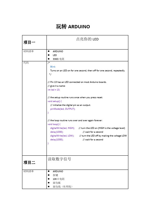
玩转ARDUINO}pulse width modulation(PWM)脉冲调宽// Variables will change:int ledState = LOW;// ledState used to set the LED long previousMillis = 0;// will store last time LED was updated// the follow variables is a long because the time, measured in miliseconds,// will quickly become a bigger number than can be stored in an int. long interval = 1000;// interval(间隔)at which to blink (milliseconds)void setup() {// set the digital pin as output:pinMode(ledPin, OUTPUT);}void loop(){// here is where you'd put code that needs to be running all the time.// check to see if it's time to blink the LED; that is, if the// difference between the current time and last time you blinked// the LED is bigger than the interval at which you want to// blink the LED.unsigned long currentMillis = millis();if(currentMillis - previousMillis > interval) {// save the last time you blinked the LEDpreviousMillis = currentMillis;// if the LED is off turn it on and vice-versa:if (ledState == LOW)ledState = HIGH;elseledState = LOW;// set the LED with the ledState of the variable:digitalWrite(ledPin, ledState);}}int ledState = HIGH;// the current state of the output pinint buttonState; // the current reading from the input pin int lastButtonState = LOW; // the previous reading from the input pin// the following variables are long's because the time, measured in miliseconds,// will quickly become a bigger number than can be stored in an int. long lastDebounceTime = 0;// the last time the output pin was toggledlong debounceDelay = 50; // the debounce time; increase if the output flickersvoid setup() {pinMode(buttonPin, INPUT);pinMode(ledPin, OUTPUT);// set initial LED statedigitalWrite(ledPin, ledState);}void loop() {// read the state of the switch into a local variable:int reading = digitalRead(buttonPin);// check to see if you just pressed the button// (i.e. the input went from LOW to HIGH), and you've waited// long enough since the last press to ignore any noise:// If the switch changed, due to noise or pressing:if (reading != lastButtonState) {// reset the debouncing timerlastDebounceTime = millis();}if ((millis() - lastDebounceTime) > debounceDelay) {// whatever the reading is at, it's been there for longer// than the debounce delay, so take it as the actual current state:// if the button state has changed:if (reading != buttonState) {buttonState = reading;// only toggle the LED if the new button state is HIGH// Variables will change:int buttonPushCounter = 0;// counter for the number of button pressesint buttonState = 0; // current state of the buttonint lastButtonState = 0;// previous state of the buttonvoid setup() {// initialize the button pin as a input:pinMode(buttonPin, INPUT);// initialize the LED as an output:pinMode(ledPin, OUTPUT);// initialize serial communication:Serial.begin(9600);}void loop() {// read the pushbutton input pin:buttonState = digitalRead(buttonPin);// compare the buttonState to its previous stateif (buttonState != lastButtonState) {// if the state has changed, increment the counterif (buttonState == HIGH) {// if the current state is HIGH then the button// wend from off to on:buttonPushCounter++;Serial.println("on");Serial.print("number of button pushes: ");Serial.println(buttonPushCounter);}else {// if the current state is LOW then the button// wend from on to off:Serial.println("off");}}// save the current state as the last state,//for next time through the looplastButtonState = buttonState;// turns on the LED every four button pushes by// checking the modulo of the button push counter.// the modulo function gives you the remainder of// the division of two numbers:if (buttonPushCounter % 4 == 0) {Initially, you set the minimum high and listen for anything lower, saving it as the new minimum. Likewise, you set the maximum low and listen for anything higher as the new maximum.The circuit:* Analog sensor (potentiometer will do) attached to analog input 0* LED attached from digital pin 9 to ground*/// These constants won't change:const int sensorPin = A0; // pin that the sensor is attached to const int ledPin = 9; // pin that the LED is attached to// variables:int sensorValue = 0; // the sensor valueint sensorMin = 1023; // minimum sensor valueint sensorMax = 0; // maximum sensor valuevoid setup() {// turn on LED to signal the start of the calibration period:pinMode(13, OUTPUT);digitalWrite(13, HIGH);// calibrate during the first five secondswhile (millis() < 5000) {sensorValue = analogRead(sensorPin);// record the maximum sensor valueif (sensorValue > sensorMax) {sensorMax = sensorValue;}// record the minimum sensor valueif (sensorValue < sensorMin) {sensorMin = sensorValue;}}// signal the end of the calibration perioddigitalWrite(13, LOW);}void loop() {// read the sensor:sensorValue = analogRead(sensorPin);// apply the calibration to the sensor readingsensorValue = map(sensorValue, sensorMin, sensorMax, 0, 255);This method can be used to control any series of digital outputs that depends on an analog input.The circuit:* LEDs from pins 2 through 11 to ground*/// these constants won't change:const int analogPin = A0;// the pin that the potentiometer is attached toconst int ledCount = 10; // the number of LEDs in the bar graphint ledPins[] = {2, 3, 4, 5, 6, 7,8,9,10,11 }; // an array of pin numbers to which LEDs are attachedvoid setup() {// loop over the pin array and set them all to output:for (int thisLed = 0; thisLed < ledCount; thisLed++) {pinMode(ledPins[thisLed], OUTPUT);}}void loop() {// read the potentiometer:int sensorReading = analogRead(analogPin);// map the result to a range from 0 to the number of LEDs:int ledLevel = map(sensorReading, 0, 1023, 0, ledCount);// loop over the LED array:for (int thisLed = 0; thisLed < ledCount; thisLed++) {// if the array element's index is less than ledLevel,// turn the pin for this element on:if (thisLed < ledLevel) {digitalWrite(ledPins[thisLed], HIGH);}// turn off all pins higher than the ledLevel:else {digitalWrite(ledPins[thisLed], LOW);}}}// cursor position:int x = 5;int y = 5;void setup() {// initialize the I/O pins as outputs// iterate over the pins:for (int thisPin = 0; thisPin < 8; thisPin++) {// initialize the output pins:pinMode(col[thisPin], OUTPUT);pinMode(row[thisPin], OUTPUT);// take the col pins (i.e. the cathodes) high to ensure that // the LEDS are off:digitalWrite(col[thisPin], HIGH);}// initialize the pixel matrix:for (int x = 0; x < 8; x++) {for (int y = 0; y < 8; y++) {pixels[x][y] = HIGH;}}}void loop() {// read input:readSensors();// draw the screen:refreshScreen();}void readSensors() {// turn off the last position:pixels[x][y] = HIGH;// read the sensors for X and Y values:x = 7 - map(analogRead(A0), 0, 1023, 0, 7);y = map(analogRead(A1), 0, 1023, 0, 7);// set the new pixel position low so that the LED will turn on // in the next screen refresh:pixels[x][y] = LOW;}HD44780 driver. There are many of them out there, and you can usually tell them by the 16-pin interface.This sketch demonstrates how to use leftToRight() and rightT oLeft() to move the cursor.The circuit:* LCD RS pin to digital pin 12* LCD Enable pin to digital pin 11* LCD D4 pin to digital pin 5* LCD D5 pin to digital pin 4* LCD D6 pin to digital pin 3* LCD D7 pin to digital pin 2* LCD R/W pin to ground* 10K resistor:* ends to +5V and ground* wiper to LCD VO pin (pin 3)*/// include the library code:#include <LiquidCrystal.h>// initialize the library with the numbers of the interface pins LiquidCrystal lcd(12, 11, 5, 4, 3, 2);int thisChar = 'a';void setup() {// set up the LCD's number of columns and rows:lcd.begin(16, 2);// turn on the cursor:lcd.cursor();}void loop() {// reverse directions at 'm':if (thisChar == 'm') {// go right for the next letterlcd.rightToLeft();}// reverse again at 's':if (thisChar == 's') {// go left for the next letterlcd.leftT oRight();* ends to +5V and ground* wiper to LCD VO pin (pin 3)*/// include the library code:#include <LiquidCrystal.h>// initialize the library with the numbers of the interface pins LiquidCrystal lcd(12, 11, 5, 4, 3, 2);void setup() {// set up the LCD's number of columns and rows:lcd.begin(16, 2);// Print a message to the LCD.lcd.print("hello, world!");delay(1000);}void loop() {// scroll 13 positions (string length) to the left// to move it offscreen left:for (int positionCounter = 0; positionCounter < 13; positionCounter++) { // scroll one position left:lcd.scrollDisplayLeft();// wait a bit:delay(150);}// scroll 29 positions (string length + display length) to the right// to move it offscreen right:for (int positionCounter = 0; positionCounter < 29; positionCounter++) { // scroll one position right:lcd.scrollDisplayRight();// wait a bit:delay(150);}// scroll 16 positions (display length + string length) to the left// to move it back to center:for (int positionCounter = 0; positionCounter < 16; positionCounter++) { // scroll one position left:lcd.scrollDisplayLeft();// wait a bit:The circuit:* LCD RS pin to digital pin 12* LCD Enable pin to digital pin 11* LCD D4 pin to digital pin 5* LCD D5 pin to digital pin 4* LCD D6 pin to digital pin 3* LCD D7 pin to digital pin 2* LCD R/W pin to ground* 10K resistor:* ends to +5V and ground* wiper to LCD VO pin (pin 3)*/// include the library code:#include <LiquidCrystal.h>// these constants won't change. But you can change the size of // your LCD using them:const int numRows = 2;const int numCols = 16;// initialize the library with the numbers of the interface pins LiquidCrystal lcd(12, 11, 5, 4, 3, 2);void setup() {// set up the LCD's number of columns and rows:lcd.begin(numCols,numRows);}void loop() {// loop from ASCII 'a' to ASCII 'z':for (int thisLetter = 'a'; thisLetter <= 'z'; thisLetter++) {// loop over the columns:for (int thisCol = 0; thisCol < numRows; thisCol++) {// loop over the rows:for (int thisRow = 0; thisRow < numCols; thisRow++) {// set the cursor position:lcd.setCursor(thisRow,thisCol);// print the letter:lcd.write(thisLetter);delay(200);}}}}代码//IR receive demo v1.0#include <IRSendRev.h>//#include <IRSendRevInt.h>#define IR_OUT_PIN 2//The OUT pin of the Infrared Receiver is connected to D2 of//Arduino/Catduinovoid setup(){Serial.begin(38400);IR.Init(IR_OUT_PIN);Serial.println("init over");}unsigned char dta[20];void loop(){if(IR.IsDta()){// IR.Recv(dta);int length= IR.Recv(dta);for (int i =0;i<length;i++){Serial.print(dta[i]);Serial.print("\t");}Serial.println();// Very Important:// the received data is comprised of the trsmission parameters ,// please refer to// the sendTest.ino in the library ;}}// ir send test// Infrared Emitter connect to D3#include <IRSendRev.h>const int Button = 7;const int irFreq = 38;unsigned char dtaSend[] = {9, 90, 91, 11, 31, 4, 1, 2, 3, 4};void setup(){pinMode(Button, INPUT);}void loop(){if(digitalRead(Button)) // button press{IR.Send(dtaSend, irFreq); // send dataconst int pinB = 10;int originX = 0;int originY = 0;int color_r = 0;int color_g = 0;int color_b = 0;// get value of analogint getAnalog(int pin){int sum = 0;for(int i=0; i<32; i++){sum += analogRead(pin);}return sum >> 5;}void makeRGB(){int x = getAnalog(pinX) - originX;int y = getAnalog(pinY) - originY;if(x < 0){x = -x;color_r = map(x, 0, 280, 255, 0);}else if(x > 0){color_g = map(x, 0, 280, 255, 0);}else{color_r = 255;color_g = 255;}y = abs(y);color_b = map(y, 0, 280, 255, 0);analogWrite(pinR, color_r);analogWrite(pinG, color_g);analogWrite(pinB, color_b);}void setup(){originX = getAnalog(pinX);originY = getAnalog(pinY);pinMode(pinR, OUTPUT);pinMode(pinG, OUTPUT);pinMode(pinB, OUTPUT);。
Arduino入门版使用教程

Arduino入門版使用教程目錄介紹篇 (1)一、Arduino 基礎套裝介紹 (2)1、什麼是Arduino 基礎套裝? (2)2、元件清單 (2)二、Arduino 介紹 (4)1、什麼是Arduino? (4)2、特色描述 (4)3、性能描述 (4)三、Arduino C 語言介紹 (6)1、關鍵字和符號 (6)2、結構 (9)3、功能 (9)四、Arduino 使用介紹 (11)1、準備好你的Arduino 板 (11)2、下載Arduino 開發環境 (13)3、安裝USB 驅動 (13)4、連接LED 燈電路 (17)5、打開arduino 開發環境 (18)6、打開已有程式 (19)7、編譯程式 (20)8、下載程式 (23)五、麵包板使用介紹 (30)1、麵包板介紹 (30)2、麵包板的使用 (30)實驗篇 (34)第一節多彩led 燈實驗 (35)一、發光二極管介紹 (35)二、簡單的控制一個led 燈的閃爍實驗 (39)三、廣告燈效果實驗 (41)第二節蜂鳴器實驗 (48)一、蜂鳴器介紹 (48)二、蜂鳴器模擬救護車警笛聲音實驗 (50)第三節數碼管實驗 (54)一、數碼管介紹 (54)二、數碼管顯示數字的實驗 (56)第四節按鍵實驗 (63)一、按鍵介紹 (63)二、按鍵控制led 等亮滅實驗 (65)三、擲骰子實驗 (67)第五節傾斜開關實驗 (74)一、傾斜開關介紹 (74)二、傾斜開關控制led 燈的亮滅 (75)第六節光控聲音實驗 (79)一、光敏電阻介紹 (79)二、光控聲音實驗 (80)第七節火焰報警實驗 (84)一、火焰傳感器介紹 (84)二、火焰報警實驗 (85)第八節搶答器實驗 (90)第九節溫度報警實驗 (98)一、溫度傳感器介紹 (98)二、溫度報警實驗 (99)第十節紅外遙控 (103)一、紅外接收頭介紹 (103)二、紅外遙控實驗 (104)介紹篇一、Arduino 基礎套裝介紹1、什麼是Arduino基礎套裝?Arduino基礎套裝是精心為初學者設計的一款學習工具。
小学生科技创客教育——玩转Arduino研究
2019第6期中(总第303期)ZHONG GUO NONG CUN JIAO YU本课题是山东省教育科学规划课题《青少年科技创客教育内容构建与实施路径研究》的子课题,根据课题研究的目标和目前学校实际,围绕“青少年科技创客教育内容构建与实施路径研究”课题精神,结合教育学、心理学、信息技术知识,对学生的学习与研究行为综合分析,并结合所有研究过程及研究材料,从整体上对材料进行分析和推导。
一、课题研究的内容本课题是山东省教育科学规划课题《青少年科技创客教育内容构建与实施路径研究》的子课题,根据课题研究的目标和目前学校实际,我们计划从以下几个方面开展研究工作。
1.小学生“玩转Arduino ”从电入手,介绍了电路的基本知识,为孩子在实验中设计、搭建电路打下基础。
2.软件部分囊括了变量、条件语句、循环语句、函数等诸多编程的基础知识点,硬件部分认识包括了电阻、LED 、面包板、按钮、蜂鸣器、电机、移位寄存器和LED 矩阵显示等常用元器件。
3.课程设计兼顾实践与趣味,将枯燥的知识具象化。
实验设计游戏化,实验效果包含游戏、音乐、自定义点阵图像、显示点阵动画等形式,视听效果兼具:编写程序实现灯光秀效果;通过相同硬件与不同代码组合,实现抢答器、猜数字或音乐键盘等不同效果;自定义点阵图象,并让点阵图像动起来等。
通过18个案例,最大程度上激发孩子的学习兴趣,鼓励孩子们发挥想象力,让孩子体会到电子与编程的乐趣,把所学的知识点利用起来,用Arduino 创作出更多作品。
4.完成任意六个案例将会获得学校存档并颁发的《小学生“玩转Arduino ”课结业证书》。
本课题相关案例:18个案例(1、hello,world 实验。
2、Led 灯的闪烁实验。
3、PWM 调控灯光亮度实验。
4、广告流水灯实验。
5、交通灯设计实验。
6、4×4按键显示实验。
7、4×4按键实验灯实验。
8、抢答器实验。
9、蜂鸣器实验。
10、倾斜开关控制Led 灯的亮灭实验。
Arduino教程(非常适合初学者)

Arduino教程一: 数字输出Arduino, 教程11 Comments »Arduino的数字I/O被分成两个部分,其中每个部分都包含有6个可用的I/O管脚,即管脚2到管脚7和管脚8到管脚13。
除了管脚13上接了一个1K的电阻之外,其他各个管脚都直接连接到ATmega上。
我们可以利用一个6位的数字跑马灯,来对Arduino数字I/O 的输出功能进行验证,以下是相应的原理图:电路中在每个I/O管脚上加的那个1K电阻被称为限流电阻,由于发光二极管在电路中没有等效电阻值,使用限流电阻可以使元件上通过的电流不至于过大,能够起到保护的作用。
该工程对应的代码为:int BASE = 2;int NUM = 6;int index = 0;void setup(){for (int i = BASE; i < BASE + NUM; i ++){pinMode(i, OUTPUT);}}void loop(){for (int i = BASE; i < BASE + NUM; i ++) {digitalWrite(i, LOW);}digitalWrite(BASE + index, HIGH);index = (index + 1) % NUM;delay(100);}下载并运行该工程,连接在Arduino数字I/O管脚2到管脚7上的发光二极管会依次点亮0.1秒,然后再熄灭:这个实验可以用来验证数字I/O输出的正确性。
Arduino上一共有十二个数字I/O管脚,我们可以用同样的办法验证其他六个管脚的正确性,而这只需要对上述工程的第一行做相应的修改就可以了:int BASE = 8;SEP01Arduino教程二: 数字输入Arduino, 教程3 Comments »在数字电路中开关(switch)是一种基本的输入形式,它的作用是保持电路的连接或者断开。
Arduino从数字I/O管脚上只能读出高电平(5V)或者低电平(0V),因此我们首先面临到的一个问题就是如何将开关的开/断状态转变成Arduino能够读取的高/低电平。
林锋教你一步一步玩机器人(arduino)-基础篇
林锋教你一步一步玩机器人(arduino)系列------基础篇----- 张林锋/文2012-5-22目录1. 闲话杂谈 (3)2. Arduino 介绍 (6)2.1 Arduino的概念 (6)2.2 Arduino的特点 (7)2.1 Arduino 的发音 (7)2.2 Arduino 的历史 (7)2.3 Arduino 的家族 (8)3. Arduino 在国内的发展 (9)3.1 简介 (9)3.2 国内玩家介绍 (10)说明写这系列文章主要目的是和读者一同分享下自己的学习过程,也希望能给读者带来一些帮助,文章部分内容剪裁网络文章,部分自己撰写。
文章内容用于爱好者之间学习,不得用于商业目的。
当然笔者才疏学浅,所书内容难免有缺点和漏洞,还请读者多多海涵,希望能和广大电子爱好者交流心得。
本人QQ:65198204邮箱:65198024@博客:/u/27758246901. 闲话杂谈下面这段话是我个人的杂谈,也非自传,只是觉得自己大学毕业也7年了,总想说点什么。
大家有兴趣的话可以当做茶余饭后之闲谈,也可以跳过直奔主题,呵呵。
说到电子这个东东,我还从小就和它结下了不解之缘。
我还是读小学,90年代,每次在回家的路上会经过一个电子厂,能捡到一些报废的电子管。
当时觉得这个东东长得很像宇宙飞船,(估计是受动画片的影响)。
图1 电子管大概记得小学4,5年级的时候,我就开始鼓弄DIY了,呵呵,大家估计要口水我了,那时候所谓的DIY当然不是什么很牛X的大制作了,看看大家还记得小时候喝过高乐高没有,如果有印象的就知道高乐高里面会送一个搅拌器。
图2 高乐高当时我就把搅拌器里的电机拿出来,用橡皮泥粘在小车上,把电机的轴上绑一个棒棒糖送的螺旋桨,引2根长点的导线到电机的正负极上,然后通2个我老爸相机上东芝的5号电池,利用风力推动小车走。
(现在这些小直流电机部分还保留在家里,老古董了,通电还能转,不过好大噪音,上点油,装个减速器还能用上Arduino小车哟!)后来就是玩小霸王(游戏机),初中就玩DOS系统,386电脑,红警,97版本仙剑奇侠传,高中就流行互联网了,什么传奇,CS,等等。
arduino操作基础与开流程
arduino操作基础与开流程下载温馨提示:该文档是我店铺精心编制而成,希望大家下载以后,能够帮助大家解决实际的问题。
文档下载后可定制随意修改,请根据实际需要进行相应的调整和使用,谢谢!并且,本店铺为大家提供各种各样类型的实用资料,如教育随笔、日记赏析、句子摘抄、古诗大全、经典美文、话题作文、工作总结、词语解析、文案摘录、其他资料等等,如想了解不同资料格式和写法,敬请关注!Download tips: This document is carefully compiled by theeditor.I hope that after you download them,they can help yousolve practical problems. The document can be customized andmodified after downloading,please adjust and use it according toactual needs, thank you!In addition, our shop provides you with various types ofpractical materials,such as educational essays, diaryappreciation,sentence excerpts,ancient poems,classic articles,topic composition,work summary,word parsing,copy excerpts,other materials and so on,want to know different data formats andwriting methods,please pay attention!Arduino操作基础与开发流程详解随着物联网技术的发展,Arduino作为一款开源电子原型平台,因其易用性和灵活性,受到了广大爱好者和初学者的热烈欢迎。
Arduino手把手系列教程
Arduino手把手系列教程Arduino手把手入门系列教程1――什么是Arduino/Arduino是什么Arduino是一块简单、方便使用的通用GPIO接口板,并可以通过USB接口和电脑通信。
作为一块通用IO接口板,Arduino提供丰富的资源,包括:13个数字IO口(DIO数字输入输出口);6个PWM输出(AOUT可做模拟输出口使用);5个模拟输入口(AIN模拟输入)。
Arduino开发使用java开发的编程环境,使用类c语言编程,并提供丰富的库函数。
Arduino可以和下列软件结合创作丰富多彩的互动作品:Flash,Processing,Max/MSP,VVVV。
等。
Arduino也可以用独立的方式运作,开发电子互动作品,例如:开关控制Switch、传感器sensors输入、LED等显示器件、各种马达或其它输出装置。
下面是Arduino的硬件实物图片:Arduino实物图Arduino手把手入门系列教程2――Arduino可以做什么目前计算机的输入和输出设备,大家常见的、也是大家做熟悉的就是:键盘(输入)、鼠标(输入)、麦克(输入)和音响(输出)、显示器(输出);对于一些玩游戏的朋友可能还包括游戏杆(输入),做音乐的可能还会接触到MIDI(输入)。
上述设备都很专业,功能也非常专一。
你没办法让键盘给你唱歌,同样,你也没办法让音响替你输入文本。
Arduino更像是一种半成品,它提供通用的输入输出接口。
你可以通过编程,把Arduino加工成你需要的输入输出设备。
你可以把Arduino做成键盘、鼠标、麦克等输入设备;你也可以把Arduino做成音响、显示器等输出设备。
最重要的是,你可以把Arduino做成任何你希望的互动工具(输入和输出)。
如果你愿意,或者你需要,你完全可做使用Arduino开发出一个会唱歌的键盘或者一个让你的音响替你打字。
(夸张的说法)总之,Arduino是什么,是根据你的需求来确定的。
(完整word版)ARDUINO入门及其简单实验(7例)
ARDUINO入门及其简单实验(7例) (2)1. Arduino硬件开发平台简介 (2)1.1 Arduino的主要特色 (3)1.2 Arduino的硬件接口功能描述 (3)1.3 Arduino的技术性能参数 (4)1.4 电路原理图 (4)2. Arduino软件开发平台简介 (5)2.1 菜单栏 (6)2.2 工具栏 (6)2.3 Arduino 语言简介 (7)3. Arduino开发实例中所用部分器件 (9)1. LED简介 (9)2. 光敏电阻简介 (10)3. 直流电机简介 (10)4. 电位器简介 (10)4. Arduino平台应用开发实例 (11)4.1【实作项目一】利用LED作光敏电阻采样实验 (11)4.2【实作项目二】利用PWM信号控制LED亮度 (13)4.3【实作项目三】单键控制一只LED的亮灭 (15)4.4【实作项目四】利用PWM控制直流电机转速 (17)4.5【实作项目五】利用电位器手控LED亮度 (20)4.6【实作项目六】控制LED明暗交替 (22)4.7【实作项目七】利用光敏电阻控制LED的亮灭 (24)ARDUINO入门及其简单实验(7例)1. Arduino硬件开发平台简介Arduino硬件是一块带有USB的I/O接口板(其中包括13条数字I/O引脚,6通道模拟输出,6通道模拟输入),并且具有类似于Java、C语言的集成开发环境。
Arduino既可以扩展一些外接的电子元器件,例如开关、传感器、LED、直流马达、步进马达或其他输入、输出装置;Arduino也可以独立运行,成为一个可以跟交互软件沟通的接口装置,例如:Flash、Processing、Max/MSP、VVVV或其他互动软件。
Arduino开发环境IDE全部开放源代码,可以供大家免费下载、利用,还可以开发出更多激发人们制作欲望的互动作品。
如图1和图2所示,分别为Arduino硬件平台的实物图和电路布局图。
Arduino入门教程
Arduino入门教程引言Arduino作为一种开源电子平台,已经广泛应用于各种领域,无论是学习电子基础知识还是 DIY 制作小玩具,Arduino 都是一个不错的选择。
本文将从硬件选购、开发环境搭建、基础编程语言以及实例应用等方面为读者介绍 Arduino 的入门知识。
一、硬件选购对于初学者来说,选择一款合适的 Arduino 开发板是至关重要的。
在市面上有各式各样的 Arduino 开发板可供选择,如 Arduino Uno、Arduino Nano、Arduino Mega等。
首先要考虑的是项目需求,确定所需的输入输出接口、处理器性能和存储容量等因素,然后再选择合适的开发板。
此外,应该选择正版的 Arduino 开发板,以确保质量和稳定性。
二、开发环境搭建在开始编程之前,需要搭建一个 Arduino 集成开发环境(IDE)。
首先,从Arduino 官网上下载最新版本的Arduino IDE,并根据操作系统进行安装。
搭建好开发环境后,可以将 Arduino开发板连接到电脑上,并选择正确的开发板和端口。
通过该IDE,可以编写、上传和调试 Arduino 的代码。
三、基础编程语言Arduino 的编程语言基于C/C++,但相对于传统的C/C++ 语言,Arduino 提供了更为简洁的函数库和接口,使得编程变得更加容易上手。
以下是一些基本语法和函数的介绍:1. 串口通信Arduino 通过串行通信口(Serial)与电脑进行通信。
通过使用Serial.begin() 函数来初始化串口,Serial.print() 和 Serial.println() 函数可用于向串口输出数据。
2. 控制结构Arduino 支持常见的控制结构,如 if 语句、for 循环和 while 循环等,这些控制结构可以用于条件判断和循环控制。
3. 数组和字符串Arduino 支持数组和字符串操作。
可以通过声明数组变量和使用 strcpy()、strcat() 等字符串函数进行操作。
- 1、下载文档前请自行甄别文档内容的完整性,平台不提供额外的编辑、内容补充、找答案等附加服务。
- 2、"仅部分预览"的文档,不可在线预览部分如存在完整性等问题,可反馈申请退款(可完整预览的文档不适用该条件!)。
- 3、如文档侵犯您的权益,请联系客服反馈,我们会尽快为您处理(人工客服工作时间:9:00-18:30)。
• 输出ASCII码(后者多一个回车换行)
– Serial.print(val, format) , Serial.println(val, format)
• 按指定格式输出(后者多一个回车换行)
Serial.print(val) 实例
串口液晶模块
• • • 波特率9口命令都以字符”$”开始,以回车换行”\r\n”结束, 两者之间是相应的命令和参数,不同的命令具有不同的参数。
操作命令
– 光标移动 :GO<空格>行<空格>列
• 行和列均从1开始 • GO 1 1
– 在当前光标位置上显示字符串 PRINT<空格>字符串
– 输出"Hello world."
Serial.print(val, format) 实例
• • • • Serial.print(78, BYTE)
– 输出"N"
Serial.print(78, BIN)
– 输出"1001110"
Serial.print(78, OCT)
– 输出"116"
Serial.print(78, DEC)
基于串口的电子积木(一)
串行液晶显示屏 字符型 1602 LCD
无线数据传输模块 APC220
蓝牙串口模块
USB转串口适配器
RS485串口模块
MAX232 串口模块
基于串口的电子积木(二)
串口RFID模块 10cm
串口RFID模块 6cm
XBee USB 适配器
谢谢!
• PRINT Hello Arduino
– 清屏:CLEAR – 将光标移回到屏幕左上角的初始位置:HOME – 设置光标效果:CURSOR<空格>显示<空格>闪烁
• 第一个参数为是否显示光标(1和0) • 第二个参数为是否闪烁(1和0) • CURSOR 1 1
•
一个完整命令的例子
– Serial.print("$PRINT Flamingo EDA\r\n"); – Serial.println("$PRINT Flamingo EDA");
– 输出"78"
•
• • •
Serial.print(78, HEX)
– 输出"4E"
Serial.print(1.23456, 0)
– 输出"1"
Serial.print(1.23456, 2)
– 输出"1.23"
Serial.print(1.23456, 4)
– 输出"1.2346"
动手
动手
Arduino 串口
• USB转串口
– PC端:串口 – Arduino端:USB
• 串口引脚
– RX:Pin 0 – TX:Pin 1
• 串口数目
– Arduino MEGA和Arduino 2560:4个 – 其余:1个
• 串口初始化函数
– Serial.begin(speed)
• speed: 300, 1200, 2400, 4800, 9600, 14400, 19200, 28800, 38400, 57600, 115200
动手玩转Arduino (三)
串口输入输出 Arduino北京俱乐部
串口通信
• 串口通信(Serial Communication)是Arduino和计算机间 按位进行数据传输的一种最基本的方式。 • 使用3根线完成
– 地线,GND – 发送,Tx – 接收 ,Rx
• 主要参数
– – – – 波特率:通信速度,表示每秒钟传送的位(bit)的个数 数据位 停止位 奇偶校验位
• Serial.print(78)
– 输出"78"
• Serial.print(1.23456)
– 输出"1.23"
• Serial.print(byte(78))
– 输出“N” (N的ASCII码值为78))
• Serial.print('N')
– 输出"N"
• Serial.print("Hello world.")
– 通常在 setup() 函数里调用
Arduino 串口输出
• 将数据从Arduino传输到PC
– TX 串口转USB PC端软件串口监视软件 – Arduino IDE自带串口监视软件 – 也可以用其它软件进行接收:Flash, Processing, Director, vvvv等
• 串口输出函数
• 返回值:当前可读的数据数目
– Serial.read()
• 如果串口没有数据可读,返回 -1 • 如果串口有数据可读,返回第一个字符,并从串口队列中取出
– Serial.peek()
• 如果串口没有数据可读,返回-1 • 如果串口有数据可读,返回第一个字符,但不从串口队列取出,因此下次还 能读到
动手
• 要求:清屏后在屏幕上的第二行第二列开始显示字符串 Arduino Club • 提示
– 在loop的最后加delay防止闪烁 – 在下载代码的时候不能接显示屏
Arduino 串口输入
• 串口队列(Buffer)
– PC和Arduino间的缓冲区
• 串口输入函数
– Serial.available()
– Serial.flush()
• 清空串口队列
动手
作业
• 从串口输入以$开始,以回车换行(\r\n)的命令,对其进 行解析,
– 控制指定数字I/O引脚上的LED,
• 第一个参数为引脚号,第二个参数为亮灭 • $D 2 1\r\n • $D 3 0\r\n
– 控制指定PWM端口上的LED亮度
• 第一个参数为引脚号,第二个参数为亮度值 • $P 6 128\r\n
• 尝试输出更多格式的数据到计算机
– – – – – – – – – – Serial.print(78) Serial.print(1.23456) Serial.print(byte(78)) Serial.print('N') Serial.print("Hello world.") Serial.print(78, BYTE) Serial.print(78, BIN) Serial.print(78, DEC) Serial.print(78, HEX) Serial.print(1.23456, 2)