翻译--变压器
英文翻译——变压器
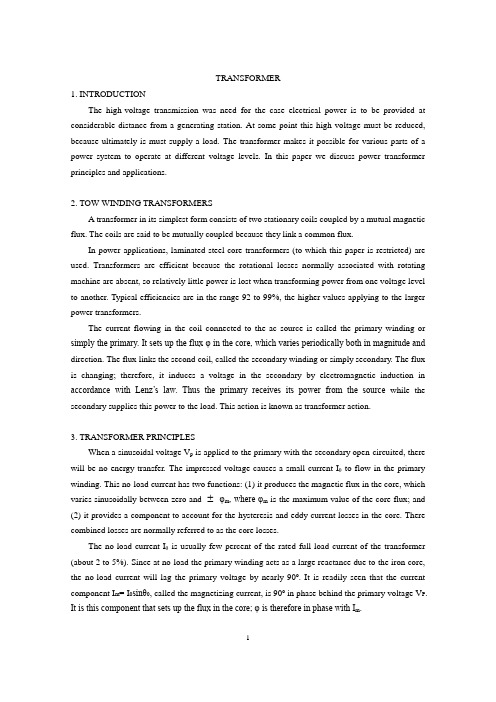
TRANSFORMER1. INTRODUCTIONThe high-voltage transmission was need for the case electrical power is to be provided at considerable distance from a generating station. At some point this high voltage must be reduced, because ultimately is must supply a load. The transformer makes it possible for various parts of a power system to operate at different voltage levels. In this paper we discuss power transformer principles and applications.2. TOW-WINDING TRANSFORMERSA transformer in its simplest form consists of two stationary coils coupled by a mutual magnetic flux. The coils are said to be mutually coupled because they link a common flux.In power applications, laminated steel core transformers (to which this paper is restricted) are used. Transformers are efficient because the rotational losses normally associated with rotating machine are absent, so relatively little power is lost when transforming power from one voltage level to another. Typical efficiencies are in the range 92 to 99%, the higher values applying to the larger power transformers.The current flowing in the coil connected to the ac source is called the primary winding or simply the primary. It sets up the flux φ in the core, which varies periodically both in magnitude and direction. The flux links the second coil, called the secondary winding or simply secondary. The flux is changing; therefore, it induces a voltage in the secondary by electromagnetic induction in accordance with Lenz’s law. Thus the primary receives its power from the source while the secondary supplies this power to the load. This action is known as transformer action.3. TRANSFORMER PRINCIPLESWhen a sinusoidal voltage V p is applied to the primary with the secondary open-circuited, there will be no energy transfer. The impressed voltage causes a small current Iθ to flow in the primary winding. This no-load current has two functions: (1) it produces the magnetic flux in the core, which varies sinusoidally between zero and φm, where φm is the maximum value of the core flux; and (2) it provides a component to account for the hysteresis and eddy current losses in the core. There combined losses are normally referred to as the core losses.The no-load current Iθ is usually few percent of the rated full-load current of the transformer (about 2 to 5%). Since at no-load the primary winding acts as a large reactance due to the iron core, the no-load current will lag the primary voltage by nearly 90º. It is readily seen that the current component I m= I0sinθ0, called the magnetizing current, is 90º in phase behind the primary voltage V P. It is this component that sets up the flux in the core; φ is therefore in phase with I m.The second component, I e =I 0sinθ0, is in phase with the primary voltage. It is the currentcomponent that supplies the core losses. The phasor sum of these two components represents theno-load current, orI 0 = I m + I eIt should be noted that the no-load current is distortes and nonsinusoidal. This is the result of thenonlinear behavior of the core material.If it is assumed that there are no other losses in the transformer, the induced voltage In theprimary, E p and that in the secondary, E s can be shown. Since the magnetic flux set up by theprimary winding ,there will be an induced EMF E in the secondary winding in accordance withFaraday’s law, namely, E=NΔφ/Δt. This same flux also links the primary itself, inducing in it anEMF, E p . As discussed earlier, the induced voltage must lag the flux by 90º, therefore, they are 180ºout of phase with the applied voltage. Since no current flows in the secondary winding, E s =V s . Theno-load primary current I 0 is small, a few percent of full-load current. Thus the voltage in theprimary is small and V p is nearly equal to E p . The primary voltage and the resulting flux aresinusoidal; thus the induced quantities E p and E s vary as a sine function. The average value of the induced voltage given byE avg= turns× change in flux in a given time given timewhich is Faraday’s law applied to a f inite time interval. It follows that E avg = N21/(2)m f = 4fNφm which N is the number of turns on the winding. Form ac circuit theory, the effective orroot-mean-square (rms) voltage for a sine wave is 1.11 times the average voltage; thusE = 4.44fNφmSince the same flux links with the primary and secondary windings, the voltage per turn in eachwinding is the same. HenceE p = 4.44fN p φmandE s = 4.44fN s φmwhere E p and Es are the number of turn on the primary and secondary windings, respectively. Theratio of primary to secondary induced voltage is called the transformation ratio. Denoting this ratioby a, it is seen thata = p sE E = p s N N Assume that the output power of a transformer equals its input power, not a bad sumption inpractice considering the high efficiencies. What we really are saying is that we are dealing with anideal transformer; that is, it has no losses. ThusP m = P outorV p I p × primary PF = V s I s × secondary PFwhere PF is the power factor. For the above-stated assumption it means that the power factor onprimary and secondary sides are equal; thereforeV p I p = V s I s from which is obtainedp s V V = p s I I ≌ p sE E ≌ a It shows that as an approximation the terminal voltage ratio equals the turns ratio. The primary and secondary current, on the other hand, are inversely related to the turns ratio. The turns ratio givesa measure of how much the secondary voltage is raised or lowered in relation to the primary voltage.To calculate the voltage regulation, we need more information.The ratio of the terminal voltage varies somewhat depending on the load and its power factor.In practice, the transformation ratio is obtained from the nameplate data, which list the primary andsecondary voltage under full-load condition.When the secondary voltage V s is reduced compared to the primary voltage, the transformationis said to be a step-down transformer: conversely, if this voltage is raised, it is called a step-uptransformer. In a step-down transformer the transformation ratio a is greater than unity (a>1.0), whilefor a step-up transformer it is smaller than unity (a<1.0). In the event that a=1, the transformersecondary voltage equals the primary voltage. This is a special type of transformer used in instanceswhere electrical isolation is required between the primary and secondary circuit while maintainingthe same voltage level. Therefore, this transformer is generally knows as an isolation transformer.As is apparent, it is the magnetic flux in the core that forms the connecting link betweenprimary and secondary circuit. In section 4 it is shown how the primary winding current adjusts itselfto the secondary load current when the transformer supplies a load.Looking into the transformer terminals from the source, an impedance is seen which bydefinition equals V p / I p . Fromp s V V = p s I I ≌ p sE E ≌ a , we have V p = aV s and I p = I s /a.In terms of V s and I s the ratio of V p to I p is p p V I = /s s aV I a = 2s sa V I But V s / I s is the load impedance Z L thus we can say thatZ m (primary) = a2Z LThis equation tells us that when an impedance is connected to the secondary side, it appears from the source as an impedance having a magnitude that is a2 times its actual value. We say that the load impedance is reflected or referred to the primary. It is this property of transformers that is used in impedance-matching applications.4. TRANSFORMERS UNDER LOADThe primary and secondary voltages shown have similar polarities, as indicated by the “dot-making” convention. The dots near the upper ends of the windings have the same meaning as in circuit theory; the marked terminals have the same polarity. Thus when a load is connected to the secondary, the instantaneous load current is in the direction shown. In other words, the polarity markings signify that when positive current enters both windings at the marked terminals, the MMFs of the two windings add.Since the secondary voltage depends on the core flux φ0, it must be clear that the flux should not change appreciably if E s is to remain essentially constant under normal loading conditions. With the load connected, a current I s will flow in the secondary circuit, because the induced EMF E s will act as a voltage source. The secondary current produces an MMF N s I s that creates a flux. This flux has such a direction that at any instant in time it opposes the main flux that created it in the first place. Of course, this is Lenz’s law in action. Thus the MMF represented by N s I s tends to reduce the core flux φ0. This means that the flux linking the primary winding reduces and consequently the primary induced voltage E p, This reduction in induced voltage causes a greater difference between the impressed voltage and the counter induced EMF, thereby allowing more current to flow in the primary. The fact that primary current I p increases means that the two conditions stated earlier are fulfilled: (1) the power input increases to match the power output, and (2) the primary MMF increases to offset the tendency of the secondary MMF to reduce the flux.In general, it will be found that the transformer reacts almost instantaneously to keep the resultant core flux essentially constant. Moreover, the core flux φ0 drops very slightly between n o load and full load (about 1 to 3%), a necessary condition if E p is to fall sufficiently to allow an increase in I p.On the primary side, I p’ is the current that flows in the primary to balance the demagnetizing effect of I s. Its MMF N p I p’sets up a flux linking the primary only. Since the core flux φ0 remains constant. I0 must be the same current that energizes the transformer at no load. The primary current I p is therefore the sum of the current I p’ and I0.Because the no-load current is relatively small, it is correct to assume that the primary ampere-turns equal the secondary ampere-turns, since it is under this condition that the core flux isessentially constant. Thus we will assume that I0 is negligible, as it is only a small component of the full-load current.When a current flows in the secondary winding, the resulting MMF (N s I s) creates a separate flux, apart from the flux φ0 produced by I0, which links the secondary winding only. This flux does no link with the primary winding and is therefore not a mutual flux.In addition, the load current that flows through the primary winding creates a flux that links with the primary winding only; it is called the primary leakage flux. The secondary- leakage flux gives rise to an induced voltage that is not counter balanced by an equivalent induced voltage in the primary. Similarly, the voltage induced in the primary is not counterbalanced in the secondary winding. Consequently, these two induced voltages behave like voltage drops, generally called leakage reactance voltage drops. Furthermore, each winding has some resistance, which produces a resistive voltage drop. When taken into account, these additional voltage drops would complete the equivalent circuit diagram of a practical transformer. Note that the magnetizing branch is shown in this circuit, which for our purposes will be disregarded. This follows our earlier assumption that the no-load current is assumed negligible in our calculations. This is further justified in that it is rarely necessary to predict transformer performance to such accuracies. Since the voltage drops are all directly proportional to the load current, it means that at no-load conditions there will be no voltage drops in either winding.变压器1. 介绍要从远端发电厂送出电能,必须应用高压输电。
变压器专业词汇英文翻译(DOC)
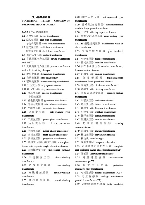
变压器常用术语TECHNICAL TERMS COMMONLY USED FOR TRANSFORMERPART 1产品名称及类型1.1电力变压器Power transformer1.2芯式变压器core type transformer内铁式变压器core-form transformer 1.3壳式变压器shell-form transformer外铁式变压器shell-form transformer 1.4 密封式变压器sealed transformer1.5 有载调压电力变压器power transformer with OLTC1.6 无载调压电力变压器power transformer with off-circuit tap-changer1.7 配电变压器distribution transformer1.8 自耦变压器auto-transformer1.9 联络变压器interconnecting transformer 1.10升压变压器step-up transformer1.11降压变压器step-down transformer1.12 增压变压器booster transformer串联变压器1.13 发电机变压器generator transformer 1.14 电站用变压器substation transformer 1.15 交流变压器converter transformer 1.16 分裂变压器split-winding type transformer1.17 厂用变压器power plant transformer 1.18 所用变压器electric substation transformer1.19 单相变压器single-phase transformer 1.20 三相变压器three-phase transformer 1.21 多相变压器polyphase transformer 1.22 单相变压器组成的三相组three-phase banks with separate single-phase transformer 1.23 三相接地变压器three-phase earthing transformer1.24 三线圈变压器three-winding transformer1.25 两线圈变压器two-winding transformer1.26 双线圈变压器double-winding transformer1.27 多线圈变压器multi-winding transformer 1.28 油浸式变压器oil-immersed type transformer1.29 浸难燃油变压器noninflammable medium impregnated transformer1.30 干式变压器dry type transformer1.31 树脂浇注式变压器resin-casting type transformer1.32 H级绝缘变压器transformer with H class insulation1.33 气体绝缘变压器gas insulated transformer1.34 电炉变压器furnace transformer1.35 整流变压器rectifier transformer1.36 列车牵引变压器traction transformer, locomotive transformer1.37 矿用变压器mining transformer1.38 防爆变压器explosion-proof transformer flame-proof transformer1.39 隔离变压器isolation transformer1.40 试验变压器testing transformer1.41 串级式试验变压器cascade testing transformer1.42 串联变压器series transformer1.43 增压变压器booster transformer1.44 灯丝变压器filament transformer1.45 电焊变压器welding transformer1.46 钎焊变压器brazing transformer1.47 船用变压器marine transformer1.48 起动自耦变压器starting autotransformer1.49 起动变压器starting transformer1.50 移动变压器movable substation1.51 移动式movable type1.52 成套变电站complete substation1.53 全自动保护单相变压器complete self-protected single-phase transformer(CSP) 1.54 互感器instrument transformer1.55 测量用互感器measurement current/voltage TR1.56 保护用互感器protective current/voltage transformer1.57 电流互感器current transformer(CT)1.58 电压互感器voltage transformer potential transformer(PT)1.59 全绝缘电流互感器fully insulatedcurrent transformer1.60 母线式电流互感器bus-type current transformer1.61 绕线式电流互感器wound primary type current transformer1.62 瓷箱式电流互感器porcelain type current transformer1.63 套管用电流互感器bushing-type current transformer1.64 电容式电流互感器capacitor type current transformer1.65 支持式电流互感器support-type current transformer1.66 倒立式电流互感器reverse type current transformer1.67 塑料浇注式电流互感器cast resin current transformer1.68 钳式电流互感器split-core type current transformer1.69 速饱和电流互感器rapid-saturable current transformer1.70 串级式电流互感器cascade-type current transformer1.71 剩余电流互感器residual current transformer1.72 电容式电压互感器capacitor type voltage transformer1.73 接地电压互感器earthed voltage transformer1.74 不接地电压互感器unearthed voltage transformer1.75 组合式互感器combined instrument transformer1.76 剩余电压互感器residual voltage transformer1.77 移圈调压器moving-coil voltage transformer1.78 动线圈moving winding1.79 自耦调压器autoformer regulator1.80 接触调压器variac1.81 感应调压器induction voltage regulator 1.82 磁饱和调压器magnetic saturation voltage regulator1.83 电抗器reactor1.84 并联电抗器shunt reactor 1.85 串联电抗器series reactor1.86 饱和电抗器saturable reactor1.87 铁心电抗器iron core reactor1.88 空心电抗器air core reactor1.89 水泥电抗器concrete(cement) reactor 1.90 三相中性点接地电抗器three-phase neutral reactor1.92 单相中性点接地电抗器single-phase neutral earthing reactor1.93 起动电抗器starting reactor1.94 平衡电抗器smoothing /interphase reactor1.95 调幅电抗器modulation reactor1.96 消弧电抗器arc-suppression reactor 1.97 消弧线圈arc-suppression coil1.98 阻波器,阻波线圈wave trap coil1.99 镇流器ballast1.100 密闭式sealed type1.101 包封式enclosed type1.102 户外式outdoor type1.103 户内式indoor type1.104 柱上式pole mounting type1.105 移动式movable type1.106 列车式trailer mounted type1.107 自冷natural cooling (ONAN)1.108 风冷forced-air cooling (ONAF)1.109 强油风冷forced-oil forced-air cooling(ONAF)1.110 强油水冷forced-oil forced-water cooling (ONWF)1.111 强油导向冷却forced-directed oil cooling (OFAN)1.112 强油导向风冷却forced-directed forced-air oil cooling(ODAF)1.113 恒磁通调压constant flux voltage variation(CFVV)1.114 变磁通调压variable flux voltage variation(VFVV)1.115 混合调压combined voltage variation(CbVV)PART2 基础词汇2.1 千瓦kilowatt(kw)2.2 兆瓦megawatt(MW)2.3 京瓦gigawatt(GW)2.4 千伏kilovolt(kV)2.5 兆伏megavolt(MV)2.6 京电子伏giga-electron-volt(GEV)2.7 千伏安KVA2.8 兆伏安MV A2.9 京伏安GV A2.10 千乏kilovar(kV Ar)2.11 兆乏megavar(MV Ar)2.12 京乏gigavar(GV Ar)2.13 产品代号symbol of product2.14 产品型号type of product2.15 额定电压rated voltage2.16 额定容量rated power2.17 额定电流rated current2.18 连接组标号connection symbol, symbol of connection2.19 阻抗电压impedance voltage2.20 额定频率rated frequency2.21 空载损耗no-load loss2.22 涡流损耗eddy-current loss2.23 磁滞损耗hysteresis loss2.24 空载电流no-load current2.25 激磁电流exciting current2.26 负载损耗load loss2.27 附加损耗additional losses, supplementary load loss2.28 杂散损耗stray losses2.29 总损耗total losses2.30 损耗比loss ratio2.31 冷却方式type of cooling2.32 介质损耗dielectric loss2.33 介损角正切值loss tangent2.34 电压组合voltage combination2.35 电抗电压reactance voltage2.36 额定电压比rated voltage ratio2.37 电阻电压resistance voltage2.38 电压调整率voltage regulation2.39 相位差phase displacement2.40 相位差校验phase displacement verification2.41 零序阻抗zero-sequence impedance 2.42 短路阻抗short-circuit impedance2.43 磁通密度flux density2.44 电流密度current density2.45 安匝数number of ampere-turns2.46 轴向漏磁通axial leakage flux 2.47 径向漏磁通radial leakage flux2.48 循环电流circulating current2.49 热点hot spot2.50 最热点hottest spot2.51 局部过热local overheat2.52 有功输出active output2.53 满容量分接fully-power tapping2.54 额定级电压rated step voltage2.55 最大额定电压maximum rated voltage 2.56 最大额定电流maximum rated through-current2.57 绕组额定电压rated voltage of a winding2.58 额定短时电流rated short time current 2.59 额定短时热电流rated short thermal current2.60 额定连续热电流rated continuous current2.61 额定动稳定电流rated dynamic current 2.62 一次电流/电压primary current/voltage 2.63 二次电流/电压secondary current/voltage2.64 实际电流比actual transformation ratio of a current transformer2.65 实际电压比actual transformation ratio of a voltage transformer2.66 二次极限感应电动势secondary limiting e.m.f.2.67 互感器的二次回顾路secondary circuit of CT and PT2.68 定额rating2.69 铁心噪声noise of core2.70 背境噪声background noise2.71 噪声水平noise level2.72 声级sound level2.73 声功率级sound power level2.74 声级试验sound level test2.75 声级测量sound level measurement 2.76水平加速度horizontal acceleration2.77 垂直加速度vertical acceleration2.78 地震seism, earthquake2.79 地震烈度earthquake intensity2.80 工频power-frequency2.81 中频medium frequency2.82 高频high frequency2.83 振荡频率oscillating frequency2.84 谐振频率resonance frequency2.85 自振频率natural frequency of vibration 2.86 频率响应frequency response2.87 谐波测量harmonics measurement2.88 绝缘水平insulation level2.89 绝缘强度insulation strength, dielectric strength2.90 主绝缘main insulation2.91 纵绝缘longitudinal insulation2.92 内绝缘internal insulation2.93 外绝缘external insulation2.94 绝缘配合insulation co-ordination2.95 全绝缘uniform insulation2.96 半绝缘non-uniform insulation2.97 降纸绝缘reduced insulation2.98 中心点neutral point2.99 中心点端子neutral terminal2.100 正常绝缘normal insulation2.101 介电常数dielectric constant2.102 油纸绝缘系统oil-paper insulation system2.103 绝缘电阻insulation resistance2.104 绝缘电阻吸收比absorption ratio of insulation resistance2.105 绝缘击穿insulation breakdown2.106 碳化carbonization2.107 爬电距离creepage distance2.108 沿面放电creeping discharge2.109 放电discharge2.110 局部放电partial discharge2.111 局部放电测量measurement of partial discharge2.112 超声定位ultrasonic location, ultrasonic orientation2.113 破坏性放电disruptive discharge2.114 局部放电起始电压partial discharge inception voltage2.115 局部放电终止电压partial discharge extinction voltage2.116 过电压overvoltage2.117 短时过电压short time overvoltage 2.118 瞬时过电压transient overvoltage2.119 操作过电压switching overvoltage 2.120 大气过电压atmospheric overvoltage 2.121 额定耐受电压rated withstand voltage 2.122 工频耐受电压power-frequency withstand voltage2.123 感应耐压试验induced overvoltage withstand test2.124 温升试验temperature-rise test2.125 温升temperature rise2.126 突发短路试验short-circuit test2.127 动热稳定thermo-dynamic stability 2.128 冲击耐压试验impulse voltage withstand test2.129 雷电冲击耐受电压lightning impulse withstand voltage2.130 操作冲击耐受电压switching impulse withstand voltage2.131 雷电冲击lightning impulse2.132 全波雷电冲击full wave lightning impulse2.133 截波雷电冲击chopped wave lightning impulse2.134 操作冲击switching impulse2.135 操作冲击波switch surge, switch impulse2.136 伏秒特性voltage-time characteristics 2.137 截断时间time to chopping2.138 波前时间time to crest2.139 视在波前时间virtual front time2.140 半峰值时间time to half value crest 2.141 峰值peak value, crest value2.142 有效值root-mean-square value2.143 标么值per unit value2.144 标称值nominal value2.145 电级electrode2.146 电位梯度potential gradient2.147 等电位,等位equipotential2.148 屏蔽shielding2.149 静电屏蔽electrostatic shielding2.150 磁屏蔽magnetic shielding2.151 静电屏electrostatic screen2.152 静电板electrostatic plate2.153 静电环electrostatic ring2.154 电磁感应electro-magnetic induction 2.155 电磁单元electro-magnetic unit2.156 有效面effective surface2.157 标准大气条件standard atmosphericcondition2.158 视在电荷apparent charge2.159 体积电阻volume resistance2.160 导电率admittance2.161 电导conductance, conductivity2.162 电晕放电corona discharge2.163 闪络flashover2.164 避雷器surge arrestor2.165 避雷器的残压residual voltage of an arrestor2.166 绝缘材料耐温等级temperature class of insulation2.167 互感器额定负荷rated burden of an instrument transformer2.168 准确级次accuracy class2.169 真值true value2.170 允差tolerance2.171 比值误差校验ratio error verification 2.172 电流误差current error2.173 电压误差voltage error2.174 互感器相角差phase displacement of instrument transformer2.175 复合误差composite error2.176 瞬时特性transient characteristic2.177 瞬时误差transient error2.178 额定仪表保安电流rated instrument security current2.179 二次极限感应电势secondary limitinge.m.f2.180 保安因子security factor2.181 额定准确限值的一次电流rated accuracy limit primary current2.182 误差补偿error compensation2.183 额定电压因子rated voltage factor 2.184 准确限值因子accuracy limit factor 2.185 开断电流switched current2.186 笛卡尔坐标,直角坐标Cartesian coordinate2.187 极坐标polar coordinate2.188 横坐标abscissa2.189 纵坐标ordinate2.190 X-轴X-axis2.191 复数complex number2.192 实数部分real component2.193 虚数部分imaginary component 2.194 正数positive number2.195 负数negative number2.196 小数decimal2.197 四舍五入round off2.198 分数fraction2.199 分子numerator2.200 分母denominator2.201 假分数improper fraction2.202 钝角obtuse angle2.203 锐角acute angle2.204 补角supplementary angle2.205 余角complement angle2.206 平行parallel2.207 垂直perpendicular2.208 乘方involution2.209 开方evolution, extraction of root2.210 n的5次方5th power of n2.211 幂exponent, exponential2.212 微分,差动differential, differentiate 2.213 积分,集成integral, integrate2.214 成正比proportional to….2.215 成反比inversely proportional to…2.216 概率probability2.217 归纳法inductive method2.218 外推法extrapolation method2.219 插入法interpolation method2.220 最大似然法maximum likelihood method2.221 图解法graphic method2.222 有限元法finite element method2.223 模拟法simulation method2.224 方波回应step response2.225 迭加电荷superimposed charge2.226 杂散电容stray capacitance2.227 无损探伤non-distractive flaw detection2.228 红外线扫描infrared scanning2.229 计算机辅助设计computer aided design(CAD)2.230 计算机辅助制造computer aided manufacturing(CAM)2.231 计算机辅助试验computer aided test(CAT)2.233 近似于approximate(approx)2.234 每分钟转数revolution perminute(rpm)2.235 速度velocity2.236 加速度acceleration2.237 重力加速度gravitational acceleration 2.238 引力traction2.240 件数pieces2.242 缩写abbreviation2.243 以下简称为hereinafter referred as xxx2.244 常用单位units commonly used2.245 包括缩写including abbreviations2.246 分米decimeter 厘米centimeter2.247 海里knot2.248 码yard2.249 磅pound(1b) 磅/平方英寸pound per square inch(ppsi)2.251 英制热量单位British thermal unit (BTU)2.252 马力horsepower2.253 压强intensity of pressure2.254 帕斯卡Pascal(Pa)2.255 千帕kpa 兆帕Mpa2.256 粘度viscosity2.257 帕斯卡秒pascal.second2.258 泊poise 厘泊centipoises2.259 焦耳joule(J) 千瓦时kilowatt-hour(kwh)2.260 特斯拉tesla(T) 高斯gaue(Gs)2.261 奥斯特oersted(0e) 库仑coulomb(C) 2.262 微微库Pico-coulomb(PC)2.263 达因dyne2.264 摄氏度Celsius, centigrade(℃)2.265 开尔文Kelvin 法拉farad(F)2.266 皮可法拉pico-farad(pF)2.268 立方分米cubic decimeter立方厘米cubic centimeter2.269 桶barrel 石油petroleum2.270 标准国际单位制standard international unit2.271 厘米-克秒单位制CGS unit2.272 环境设备ambience apparatus2.273 校验calibration2.274 兼容性compatibility2.275 扩散系数diffusion coefficient2.276 故障fault 2.277 公顷hectarePART3 典型产品结构3.1 芯式,内铁式core type3.2 壳式,外铁式shell type3.3 铁心core3.4 磁路magnetic circuit3.5 线圈winding, coil3.6 高压线圈HV winding3.7 中压线圈MV winding3.8 低压线圈LV winding3.9 调压线圈tapped winding, regulating winding3.10 高压引线high-voltage leads3.11 中压引线mid-voltage leads3.12 低压引线low-voltage leads3.13 夹件clamping frame3.14 上部夹件upper clamping3.15 下部夹件lower clamping3.16线圈压紧螺栓winding compressing bolt 3.17线圈压紧装置winding compressing device3.18 线圈端部绝缘end insulation of winding3.19 器身定位装置positioning device for active-part3.20 定位装置fixing device3.21 铁心垫脚foot-plate of core3.22 垫脚foot-pad3.23 分接引线tapping leads, tap leads3.24 引线支架supporting frame for leads 3.25 无励磁分接开关non-excitation tap-changer3.26 无载分接开关off-circuit tap-changer 3.27 分接选择器tap selector3.28 有载分接开关on-load tap-changer(OLTC) on-circuit tap-changer 3.29 切换开关diverter switch3.30 选择开关selector switch3.31 转换选择器change-over selector3.32 粗选择器coarse tap selector3.33 触头组set of contacts3.34 过度触头transition contacts3.35 过度阻抗transition impedance3.36 有载开关操纵机构operating mechanism of OLTC3.37 驱动机构driving mechanism3.38 电动机构motor drive3.39 垂直转动轴vertical driving shaft水平转动轴horizontal driving shaft 3.40 伞尺轮盒bevel gear box3.41 防雨罩drip-proof cap3.42 联轴节coupling3.43 最大分接maximum tapping最小分接minimum tapping3.44 额定分接rated tapping, principal tapping3.45 固定分接位置数number of inherent tapping positions工作分接位置数number of service tapping positions3.46 主分接principal tap, main tap正分接plus tapping负分接minus tapping3.47 分接变换操作tap-changer operation 3.48 分接位置指示器tap position indicator 3.49 线圈分接电压tapping voltage of a winding3.50 线圈分接电流tapping current of a winding3.51 线圈分接容量tapping power of a winding3.52 分接范围tapping range3.53 分接量tapping quantities3.54 分接因子tapping factor3.55 分接工作能力tapping duty3.56 分接线tapping step3.57 分接线tapping connection3.58 分接引线tapping lead3.59 小车支架及滚轮bogie frame and wheel3.61 箱底tank bottom3.62 箱盖tank cover3.63 箱沿tank rim3.64 垫脚垫块supporting block for foot-pad 3.65 联管接头tube connector3.66 联接法兰connecting flange3.67 加强筋,加强板stiffener3.68 油箱垂直加强铁vertical stiffening channel of tank wall3.69 油箱活门oil sampling valve3.70 放油活门oil drainningvalve 3.71 冷却器cooler3.72 集中安装concentrated installation3.73 集中安装强油循环风冷器concentrated installation of forced-oil circulating air cooler3.74 冷却器进口inlet of cooler冷却器出口outlet of cooler3.75 潜油泵oil-submerged pump3.76 油流继电器oil flow relay3.77 净油器oil filter3.78 虹吸净油器oil siphon filter3.79 散热器radiator3.80 片式散热器panel type radiator3.81 管式散热器tubular radiator3.82 放油塞oil draining plug3.83 放气塞air exhausting plug3.84 蝶阀radiator valve butterfly valve 3.85 风扇支架supporting frame for fan motors3.86 风扇及电机fan and motor3.87 风扇接线盒connecting box for fan motors3.88 储油柜conservator3.89 油位计oil-level indicator3.90 气体继电器gas relay, buchholz realy 3.91 皮托继电器pitot relay3.92 储油柜联管elbow joint for conservator 3.93 有载开关用储油柜conservator for OLTC3.94 有载开关用气体继电器gas relay for OLTC3.95 联管tube connector3.96 吸湿器dehydrating breather3.97 铭牌rating plate3.98 温度计thermometer3.98 指示仪表柜cabinet panel for indicating instruments3.99 风扇控制柜cabinet panel for fan motor control3.100 压力释放阀pressure-relief valve3.101 安全气道explosion-proof pope3.102 膨胀器expander3.103 主排气导管main gas-conduit3.104 分支导气管branching gas-conduit 3.105 滤油界面tube connector for oil-filter3.106 温度计座thermometer socket3.107 储油柜支架supporting frame for conservator3.108 高压套管HV bushing3.109 高压套管均压球equipotential shielding for HV bushing3.110 高压零相套管HV neutral bushing, HV bushing phase03.111 中压套管MV bushing3.112 中压零相套管MV neutral bushing, MV bushing phase03.113 低压套管LV bushing3.114 接地套管earthing bushing3.115 极性polarity3.116 极化polarization3.117 高压套管储油柜conservator for HV bushing3.118 相间隔板interphase insulating barrier 3.119 吊攀lifting lug3.120 安装轨道installation rail3.121 相序标志牌designation mark of phase sequence3.122 接地螺栓earthing bolt3.123 视察窗inspection hole3.124 手孔handhole3.125 人孔manhole3.126 MR有载开关MR OLTC3.127 ABB 有载开关ABB OLTC3.128 伊林有载开关ELIN OLTC3.129 F&套管F&G bushingPART4 铁心结构4.1 多框式铁心multi-frame type core4.2 三相三柱铁心three-phase three-limb core4.3 三相五柱铁心three-phase five-limb core4.4 卷铁心wound core4.5 冷轧晶粒取向硅钢片cold-rolled grain-oriented silicon sheet steel4.6 晶粒crystalline grain4.7 高导磁硅钢片HI-B silicon sheet steel 4.8 铁心片core lamination4.9 一迭铁心a lamination stock4.10 铁心迭积图lamination drawing, lamination diagram 4.11 迭片lamination4.12 迭片系数lamination factor4.13 空间利用系数space factor4.14 层间绝缘layer insulation4.15 斜接缝mitring4.16 45°斜接缝45°mitred joint4.17 斜接缝的交错排列方式over-lay arrangement for mitred joints of lamination 4.18 重迭overlap4.19 铁心油通oil-duct of core4.20 铁心气道air ventilating duct of core 4.21 阶梯接缝stepped lay joint4.22 对接铁心butt jointed core4.23 渐开线铁心evolute core, involute core 4.24 空气隙air gap4.25 铁心拉板tensile plate of core limb, core drawplate4.26 铁心柱core limb, core lge4.27 轭,铁轭yoke4.28 上轭upper yoke下轭lower yoke旁轭side yoke, return yoke4.29 环氧绑扎带epoxy-bonded bandage 4.30 轭拉带yoke tensile belt4.31 铁轭拉带banded band of core yoke 4.32 上轭顶梁top jointing beam of upper yoke4.33 侧梁side beam4.34 夹件clamping frame4.35 铁心夹件core clamps, coreframe4.36 铁轭夹件yoke clamping, yoke clamps 4.37 上夹件upper yoke clamping, upper yoke clamps4.38 下夹件lower yoke clampings, lower yoke clamps4.39 夹件腹板web of yoke clamping4.40 夹件肢板limb of yoke clamping4.41 夹件加强stiffening plate of clamping 4.42 压线圈的压钉winding compressing bolt4.43 压钉螺母nut for compressing bolt4.44 弹簧压钉compressing bolt with spring 4.45 油缸压钉compressing bolt with hydraulic damper4.46 线圈支撑架winding supporter4.47 线圈支撑架winding supporting plate 4.48 垫脚foot pad4.49 定位孔positioning hole4.50 带螺母的定位柱positioning stud4.51 拉螺杆tensile rod4.52 夹件夹紧螺杆yoke clamping bolt4.53 铁心接地片core earthing strip4.54 铁心地屏earthing screen of code4.55 旁轭地屏earthing screen of side yoke 4.56 接地屏蔽earthing shield4.57 铁心窗高core window height4.58 中心距M center line distance M4.59 铁心中间距center distance between lombs4.60 木垫块wood padding block4.61 迭片系数lamination factor4.62 铁心的级stage of lamination stacks 4.63 心柱外接圆circumscribed circle of core leg4.64 铁心端面core surface perpendicular to lamination4.65 木棒wood bar, wood rod4.66 定位板positioning platePART5 线圈结构5.1 圆筒式线圈cylindrical winding5.2 层式线圈layer winding5.3 饼式线圈disk winding5.4 单层圆筒式线圈single layer cylindrical winding5.5 双层圆筒式线圈double layer cylindrical winding5.6 多层圆筒式线圈multi-layer cylindrical winding5.7 大型层式线圈large size long layer winding5.8 分段圆筒式线圈sectional layer winding 5.9 分段多层圆筒线圈sectional multi-layer winding5.10 连续式线圈continuous winding5.11 半连续式线圈semi-continuous winding5.12 纠结式线圈interleaved winding5.13 纠结饼式线圈interleaved disc winding 5.14 纠结—连续式线圈interleaved-continuous winding 5.15 部分纠结式线圈partial-interleaved winding5.16 插花纠结式线圈sandwich-interleaved winding5.17 内屏连续式线圈innershield-continuous winding5.18 插入电容式线圈capacitor shield winding5.19 高串联电容线圈high series capacitance winding5.20 双饼式线圈twin-disk winding5.21 交错式线圈sandwich winding, staggered winding5.22 螺旋式线圈helical winding, helix winding5.23 半螺旋式线圈semi-helical winding 5.24 单列螺旋式线圈single-row helical winding5.25 双列螺旋式线圈double-row helical winding5.26 三列螺旋式线圈three-row helical winding5.27 短螺旋式线圈short helical winding 5.28 螺旋式线圈引出端的固定terminal fixing for helical winding5.29 分裂式线圈split winding5.30 分段式线圈sectional winding5.31 箔式线圈foil winding5.32 全绝缘线圈uniformly insulated winding5.33 分级绝缘线圈gradedly insulated winding, winding with non-uniform insulation 5.34 第三线圈tertiary winding5.35 高压线圈high-voltage winding5.36 中压线圈mid-voltage winding, intermediate voltage winding5.37 低压线圈low-voltage winding5.38 调压线圈regulating winding, tapped winding5.39 辅助线圈auxiliary winding5.40 平衡线圈balance winding5.41 稳定线圈stabilizing winding5.42 公共线圈common winding5.43 串联线圈series winding5.44 连耦线圈coupling winding5.45 励磁线圈exciting winding, energizing winding5.46 一次线圈primary winding5.47 二次线圈secondary winding5.48 左绕left-wound5.49 右绕right-wound5.50 星形联结star connection5.51 三角形联结delta connection5.52 曲折形联结zigzag connection5.53 T形联结scott connection5.54 开口三角形联结open-delta connection 5.55 开口线圈open winding5.57 线段winding disk, winding section5.58 线层winding layer5.59 匝绝缘turn insulation5.60 层绝缘layer insulation5.61 段绝缘insulation between disks, section insulation5.62 端绝缘end insulation5.63 顶部端环top support ring5.64 分接头tapping terminal5.65 分接区tapping zone5.66 段间横垫块radial spacer between disks 5.67 燕尾垫块chock5.68 燕尾撑条dovetail strip5.69 垫块的厚度spacer thickness5.70 垫块的宽度spacer width5.71 撑条stick, duct strip5.72 轴向撑条axial strip5.73 油道oil-duct, oil passage5.74 径向油道radial oil-duct5.75 段间油道oil-duct between disks5.76 段间过度联线transfer connection between disks5.77 段间换位联线transposed connection between disks5.78 S弯S-bend5.79 线圈起始端initial terminal of winding 5.80 线圈终端final terminal of winding5.81 轴向深度axial depth5.82 径向深度radial depth5.83 绝缘纸筒insulating cylinder5.84 匝间绝缘turn insulation5.85 绝缘角环insulating angled ring (collar ring) 5.86 线匝间垫条insulating filling strips between turns5.87 分数匝fractional turn5.88 整数匝integer turn5.89 近似一圈approximate roll5.90 并绕导线parallel wound conductors 5.91 多股导线multi-strand conductors5.92 电磁线electro-magnetic conductor5.93 组合导线composite conductor5.94 换位导线transposed conductor, transposed cable5.95 纸包线paper wrapped conductor5.96 纸包导线covered conductor5.97 漆包线enameled conductor5.98 圆线round wire5.99 硬拉铜导线hard drawn copper conductor5.100 退火导线annealed conductor5.101 玻璃丝包线glass-fiber covered conductor5.102 纸槽paper channel5.103 绑线binding wire5.104 绑绳binding rope5.105 静电板electrostatic plate5.106 静电环electrostatic ring5.107 端部电容环capacitive layer end ring 5.108 端部电容屏capacitive layer end screen5.109 屏蔽环shielding ring5.110 屏蔽线shielding conductor5.111 屏蔽角环shroud petal5.112 绝缘包扎insulation wrapping5.113 线圈总高度overall height of winding 5.114 铜线高度copper height of winding 5.115 线圈调整trimming of winding5.116 线圈浸漆varnish impregnation of winding5.117 线圈的换位transposition of winding 5.118 标准换位standard transposition5.119 分组换位transposition by groups5.120 线圈展开图planiform drawing of winding5.121 线圈的干燥与压缩drying and compressing of winding5.122 绝缘的压缩收缩率shrinkage ofinsulation under compression5.123 无氧铜导线deoxygenized copper conductor5.124 铝合金导线aluminum-alloy conductorPART6 油箱结构及附件6.1 钟罩式油箱bell type tank6.2 上节油箱upper part of tank6.3 下节油箱bottom part of tank6.4 箱壁tank wall6.5 带磁屏箱壁tank wall with magnetic shield6.6 箱底tank bottom6.7 箱盖tank cover6.8 箱沿tank rim6.9 箱沿护框pad frame for tank rim gasket 6.10 边缘垫片rim6.11 加强筋,加强板stiffener6.12 联管头tube connecting flange6.13 放油活门draining valve6.14 油样活门oil sampling valve6.15 油样活塞oil sampling plug6.16 闸阀gate valve6.17 蝶阀butterfly valve6.18 球阀ball valve6.19 压力释放阀pressure relief valve6.20 安全气道explosion-proof pipe6.21 真空接头connecting flange for evacuation6.22 滤油接头connecting flange for oil filter6.23 水银温度计pocket for mercury thermometer6.24 铭牌底板base plate of rating plate6.25 手孔handhole6.26 人孔manhole6.27 升高座ascending flanged base turret 6.28 吊攀lifting lug6.29 千斤顶支座jacking lug6.30 定位钉positioning pin6.31 盖板cover plate6.32 临时盖板temporary cover plate6.33 带隔膜储油柜conservator with rubber diaphragm6.34 带胶囊储油柜conservator with rubber bladder6.35 沉淀盒precipitation well6.36 导气管air exhausting pipe6.37 导油管oil conduit6.38 吊环lifting eyebolt6.39 有围栏的梯子ladder with balustrade 6.40 适形油箱form-fit tank6.41 呼吸器breather6.42 气体继电器gas relay, buchholz relay 6.43 皮托继电器pitot relay6.44 流动继电器flow relay6.45 风冷却器air cooler6.46 水冷却器water cooler6.47 冷却器托架bracket for cooler6.48 冷却器拉杆tensile rod for cooler6.49 潜油泵oil-submerged pump6.50 流量flow quantity6.51 扬程lift6.52 控制箱control box6.53 控制盘control panel6.54 端子箱terminal box6.55 端子排terminal block6.56 风扇接线盒connecting box for fan-motors6.57 金属软管metallic hose6.58 封闭母线联结法兰joint flange for enclosed bus-bar6.59 管式油位指示器tubular oil-level indicator6.60 磁铁式油位指示器magnetic type oil-level indicatorPART7 铁心制造7.1 产品制造manufacturing of products7.2 硅钢片纵剪silicon steel sheet slitting 7.3 硅钢片横剪silicon steel sheet cutting to length7.4 多刀滚剪机multi-disk-cutter slitting machine7.5 纵剪slitting横剪cut-to-length7.6 纵剪生产线slitting line7.7 横剪生产线cut-to-length line7.8 开卷机decoiler7.9 毛刺burr7.10 铁心片预迭pre-stacking of corelamination7.11 铁心迭装core assembly7.12 铁心迭片core lamination7.13 选片pre-selection of lamination7.14 迭片lamination stacking7.15 两片一迭stacked by two-sheet7.16 打(敲)齐knock to even7.17 迭装流转台core assembly tilting platform7.18 不迭上轭core stacking without upper yoke7.19 打铁心用垫块knock block7.20 铁心料盘lamination stocking tray7.21 卷铁心机core winding machine7.22 铁心退火core annealing7.23 铁心中间试验interprocess core test 7.24 片的角度偏差angular misalignment of lamination7.25 宽度偏差width deviation7.26 长度偏差length deviation7.27 铁心的垂直度verticality of core7.28 铁心起立tilt the core into vertical position7.29 迭片的定位挡板positioning stopper for core assembly7.30 硅钢片的涂漆varnish coating of silicon steel sheet7.31 片间绝缘试验lamination insulation test7.32 半导体粘带semi-conductive adhesive tape7.33 半干环氧粘带semi-cured epoxy adhesive tape7.34 粘带的固化cure of adhesive tape7.35 夹紧铁心工具clamping tools for core 7.36 铁心柱的夹紧装置tightening device for core leg7.37 铁心翻转台tilting platform of core 7.38 螺旋千斤顶screw jack7.39 水平尺level gauge, level instrument 7.40 专用套筒搬手special socket spanner 7.41 迭片的工艺孔punching hole on the lamination for manufacturing purpose7.42 迭板导棒guiding bar for core assembly 7.43 力短搬手torque spanner, torque wrench7.44 角度测量平台angular measuring platform7.45 切口防锈漆antirust coating for cutting edges7.46 铁心的油道撑条strips for core oil-ducts7.47 撑条粘结sticking of strips7.48 级间衬纸insulating paper between core stages7.48 冲孔模hole punching die7.49 缺口模notch punching die7.50 皮裙leather apron7.51 防护袖protective sleeve7.52 护臂shoulder guard7.53 护腿shin guardPART8 线圈制造8.1 绕线机,卷线机winding machine8.2 卧式绕线机horizontal winding machine 8.3 立式绕线机vertical winding machine 8.4 绕盘架bracket for conductor drums, bracket for wire drums8.5 导线盘conductor drum, wire drum8.6 导线拉紧装置conductor tensile device, wire tensile device8.7 导线复绕机conductor rewind machine 8.8 导线矫直机conductor straightening machine8.9 可调节绕线模adjustable winding drum 8.10 装配式绕线模fabricated winding drum 8.11 钢板筒绕线模steel-plate rolled winding drum8.12 模子直径former diameter8.13 线圈外径OD (outside diameter) of winding8.14 线圈内径ID (inside diameter) of winding8.15 半径radius8.16 木撑条wood supporting strips8.17 绝缘撑条insulating strips8.18 撑条号number of the strip, number of chock line8.19 正段线饼normally wound disks8.20 反段线饼reversely wound disks8.21 临时段线饼temporarily wound disks。
电气专业外文翻译---负载运行的变压器及直流电机导论
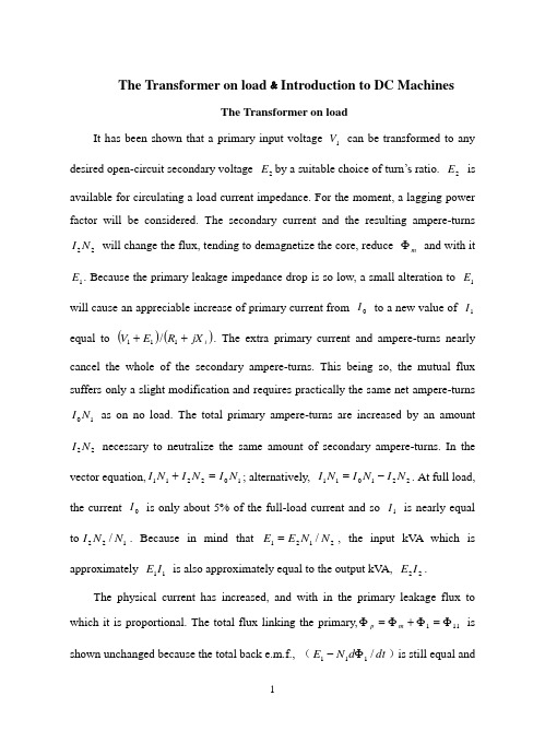
The Transformer on load ﹠Introduction to DC MachinesThe Transformer on loadIt has been shown that a primary input voltage 1V can be transformed to any desired open-circuit secondary voltage 2E by a suitable choice of turn’s ratio. 2E is available for circulating a load current impedance. For the moment, a lagging power factor will be considered. The secondary current and the resulting ampere-turns 22N I will change the flux, tending to demagnetize the core, reduce m Φ and with it 1E . Because the primary leakage impedance drop is so low, a small alteration to 1E will cause an appreciable increase of primary current from 0I to a new value of 1I equal to ()()i jX R E V ++111/. The extra primary current and ampere-turns nearly cancel the whole of the secondary ampere-turns. This being so, the mutual flux suffers only a slight modification and requires practically the same net ampere-turns 10N I as on no load. The total primary ampere-turns are increased by an amount 22N I necessary to neutralize the same amount of secondary ampere-turns. In the vector equation,102211N I N I N I =+; alternatively, 221011N I N I N I -=. At full load, the current 0I is only about 5% of the full-load current and so 1I is nearly equal to 122/N N I . Because in mind that 2121/N N E E =, the input kV A which is approximately 11I E is also approximately equal to the output kV A, 22I E .The physical current has increased, and with in the primary leakage flux to which it is proportional. The total flux linking the primary,111Φ=Φ+Φ=Φm p is shown unchanged because the total back e.m.f., (dt d N E /111Φ-)is still equal andopposite to 1V . However, there has been a redistribution of flux and the mutual component has fallen due to the increase of 1Φ with 1I . Although the change is small, the secondary demand could not be met without a mutual flux and e.m.f. alteration to permit primary current to change. The net flux s Φlinking the secondary winding has been further reduced by the establishment of secondary leakage flux due to 2I , and this opposes m Φ. Although m Φ and 2Φ are indicated separately, they combine to one resultant in the core which will be downwards at the instant shown. Thus the secondary terminal voltage is reduced to dt d N V S /22Φ-= which can be considered in two components, i.e. dt d N dt d N V m //2222Φ-Φ-=or vectorially 2222I jX E V -=. As for the primary, 2Φ is responsible for a substantially constantsecondary leakage inductance 222222/Λ=ΦN i N . It will be noticed that the primary leakage flux is responsible for part of the change in the secondary terminal voltage due to its effects on the mutual flux. The two leakage fluxes are closely related;2Φ, for example, by its demagnetizing action on m Φ has caused the changes on the primary side which led to the establishment of primary leakage flux.If a low enough leading power factor is considered, the total secondary flux and the mutual flux are increased causing the secondary terminal voltage to rise with load. p Φ is unchanged in magnitude from the no load condition since, neglecting resistance, it still has to provide a total back e.m.f. equal to 1V . It is virtually the same as 11Φ, though now produced by the combined effect of primary and secondary ampere-turns. The mutual flux must still change with load to give a change of 1E and permit more primary current to flow. 1E has increased this timebut due to the vector combination with 1V there is still an increase of primary current.Two more points should be made about the figures. Firstly, a unity turns ratio has been assumed for convenience so that '21E E =. Secondly, the physical picture is drawn for a different instant of time from the vector diagrams which show 0=Φm , if the horizontal axis is taken as usual, to be the zero time reference. There are instants in the cycle when primary leakage flux is zero, when the secondary leakage flux is zero, and when primary and secondary leakage flux is zero, and when primary and secondary leakage fluxes are in the same sense.The equivalent circuit already derived for the transformer with the secondary terminals open, can easily be extended to cover the loaded secondary by the addition of the secondary resistance and leakage reactance.Practically all transformers have a turn’s ratio different from unity although such an arrangement is sometimes employed for the purposes of electrically isolating one circuit from another operating at the same voltage. To explain the case where 21N N ≠ the reaction of the secondary will be viewed from the primary winding. The reaction is experienced only in terms of the magnetizing force due to the secondary ampere-turns. There is no way of detecting from the primary side whether 2I is large and 2N small or vice versa, it is the product of current and turns which causes the reaction. Consequently, a secondary winding can be replaced by any number of different equivalent windings and load circuits which will give rise to an identical reaction on the primary .It is clearly convenient to change the secondary winding to an equivalent winding having the same number of turns 1N as the primary.With 2N changes to 1N , since the e.m.f.s are proportional to turns, 2212)/('E N N E = which is the same as 1E .For current, since the reaction ampere turns must be unchanged 1222'''N I N I = must be equal to 22N I .i.e. 2122)/(I N N I =.For impedance, since any secondary voltage V becomes V N N )/(21, and secondary current I becomes I N N )/(12, then any secondary impedance, including load impedance, must become I V N N I V /)/('/'221=. Consequently, 22212)/('R N N R = and 22212)/('X N N X = .If the primary turns are taken as reference turns, the process is called referring to the primary side.There are a few checks which can be made to see if the procedure outlined is valid.For example, the copper loss in the referred secondary winding must be the same as in the original secondary otherwise the primary would have to supply a different loss power.''222R I Must be equal to 222R I . )222122122/()/(N N R N N I ∙∙ does in fact reduce to 222R I . Similarly the stored magnetic energy in the leakage field )2/1(2LI which is proportional to 22'X I will be found to check as ''22X I . The referred secondary 2212221222)/()/(''I E N N I N N E I E kVA =∙==.The argument is sound, though at first it may have seemed suspect. In fact, if the actual secondary winding was removed physically from the core and replaced by the equivalent winding and load circuit designed to give the parameters 1N ,'2R ,'2X and'2I , measurements from the primary terminals would be unable to detect any difference in secondary ampere-turns, kVA demand or copper loss, under normal power frequency operation.There is no point in choosing any basis other than equal turns on primary and referred secondary, but it is sometimes convenient to refer the primary to the secondary winding. In this case, if all the subscript 1’s are interchanged for the subscript 2’s, the necessary referring constants are easily found; e.g. 2'1R R ≈,21'X X ≈; similarly 1'2R R ≈ and 12'X X ≈. The equivalent circuit for the general case where 21N N ≠ except that m r has been added to allow for iron loss and an ideal lossless transformation has been included before the secondary terminals to return '2V to 2V .All calculations of internal voltage and power losses are made before this ideal transformation is applied. The behavior of a transformer as detected at both sets of terminals is the same as the behavior detected at the corresponding terminals of this circuit when the appropriate parameters are inserted. The slightly different representation showing the coils 1N and 2N side by side with a core in between is only used for convenience. On the transformer itself, the coils are, of course, wound round the same core.Very little error is introduced if the magnetizing branch is transferred to the primary terminals, but a few anomalies will arise. For example, the current shown flowing through the primary impedance is no longer the whole of the primary current. The error is quite small since 0I is usually such a small fraction of 1I . Slightly different answers may be obtained to a particular problem depending on whether or not allowance is made for this error. With this simplified circuit, the primary and referred secondary impedances can be added to give:221211)/(Re N N R R += And 221211)/(N N X X Xe +=It should be pointed out that the equivalent circuit as derived here is only valid for normal operation at power frequencies; capacitance effects must be taken into account whenever the rate of change of voltage would give rise to appreciable capacitance currents,dt CdV I c /=. They are important at high voltages and at frequencies much beyond 100 cycles/sec. A further point is not the only possible equivalent circuit even for power frequencies .An alternative , treating the transformer as a three-or four-terminal network, gives rise to a representation which is just as accurate and has some advantages for the circuit engineer who treats all devices as circuit elements with certain transfer properties. The circuit on this basis would have a turns ratio having a phase shift as well as a magnitude change, and the impedances would not be the same as those of the windings. The circuit would not explain the phenomena within the device like the effects of saturation, so for an understanding of internal behavior.There are two ways of looking at the equivalent circuit:(a) viewed from the primary as a sink but the referred load impedance connected across '2V ,or(b) Viewed from the secondary as a source of constant voltage 1V with internal drops due to 1Re and 1Xe . The magnetizing branch is sometimes omitted in this representation and so the circuit reduces to a generator producing a constant voltage 1E (actually equal to 1V ) and having an internal impedance jX R + (actually equal to 11Re jXe +).In either case, the parameters could be referred to the secondary winding and this may save calculation time.The resistances and reactances can be obtained from two simple light load tests.Introduction to DC MachinesDC machines are characterized by their versatility. By means of various combination of shunt, series, and separately excited field windings they can be designed to display a wide variety of volt-ampere or speed-torque characteristics for both dynamic and steady state operation. Because of the ease with which they can be controlled, systems of DC machines are often used in applications requiring a wide range of motor speeds or precise control of motor output.The essential features of a DC machine are shown schematically. The stator has salient poles and is excited by one or more field coils. The air-gap flux distribution created by the field winding is symmetrical about the centerline of the field poles. This axis is called the field axis or direct axis.As we know, the AC voltage generated in each rotating armature coil is converted to DC in the external armature terminals by means of a rotating commutator and stationary brushes to which the armature leads are connected. The commutator-brush combination forms a mechanical rectifier, resulting in a DC armature voltage as well as an armature m.m.f. wave which is fixed in space. The brushes are located so that commutation occurs when the coil sides are in the neutral zone, midway between the field poles. The axis of the armature m.m.f. wave then in 90 electrical degrees from the axis of the field poles, i.e., in the quadrature axis. In the schematic representation the brushes are shown in quadrature axis because this is the position of the coils to which they are connected. The armature m.m.f. wave then is along the brush axis as shown.. (The geometrical position of the brushes in an actual machine is approximately 90 electrical degrees from their position in the schematic diagram because of the shape of the end connections to the commutator.) The magnetic torque and the speed voltage appearing at the brushes areindependent of the spatial waveform of the flux distribution; for convenience we shall continue to assume a sinusoidal flux-density wave in the air gap. The torque can then be found from the magnetic field viewpoint.The torque can be expressed in terms of the interaction of the direct-axis air-gap flux per pole d Φ and the space-fundamental component 1a F of the armature m.m.f. wave . With the brushes in the quadrature axis, the angle between these fields is 90 electrical degrees, and its sine equals unity. For a P pole machine12)2(2a d F P T ϕπ= In which the minus sign has been dropped because the positive direction of the torque can be determined from physical reasoning. The space fundamental 1a F of the saw tooth armature m.m.f. wave is 8/2π times its peak. Substitution in above equation then givesa d a a d a i K i mPC T ϕϕπ==2 Where a i =current in external armature circuit;a C =total number of conductors in armature winding;m =number of parallel paths through winding;AndmPC K a a π2= Is a constant fixed by the design of the winding.The rectified voltage generated in the armature has already been discussed before for an elementary single-coil armature. The effect of distributing the winding in several slots is shown in figure, in which each of the rectified sine waves is thevoltage generated in one of the coils, commutation taking place at the moment when the coil sides are in the neutral zone. The generated voltage as observed from the brushes is the sum of the rectified voltages of all the coils in series between brushes and is shown by the rippling line labeled a e in figure. With a dozen or so commutator segments per pole, the ripple becomes very small and the average generated voltage observed from the brushes equals the sum of the average values of the rectified coil voltages. The rectified voltage a e between brushes, known also as the speed voltage, ism d a m d a a W K W mPC e ϕϕπ==2 Where a K is the design constant. The rectified voltage of a distributed winding has the same average value as that of a concentrated coil. The difference is that the ripple is greatly reduced.From the above equations, with all variable expressed in SI units:m a a Tw i e =This equation simply says that the instantaneous electric power associated with the speed voltage equals the instantaneous mechanical power associated with the magnetic torque, the direction of power flow being determined by whether the machine is acting as a motor or generator.The direct-axis air-gap flux is produced by the combined m.m.f. f f i N ∑ of the field windings, the flux-m.m.f. characteristic being the magnetization curve for the particular iron geometry of the machine. In the magnetization curve, it is assumed that the armature m.m.f. wave is perpendicular to the field axis. It will be necessary to reexamine this assumption later in this chapter, where the effects of saturation are investigated more thoroughly. Because the armature e.m.f. is proportional to fluxtimes speed, it is usually more convenient to express the magnetization curve in terms of the armature e.m.f. 0a e at a constant speed 0m w . The voltage a e for a given flux at any other speed m w is proportional to the speed,i.e.00a m m a e w w e Figure shows the magnetization curve with only one field winding excited. This curve can easily be obtained by test methods, no knowledge of any design details being required.Over a fairly wide range of excitation the reluctance of the iron is negligible compared with that of the air gap. In this region the flux is linearly proportional to the total m.m.f. of the field windings, the constant of proportionality being the direct-axis air-gap permeance.The outstanding advantages of DC machines arise from the wide variety of operating characteristics which can be obtained by selection of the method of excitation of the field windings. The field windings may be separately excited from an external DC source, or they may be self-excited; i.e., the machine may supply its own excitation. The method of excitation profoundly influences not only the steady-state characteristics, but also the dynamic behavior of the machine in control systems.The connection diagram of a separately excited generator is given. The required field current is a very small fraction of the rated armature current. A small amount of power in the field circuit may control a relatively large amount of power in the armature circuit; i.e., the generator is a power amplifier. Separately excited generators are often used in feedback control systems when control of the armature voltage over a wide range is required. The field windings of self-excited generators may be supplied in three different ways. The field may be connected in series withthe armature, resulting in a shunt generator, or the field may be in two sections, one of which is connected in series and the other in shunt with the armature, resulting in a compound generator. With self-excited generators residual magnetism must be present in the machine iron to get the self-excitation process started.In the typical steady-state volt-ampere characteristics, constant-speed prime movers being assumed. The relation between the steady-state generated e.m.f. a E and the terminal voltage t V isa a a t R I E V -=Where a I the armature is current output and a R is the armature circuit resistance. In a generator, a E is large than t V ; and the electromagnetic torque T is a counter torque opposing rotation.The terminal voltage of a separately excited generator decreases slightly with increase in the load current, principally because of the voltage drop in the armature resistance. The field current of a series generator is the same as the load current, so that the air-gap flux and hence the voltage vary widely with load. As a consequence, series generators are not often used. The voltage of shunt generators drops off somewhat with load. Compound generators are normally connected so that the m.m.f. of the series winding aids that of the shunt winding. The advantage is that through the action of the series winding the flux per pole can increase with load, resulting in a voltage output which is nearly constant. Usually, shunt winding contains many turns of comparatively heavy conductor because it must carry the full armature current of the machine. The voltage of both shunt and compound generators can be controlled over reasonable limits by means of rheostats in the shunt field. Any of the methods of excitation used for generators can also be used for motors. In the typical steady-state speed-torque characteristics, it is assumed that the motorterminals are supplied from a constant-voltage source. In a motor the relation between the e.m.f. a E generated in the armature and the terminal voltage t V isa a a t R I E V +=Where a I is now the armature current input. The generated e.m.f. a E is now smaller than the terminal voltage t V , the armature current is in the opposite direction to that in a motor, and the electromagnetic torque is in the direction to sustain rotation of the armature.In shunt and separately excited motors the field flux is nearly constant. Consequently, increased torque must be accompanied by a very nearly proportional increase in armature current and hence by a small decrease in counter e.m.f. to allow this increased current through the small armature resistance. Since counter e.m.f. is determined by flux and speed, the speed must drop slightly. Like the squirrel-cage induction motor, the shunt motor is substantially a constant-speed motor having about 5 percent drop in speed from no load to full load. Starting torque and maximum torque are limited by the armature current that can be commutated successfully.An outstanding advantage of the shunt motor is ease of speed control. With a rheostat in the shunt-field circuit, the field current and flux per pole can be varied at will, and variation of flux causes the inverse variation of speed to maintain counter e.m.f. approximately equal to the impressed terminal voltage. A maximum speed range of about 4 or 5 to 1 can be obtained by this method, the limitation again being commutating conditions. By variation of the impressed armature voltage, very wide speed ranges can be obtained.In the series motor, increase in load is accompanied by increase in the armature current and m.m.f. and the stator field flux (provided the iron is not completelysaturated). Because flux increases with load, speed must drop in order to maintain the balance between impressed voltage and counter e.m.f.; moreover, the increase in armature current caused by increased torque is smaller than in the shunt motor because of the increased flux. The series motor is therefore a varying-speed motor with a markedly drooping speed-load characteristic. For applications requiring heavy torque overloads, this characteristic is particularly advantageous because the corresponding power overloads are held to more reasonable values by the associated speed drops. Very favorable starting characteristics also result from the increase in flux with increased armature current.In the compound motor the series field may be connected either cumulatively, so that its.m.m.f.adds to that of the shunt field, or differentially, so that it opposes. The differential connection is very rarely used. A cumulatively compounded motor has speed-load characteristic intermediate between those of a shunt and a series motor, the drop of speed with load depending on the relative number of ampere-turns in the shunt and series fields. It does not have the disadvantage of very high light-load speed associated with a series motor, but it retains to a considerable degree the advantages of series excitation.The application advantages of DC machines lie in the variety of performance characteristics offered by the possibilities of shunt, series, and compound excitation. Some of these characteristics have been touched upon briefly in this article. Still greater possibilities exist if additional sets of brushes are added so that other voltages can be obtained from the commutator. Thus the versatility of DC machine systems and their adaptability to control, both manual and automatic, are their outstanding features.负载运行的变压器及直流电机导论负载运行的变压器通过选择合适的匝数比,一次侧输入电压1V 可任意转换成所希望的二次侧开路电压2E 。
电子电气专业外文翻译--变压器
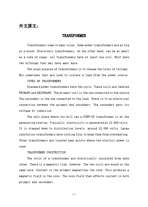
外文原文:TRANSFORMERTransformers come in many sizes. Some power transformers are as big as a house. Electronic transformers, on the other hand, can be as small as a cube of sugar. All transformers have at least one coil. Most have two although they may have many more.The usual purpose of transformers is to change the level of voltage. But sometimes they are used to isolate a load from the power source.TYPES OF TRANSFORMERSStandard power transformers have two coils. These coils are labeled PRIMARY and SECONDARY. The primary coil is the one connected to the source. The secondary is the one connected to the load. There is to no electrical connection between the primary and secondary. The secondary gets its voltage by induction.The only place where you will see a STEP-UP transformer is at the generating station. Typically, electricity is generated at 13,800 volts. It is stepped down to distribution levels, around 15,000 volts. Large substation transformers have cooling fins to keep them from overheating. Other transformers are located near points where the electric power is used.TRANSFORMER CONSTRUCTIONThe coils of a transformer are electrically insulated from each other. There is a magnetic link, however. The two coils are wound on the same core. Current in the primary magnetizes the core. This produces a magnetic field in the core. The core field then affects current in both primary and secondary.There are two main designs for cores:1.The CORE type has the core inside the windings.2.The SHELL type has the core outside.Smaller power transformers are usually of the core type. The very large transformers are of the shell type. There is no difference in their operation, however.Coils are wound with copper wire. The resistance is kept as low as possible keep losses low.IDEALIZED TRANSFORMERSTransformers are very efficient. The losses are often less than 3 percent. This allows us to assume that they are perfect in many computations.Perfect means that the wire has no resistance. It also means that there are no power losses in the core.Further, we assume that there is no flux leakage. That is, all of the magnetic flux links all of the turns on each coil.EXCITATION CURRENTTo get an idea of just how small the losses are, we can take a look at the EXCITATION CURRENT. Assume that nothing is connected to the secondary. If you apply rated voltage to the primary, a small current flows. Typically, this excitation current is less than 3 percent of rated current.Excitation current is made up of two part is in phase with the voltage. This is the current that supplies the power lost in the core. Core losses are due to EDDY CURRENTS and HYSTERESIS.Eddy currents circulating in the core result from induction. The core is, after all, a conductor within a changing magnetic field.Hysteresis loss is caused by the energy used in lining up magneticdomains in the core. The alignment goes on continuously, first in one direction, then in the other.The other part of the excitation current magnetizes the core. It is this magnetizing current that supplies the “shuttle power”. Shuttle power stored in the magnetic field and returned to the source twice each cycle. Magnetizing current is quadrature (90 degrees out of phase) with the applied voltage.1. INTRODUCTIONThe high-voltage transmission was need for the case electrical power is to be provided at considerable distance from a generating station. At some point this high voltage must be reduced, because ultimately is must supply a load. The transformer makes it possible for various parts of a power system to operate at different voltage levels. In this paper we discuss power transformer principles and applications.2. TOW-WINDING TRANSFORMERSA transformer in its simplest form consists of two stationary coils coupled by a mutual magnetic flux. The coils are said to be mutually coupled because they link a common flux.In power applications, laminated steel core transformers (to which this paper is restricted) are used. Transformers are efficient because the rotational losses normally associated with rotating machine are absent, so relatively little power is lost when transforming power from one voltage level to another. Typical efficiencies are in the range 92 to 99%, the higher values applying to the larger power transformers.The current flowing in the coil connected to the ac source is called the primary winding or simply the primary. It sets up the flux φ in thecore, which varies periodically both in magnitude and direction. The flux links the second coil, called the secondary winding or simply secondary. The flux is changing; therefore, it induces a voltage in the secondary by electromagnetic induction in accordance with Lenz’s law. Thus the primary receives its power from the source while the secondary supplies this power to the load. This action is known as transformer action.3. TRANSFORMER PRINCIPLESWhen a sinusoidal voltage Vpis applied to the primary with the secondary open-circuited, there will be no energy transfer. Theimpressed voltage causes a small current Iθto flow in the primary winding. This no-load current has two functions: (1) it produces the magnetic flux in the core, which varies sinusoidally between zero and φm, whereφmis the maximum value of the core flux; and (2) it provides a component to account for the hysteresis and eddy current losses in the core. There combined losses are normally referred to as the core losses.The no-load current Iθis usually few percent of the rated full-load current of the transformer (about 2 to 5%). Since at no-load the primary winding acts as a large reactance due to the iron core, the no-load current will lag the primary voltage by nearly 90º. It is readily seenthat the current component Im = Isinθ, called the magnetizing current,is 90º in phase behind the primary voltage VP. It is this component thatsets up the flux in the core; φ is therefore in phase with Im.The second component, Ie =Isinθ, is in phase with the primaryvoltage. It is the current component that supplies the core losses. The phasor sum of these two components represents the no-load current, orI 0 = Im+ IeIt should be noted that the no-load current is distortes andnonsinusoidal. This is the result of the nonlinear behavior of the core material.If it is assumed that there are no other losses in the transformer, the induced voltage In the primary, E p and that in the secondary, E s canbe shown. Since the magnetic flux set up by the primary winding ,there will be an induced EMF E in the secondary winding in accordance with Faraday’s law, namely, E=NΔφ/Δt. This same flux also links the primary itself, inducing in it an EMF, E p . As discussed earlier, theinduced voltage must lag the flux by 90º, therefore, they are 180º out of phase with the applied voltage. Since no current flows in the secondary winding, E s =V s . The no-load primary current I 0 is small, a few percentof full-load current. Thus the voltage in the primary is small and V p is nearly equal to E p . The primary voltage and the resulting flux aresinusoidal; thus the induced quantities E p and E s vary as a sine function.The average value of the induced voltage given byE avg = turns× change in flux in a given time given time which is Faraday’s law applied to a f inite time interval. It followsthatE avg = N21/(2)m f = 4fNφm which N is the number of turns on the winding. Form ac circuit theory, the effective or root-mean-square (rms) voltage for a sine wave is 1.11 times the average voltage; thusE = 4.44fNφmSince the same flux links with the primary and secondary windings, the voltage per turn in each winding is the same. HenceE p = 4.44fN p φmandE s = 4.44fN s φmwhere E p and Es are the number of turn on the primary and secondarywindings, respectively. The ratio of primary to secondary induced voltage is called the transformation ratio. Denoting this ratio by a, it is seen that a = p sE E = p s N N Assume that the output power of a transformer equals its input power, not a bad sumption in practice considering the high efficiencies. What we really are saying is that we are dealing with an ideal transformer; that is, it has no losses. ThusP m = P outorV p I p × primary PF = V s I s × secondary PFwhere PF is the power factor. For the above-stated assumption it means that the power factor on primary and secondary sides are equal; thereforeV p I p = V s I s from which is obtainedp s V V = p s I I ≌ p sE E ≌ a It shows that as an approximation the terminal voltage ratio equals the turns ratio. The primary and secondary current, on the other hand, are inversely related to the turns ratio. The turns ratio gives a measure of how much the secondary voltage is raised or lowered in relation to the primary voltage. To calculate the voltage regulation, we need more information.The ratio of the terminal voltage varies somewhat depending on the load and its power factor. In practice, the transformation ratio is obtained from the nameplate data, which list the primary and secondary voltage under full-load condition.When the secondary voltage V s is reduced compared to the primaryvoltage, the transformation is said to be a step-down transformer: conversely, if this voltage is raised, it is called a step-up transformer. In a step-down transformer the transformation ratio a is greater than unity (a>1.0), while for a step-up transformer it is smaller than unity (a<1.0). In the event that a=1, the transformer secondary voltage equals the primary voltage. This is a special type of transformer used in instances where electrical isolation is required between the primary and secondary circuit while maintaining the same voltage level. Therefore, this transformer is generally knows as an isolation transformer.As is apparent, it is the magnetic flux in the core that forms the connecting link between primary and secondary circuit. In section 4 it is shown how the primary winding current adjusts itself to the secondary load current when the transformer supplies a load.Looking into the transformer terminals from the source, an impedanceis seen which by definition equals V p / I p . From p s V V = p s I I ≌ p sE E ≌ a , we have V p = aV s and I p = I s /a.In terms of V s and I s the ratio of V p to I p isp p V I = /s s aV I a = 2s sa V I But V s / I s is the load impedance Z L thus we can say thatZ m (primary) = a 2Z LThis equation tells us that when an impedance is connected to the secondary side, it appears from the source as an impedance having a magnitude that is a 2 times its actual value. We say that the load impedance is reflected or referred to the primary. It is this property of transformers that is used in impedance-matching applications.4. TRANSFORMERS UNDER LOADThe primary and secondary voltages shown have similar polarities,as indicated by the “dot-making” convention. The dots near the upperends of the windings have the same meaning as in circuit theory; the marked terminals have the same polarity. Thus when a load is connected to the secondary, the instantaneous load current is in the direction shown. In other words, the polarity markings signify that when positive current enters both windings at the marked terminals, the MMFs of the two windings add.Since the secondary voltage depends on the core flux φ, it mustbe clear that the flux should not change appreciably if Esis to remain essentially constant under normal loading conditions. With the loadconnected, a current Iswill flow in the secondary circuit, because theinduced EMF Eswill act as a voltage source. The secondary currentproduces an MMF Ns Isthat creates a flux. This flux has such a directionthat at any instant in time it opposes the main flux that created it in the first place. Of course, this is Lenz’s law in action. Thus the MMFrepresented by Ns Istends to reduce the core flux φ. This means thatthe flux linking the primary winding reduces and consequently the primaryinduced voltage Ep, This reduction in induced voltage causes a greater difference between the impressed voltage and the counter induced EMF, thereby allowing more current to flow in the primary. The fact thatprimary current Ipincreases means that the two conditions stated earlier are fulfilled: (1) the power input increases to match the power output, and (2) the primary MMF increases to offset the tendency of the secondary MMF to reduce the flux.In general, it will be found that the transformer reacts almost instantaneously to keep the resultant core flux essentially constant.Moreover, the core flux φdrops very slightly between n o load and fullload (about 1 to 3%), a necessary condition if Epis to fall sufficientlyto allow an increase in Ip.On the primary side, Ip’ is the current that flows in the primaryto balance the demagnetizing effect of Is . Its MMF NpIp’ sets up a fluxlinking the primary only. Since the core flux φ0 remains constant. Imust be the same current that energizes the transformer at no load. Theprimary current Ip is therefore the sum of the current Ip’ and I.Because the no-load current is relatively small, it is correct to assume that the primary ampere-turns equal the secondary ampere-turns, since it is under this condition that the core flux is essentially constant. Thus we will assume that Iis negligible, as it is only a small component of the full-load current.When a current flows in the secondary winding, the resulting MMF (Ns Is )creates a separate flux, apart from the flux φ0 produced by I, whichlinks the secondary winding only. This flux does no link with the primary winding and is therefore not a mutual flux.In addition, the load current that flows through the primary winding creates a flux that links with the primary winding only; it is called the primary leakage flux. The secondary- leakage flux gives rise to an induced voltage that is not counter balanced by an equivalent induced voltage in the primary. Similarly, the voltage induced in the primary is not counterbalanced in the secondary winding. Consequently, these two induced voltages behave like voltage drops, generally called leakage reactance voltage drops. Furthermore, each winding has some resistance, which produces a resistive voltage drop. When taken into account, these additional voltage drops would complete the equivalent circuit diagram of a practical transformer. Note that the magnetizing branch is shown in this circuit, which for our purposes will be disregarded. This follows our earlier assumption that the no-load current is assumed negligiblein our calculations. This is further justified in that it is rarelynecessary to predict transformer performance to such accuracies. Sincethe voltage drops are all directly proportional to the load current, it means that at no-load conditions there will be no voltage drops in eitherwinding.The power transformer is a major power system component that permits economical power transmission with high efficiency and lowseries-voltage drops. Since electric power is proportional to theproduct of voltage and current, low current levels (and therefore low I2 losses and low IZ voltage drops) can be maintained for given power Rlevels via high voltages. Power transformers transform ac voltage andcurrent to optimum levels for generation, transmission, distribution,and utilization of electric power.The development in 1885 by William Stanley of a commercially practicaltransformer was what made ac power systems more attractive than dc powersystems. The ac system with a transformer overcame voltage problemsencountered in dc systems with a transformer overcame voltage problemsencountered in dc systems as load levels and transmission distancesincreased. Today’s modern power transformers have nearly 100%efficiency, with ratings up to and beyond 1300 MVA.In this chapter, we review basic transformers theory and developequivalent circuits for practical transformers operating undersinusoidal-steady-state conditions. We look at models of single-phasetwo-winding, three-phase two-winding, and three-phase three-windingtransformers, as well as auto-transformers and regulating transformers.Also, the per-unit system, which simplifies power system analysis byeliminating the ideal transformer winding in transformers equivalentcircuits, is introduced in this chapter and used throughout the remainderof the text.How Electric Utilities Buy Quality When They Buy TransformersBecause transformers are passive devices with few moving parts, it is difficult to evaluate the quality of one over another. But today, when the lifetime cost of transformer losses far exceeds the initial transformer purchase price and a significant percentage of transformer purchases is to replace units that have failed in service, utilities need a mechanism to weigh one manufacturer’s offering against another’s –often well before the transformer is actually built .Power and distribution transformers present entirely different problems to the purchasing engineers charged with evaluating quality. Power transformers are generally custom-built and today they are often very different from any transformers should be evaluated according to a wide range of quality factors, each of which has a different importance or weight, depending on the purchasing utility.In contrast, distribution transformers are purchased in bulk and, provided detailed failure records are kept, the quality can be rather easily determined from computerized statistical programs.LOW LOSSES MEAN HIGH QUALITYOne factor in the engineer’s favor is that high-quality transformers are also low-loss transformers. In a sense, the cost of high quality is automatically paid for in the first few years of transformer life by reduced losses. To this benefit is added the fact that the lifetime of a transformer built today will actually be significantly longer than that of a transformer built only a few years ago.Losses are divided into load and no-load losses and various formulas and/or computer programs are available to evaluate their lifetime impact. When individual utilities plug their cost factors into the formulas, thelifetime impacts they calculate vary widely. For example, the ratio of estimated costs of no-load to load losses can vary by a factor as much as 10 to one. The relative cost of load and no-load losses can also vary from year to year as regulatory pressures push utility management to emphasize different needs.Noise is becoming an increasingly important factor in transformer selection. Again, this factor varies widely from utility to utility. The greatest need for a low-noise transformer is felt by utilities in highly developed areas where substations must be located close to residential neighborhoods.Transformer noise is generated from three sources: (1) the magneto strictive deformation of the core, (2) aerodynamic noise produced by cooling fans, (3) the mechanical and flow noise from the oil-circulating pumps. The radiated core noise, consisting of a 120-Hz tone, is the most difficult to reduce and is also the noise that generates the transformer.Fortunately, improved core-construction techniques and lower-loss core steel both tend to reduction in core noise is needed, it can only be achieved by increasing the cross-sectional area of the core to reduce the flux density. This design change increases the construction cost of the transformer and decreases the core losses. However, a point of diminishing returns is reached at which the cost of increasing core size outweighs the savings in reduced losses.Installation costs are significant because a power transformer must generally be delivered partially disassembled and without oil in the tank. Today, the trend is for the manufacturer to assemble and fill the transformer on site, rather than leave it to the utility. This provides assurance that the transformer is correctly installed and minimizes the cost of lost parts, misunderstanding, etc.Manufacturing facilities provide a key indication of the product quality. Most utilities use plant visits as the first step in their evaluation process. Facility review should include the manufacturer’s quality-assurance program, in-service and test reliability records, contract administration and order support, and technical strength.Coating systems, especially for pad-mount transformers, are becoming increasingly important since the life of the transformer tank may be the limiting factor in transformer life. The problem of evaluating and comparing coating systems on pad-mount transformers from different manufacturers was eliminated with the introduction of ANSI Standard C57.12.28-1988. This is a functional standard that does not dictate to manufacturers now they should coat transformers, but prescribes a series of tests that the coating must withstand to meet the standard. A companion standard, C57.12.31 for poletop transformers, is now under development.Tests prescribed by the standards include: Scratching to bare metal and exposing to salt spray for 1500 hours; cross-hatch scratching to check for adhesion, humidity exposure at 113℃, impact of 160 in.-1b with no paint chipping , oil and ultraviolet resistance, and 3000 cycles of abrasion resistance.In response to this standard, most manufacturers have revamped or rebuilt their painting processes--from surface preparation through application of primers, to finished coating systems. The most advanced painting processes now use electrodeposition methods—either as a dip process or with paint applied as dry power. These processes not only ensure a uniform coating system to every part of the transformer tank out also, because they eliminate traditional solvent-based paints, more easily meet the Clean Air Act Amendments of 1990.Hard evaluation factors are set down in the purchaser’s technicalspecifications, which form the primary document to ensure that all suppliers’products meet a minimum standard. Technical specifications generally include an evaluation formula for no-load and load losses, price, noise level, and delivery date. Technical assistance during installation, warranty assistance, and the extent of warranty are additional hard evaluation factors.Soft factors do not have a precise monetary value, but also may be important in comparing suppliers’ bids. The [following] list suggests soft factors for buyers to include in a transformer-purchase decision. While they do not have a direct dollar value, it is valuable to assign a fixed dollar value or a percentage of bid value to these factors so that they can be used in comparing suppliers’ bids. A well-written specification places all potential suppliers on an equal footing.SOFT FACTORS THAT SHOULD INFLUENCE CHOICE OF SUPPLIERWide choice of designsComputer-aided design proceduresR&D directed at product improvementParticipation in long-term R&D projects through industry groups Clean-room assembly facilitiesAvailability of spare and replacement partsWide range of field servicesApplication assistance/coordinationOngoing communication with usersTony Hartfield, ABB Power T&D Co., Power Transformer Div., St. Louis, Missouri, says it is important to review technical specifications in detail with prospective suppliers before a request for bids is issued. “We attempt to resolve ambiguous terms such as ‘substantial,’ ‘long-lasting,’ or ‘equal-to,’ and replace them with functionalrequirements that clearly define what must be supplied.“Many times, items are added to a specification to prevent recurrence of past problems. These can be counterproductive, particularly if the technology has advanced to a point where the source of the problem has been eliminated.”GOOD IN-SERVICE RECORDS VITALDistribution transformers are purchased in large quantities under very competitive conditions where a unit-price change of a few cents can affect the choice of supplier. As a result, the most sophisticated programs used to guide purchasing policy are based on statistical records of units in service.One example of a systematic failure-analysis program is that conducted by Wisconsin Public Service Corp. (Electrical World, September 1991, p 73). All transformers purchased by the utility since the mid 1980s and all transformer failures are entered into a computerized record-keeping system. Failure rates and equivalent costs are calculated for each manufacturer on a 4-year rolling window. According to Senior Standards Engineer Michael Radke, the system has substantially reduced failure rates, improved communications with transformer vendors, reduced costs, and reduced outages. The system has even helped some manufacturers to reduce failure rates.Georgia Power Co.’s vendor evaluation program has been in place for about 5 years. This program looks at supplier and product separately, judging each according to pre-established criteria. The scores for each criterion are weighted and the over-all score used to calculate a numerical multiplier, which is applied to initial bid price. David McClure, research manager, quality and support, explains that the program involves four departments: engineering, materials, qualityassurance, and procurement. Each department is responsible for a portion of the evaluation and the results from each are entered into a computer program.The evaluation involves objective and subjective factors. Compliance, for example, can be measured objectively, but customer service must be evaluated subjectively. Even so, reviewers follow a well-defined procedure to determine scores for each factor. This approach ensures that ratings are applied consistently to each vendor.Public Service Co. of Colorado (PSC) uses a numerical multiplier that is applied to the bid price. The multiplier incorporates several factors—including historical failure rate, delivery, and quality. Of these factors, historical failure rate is by far the most important, accounting for more than half of the multiplier penalty. For example, the average multiplier for pole-mounted transformers adds 6.3%, of which failure rate accounts for 4.9%; the average multiplier for single-phase pad-mount transformers adds 5.3%, of which failure rate accounts for 3.6%.Failure rate is calculated using a computer program supplied by General Electric Co., Transformer Business Dept, Hickory, North Carolina. It is based on failures of transformers purchased in the last 10 years. The cost of failure includes the cost of a replacement unit and the costs of changeout and downtime.A delivery penalty is calculated by PSC, based on the difference in weeks between promised and actual delivery dates. Significantly, this penalty is calculated equally for early as for late delivery. Early delivery is considered disruptive. John Ainscough, senior engineer, automation analysis and research, reports that his department is planning to modify this factor to encourage both short lead-times andon-time delivery. Currently, the delivery factor does not incorporate the supplier’s manufacturing cycle time.PSC’ s quality factor is based on the percentage of an order that must be repaired or returned to the manufacturer; the accuracy with which products conform to the original specifications, including losses and impedance; and the number of days required to resolve complaints and warranty claims. Responsiveness to complaints is considered a soft evaluation factor and the number of days needed to resolve a complaint is a way of quantifying this factor. The utility is exploring ways to quantify other soft factors in the evaluation process.According to Ainscough, the rating system in use at PSC seems to be effective for consistently selecting high-quality vendors and screening out those that offer low bids at the expense of product quality.Another software program designed to help purchasers select the best available distribution transformer is a Lotus-compatible worksheet for evaluating distribution transformers offered by ABB Power T&D Co. The worksheet adjusts criteria for reliability, quality, delivery/availability, and support. The lower the value factor, the lower is the effective first cost of the transformer. To the adjusted first cost is added the cost of losses, yielding a life-cycle cost for the transformer.Suggested weightings, based on surveys of utilities, are provided for each critertion, but users can easily modify these criteria in light of their own experience and needs. According to ABB’s Dorman Whitley, this ensures that the worksheet does not favor any one manufacturer. Users can also incorporate soft criteria (such as supplier’s long-term commitment to the industry, or level of investment in R&D).LOSSES INFLUENCE RELIABILITY。
Transformer变压器外文文献翻译
Transformer变压器One of the most valuable apparatus in electric power system is the transformer, for it enables us to utilize different voltage levels across the system for the most economical value. Generation of power at the synchronous machine level is normally at a relatively low voltage,which is most desirable economically.Stepping up of this generated voltage to high voltage,extra-high voltage or even to ultra-high voltage is done through power transformers to suit the power transmission requirement to minimize losses and increase the transmission capacity of the lines.This transmission voltage level is then stepped down in many stages for distribution and utilization purposes.电力系统中的最有价值之一是器具的变压器,它使我们能够利用不同电压等级,整个系统的最经济的值。
通常在较低功率在同步计算机级别的一代是voltage,which,是最理想的economically.Stepping 高voltage,extra 高电压该生成电压或甚至超高电压通过以适应电力传输的要求,尽量减少损失的电力变压器和增加lines.This 输电电压等级的输电量然后走在很多阶段的分布和利用的目的最有价值的一个装置在电力系统变压器,因为它使我们能够利用不同系统电压水平在最经济的价值。
电力专业术语英汉翻译
10月8日《水利水电工程技术术语标准》(二)由WESTBANK根据中华人民共和国水利部能源部联合发布的《水利水电工程技术术语标准》整理,鉴于篇幅空间限制,删除了定义部分和重复部分床面形态 Bed form床沙质(造床质) bed material load垂线观测坐标仪(垂线观测仪) coordinatograph for plummet observation垂线平均流速 mean velocity at a vertical垂直度 perpendicularity垂直度盘指标差(指标差,竖盘指标差) index error of vertical circle垂直升船机 vertical ship lift垂直收缩系数 vena-contracta coefficient垂直位移工作点 operative mark of vertical displacement垂直位移观测(沉陷观测,沉降观测) vertical displacement observation垂直位移基点 datum mark of vertical displacement磁法勘探 magnetic prospecting磁方位角 magnetic azimuth磁极 fieid pole磁子午线 magnetic meridian次固结(次压缩) secondary consolidation(secondary compression)次固结沉降 secondary consolidation settlement次生曲流 submeander次生盐碱化 secondary salinization次要建筑物 secondary structure凑合节 adjuster of steel pipe粗骨料 coarse aggregate粗碎 primary crushing粗制螺栓 bolt,rough bolt错缝 staggered joint搭接 lap joint达西渗流定律Darcy′s law of seepage大坝变形观测 dam deformation observation大坝水泥 dam cement大暴雨 large rainstorm大潮(朔望潮) spring tide大地构造 geotectonics大地控制点(大地点) geodetic control point大地水准面 geoid大地原点(大地基准点) geodetic datum大气窗口 atmospheric window大气折光差 atmospheric refraction error大体积混凝土 mass concrete大头坝 massive-head dam (massive-buttress dam)大修理费 overhauling cost代表性露点 representative dew point带喉管的圆筒式调压室 throttled surge chamber带舌瓣闸门 gate with flap带速饱和变流器差动保护 longitudinal differential protection employing quickly-saturable transformer带状间作 strip cropping带状淤积 belt deposit贷款偿还年限 pay back period of loan单层布置 single storey layout单调节调速器 single-regulation governor单回线 single-circuit line单机调节 independent regulation单级单吸悬臂式离心泵 single-stageend-suction centrifugal pump单级双吸式离心泵 single-stagedouble-suction centrifugal pump单极高压直流系统 monopolar/unipolar HVDC system单价合同(固定单价合同) unit-price contract单价和总价混合合同 lump-sum and unit-price combined contract单列布置 single row layout单母线接线 single-bus connection单曲拱坝 single curvature arch dam单位弹性抗力系数 coefficient of unit elastic resistance单位电能投资 cost per kilowatt-hour单位工程 unit project单位耗药量 powder factor单位容量投资(单位千瓦投资) cost per kilowatt单位水力矩 unit hydraulic torque单位水推力 unithydraulic thrust单位线(单位过程线) unit hydrograph单位线(时段单位线) unit hydrograph单位转速[流量][出力] unit speed[discharge][power]单吸式离心泵 single-suction pump单相变压器 single-phase transformer单相重合闸 one-phase ARC单向变形 one directional deformation单向波 one-direction wave单斜岩层 monocline单因子试验 experiment of single factor单元接线(发电机—变压器组接线) generator-transformer unit connection弹簧常数 spring constant弹性 elasticity弹性极限 limit of elasticity弹性抗力系数 coefficient of elastic resistance弹性模量(弹性系数,杨氏模数) modulus of elasticity弹性屈曲 elastic buckling弹性释水系数(弹性给水度) elastic storavity弹性支承 elastic support当地加速度(时变加速度) local acceleration挡潮闸(防潮闸) tide barrage挡水建筑物 water retaining structure挡水面板 water retaining deck挡水墙 head wall挡土墙 retaining wall导爆索(传爆索) primacord (detonatin fuse)导洞掘进法 heading and cut method导航建筑物(导航架) guide structure (approachtrestle) 导火索 safety fuse导流 River diversion导流堤取水 intake with diversion dike导流方案 diversion scheme导流方式(导流方法) diversion procedure导流孔(洞)封堵 plugging of the diversion opening导流流量标准(导流标准) diversion discharge frequency 导流时段 diversion period导流隧洞 diversion tunnel导沙槽 sand-guide channel导沙坎(拦沙坎,挡沙坎) sand-guide sill导水机构 gate operating mechanism导水系数 coefficient of transmissivity导水锥 hydrocone导线测量 traverse survey导线点 traverse point导线网 traverse network导线网平差 adjustment of traverse network导向坡度 guide slope导向装置 guiding device导叶分布圆 gate circle,wicket gate circle导叶高度 guide vane height导叶开口 guide vane opening导叶限位块 gate stop导轴承 guide bearing导轴瓦间隙 guide bearing clearance倒锤线观测(倒锤法) inverse plumb line observation倒虹吸管 inverted siphon稻田适宜水深 suitable water depth in paddy field灯泡式水轮发电机 bulb hydraulic generator灯泡式水轮机 bulb turbine等高耕作(横坡耕作) contour tillage等高截流 contour interception等高距(等高线间隔) contour interval等高线 contour等径流深图 runoff isopleth map等流时线 isochrone等密图 contour diagram等面积定则 equal-area criterion等容粒径 volume equivalent diameter等水位线图 water table contour map等速流 homogeneous flow等效网络 equivalent network等压面 equi-pressure surface等雨量线图 isohyetal map等值线图 isoline map低坝 low dam低电压保护 under voltage protection低电压闭锁(起动)过电流保护 under voltage-started over current protection 低流态混凝土 low-slump concrete低频起动 low frequency starting低型布置 low-type layout低压(低电压) low voltage (L.V.)低压配电屏 low voltage distribution panel/board低压配电装置 Low voltage switchgear installation低压配电装置 low voltage switchgear installation低扬程泵站 low-head pumping station堤 dike (embankment,levee)堤后式泵房 pump house at levee-toe堤身式泵房 water retaining pump house滴灌 drip irrigation滴灌系统 system of drip irrigation底环 bottom ring底槛 embedded sill (ground sill)底孔导流 bottom outlet diversion底栏栅式取水 bottom-grating intake底流消能(水跃消能) energy dissipation by hydraulic jump底枢 bottom pintle底缘 bottom edge抵偿年限 payment period抵偿年限法 payment period method地表径流 surface runoff地基沉降 ground settlement地基处理 Foundation treatment地基处理 Treatment of foundation地基稳定分析 Stability analysis of foundation地脚螺栓 foundation bolt地壳 earth crust地壳形变观测(大坝库区地壳形变观测) observation of earth crust deformation 地幔 earth mantle地貌 geomorphy地貌综合 cartographic generalization of relief地面分辨力 ground resolution地面灌溉系统 Surface irrigation system地面立体摄影测量 terrestrial stereo photogrammetry地面露点 dew point at earth surface地面排水系统 Surface drainage system地球弯曲差 error due to curvature of earth地球物理勘探(物探) geophysical prospection地图 map地图编绘 Map Compilation地图编绘(原图编绘) map compilation地图编绘与制印 Map Compilation and Reproduction地图分幅 Sheet line system地图复照 map photography地图清绘 map fair drawing地图投影 map projection地图投影变换 map projection transfromation地图投影变形 distortion of map projection地图图号(图号) map numbering地图图式(图式) cartographic symbol地图印刷 map printing地图整饰 map appearance地图制版 map printing plate making地图制印 map reproduction地图制印与仪器 Map reproduction and instrument地物 planimetric feature地物和地貌的表示 representation of planimetric feature and geomorphy地下暗管灌溉 irrigation by buried pipes地下工程施工 Under ground works construction地下浸润灌溉 subsurface irrigation by groundwater地下径流 groundwater runoff地下轮廓线 underground configuration地下埋管 underground penstock地下排水 subsurface drainage地下排水系统 Subsurface drainage system地下热水 hot groundwater地下式厂房 underground power house地下式水电站 underground hydroelectric station地下水侧向补给 recharge by ground water地下水超量开采 excessive mining of ground water地下水动态 ground water regime地下水降深 drawdown of groundwater地下水开采 Ground water mining地下水矿化度 mineralization of ground water地下水利用量 ground water supplement to the crop root zone地下水临界深度 critical depth of ground water地下水平衡(地下水均衡) ground water balance地下水人工补给(人工回灌) artificial recharge of ground water地下水水文地质特性 Hydro geological characteristics of groundwater 地下水下降漏斗 depression cone of ground water地下水越层补给 recharge through weak permeable layer地下水资源 Ground water resources地下水资源开发利用 Development of ground water resources地形 landform地形测量 topographic survey地形图 topographic map地性线(地貌结构线,地貌特征线) orographic character line地震 earthquake地震动水压力 earthquake hydrodynamic pressure地震惯性力 earthquake inertia force地震勘探 seismic prospecting地震烈度 earthquake intensity地震前兆 premonitory symptom地震区划 seismic zoning地震水波 water wave by earthquake地震震级 earthquake magnitude地质编录 geological record地质点 geological observation point地质点测量 geololgical point survey地质构造 geologic structure地质基础 Basicgeology地质勘探 geological exploration地质雷达 geological radar地质力学 geomechanics地质剖面 geological section地质素描 geological sketch典型暴雨 typical rainstorm点法测量 point wise点荷载强度 point load strength点位中误差 mean square error of position点污染源 point-source of pollution点雨量 point precipitation(point rainfall)电测探法 electrical sounding电磁波测距误差 error in electromagnetic wave distance measurement电磁波测距仪 Electromagnetic wave distance measuring instrument(EDMI)电磁波测距仪(物理测距仪) electromagnetic wave distance measuring instrument(EDMI)电动发电机组 motor-generator set电动机 Motor电动机的额定转矩 rated load torque of motor电动机的起动转矩 starting torque of motor电动潜水泵 submersible motor pump电法勘探 electrical prospecting电机 Electrical machine电价 electricity price电抗器 Reactor电抗器 reactor (shunt reactor)电缆夹层 cable interlayer电雷管 electric blasting cap电力不足时间期望值 loss of load expectation (LOLE)电力弹性系数(电力超前系统) elastic coefficient of electric energy电力电缆 power cable电力负荷 Electric power load电力负荷(电力负载) electric power load电力负荷图 electric load diagram电力工程二次部分 Electrotechnical Secondary Circuit电力工程一次部分 Electrotechnical Primary Circuit电力系统 Electrical power system电力系统的集中控制 centralized control of power system电力系统调度 Power system dispatch电力系统计算 Calculation of electric power system电力系统可靠性 Reliability of electric power system电力系统容量 Installed capacity of electric system电力系统运行 Operation of electric power system电力系统状态估计 state estimation in power system电力线载波通信 power line carrier communication电量不足期望值 expected energy not served (EENS)电流差动保护 current differential protection电流互感器 current transformer (CT)电流互感器的精确等级 accurate degree of current transformer电流密度 current density电流平衡保护 current balance protection电路图 circuit diagram电气缓冲单元 electric damper电气设备选择 Electric equipment selection电气液压式调速器 electro-hydraulic governor电气制动 braking resistance (BR)电气主接线 main electrical connection电容式电压互感器 capacitor voltage transformer电视测井 television logging电压变化率保护 voltage change rate protection电压调整率 voltage regulationrate电压互感器 potential transformer (PT) (voltage transformer)电压互感器的精确等级 accurate degree of potential transformer电压降 voltage drop (potential drop)电压控制母线(PV母线) voltage control busbar电压偏移 voltage deviation电液转换器(电液伺服阀) electro-hydraulic transducer,electro-hydraulic servo-valve电液转换器失灵 maladjustment of electro-hydraulic transducer电源 Power source电站气蚀系数 plant cavitation factor电制动 electromagnetic braking电子速测仪(全站式电子速测仪,自动电子速测仪) electronic tacheometer电子印像机 electronic printer电阻率剖面法(电剖面法) resistivity profiling凋萎系数 wilting coefficient, withering coefficient吊车轨道 crane rail吊车梁 crane runway girder吊耳 hoist eye (hook eye)吊杆 hanger (gate stem)吊罐 bucket吊距 centre distance between two hoist eyes调度端 control end (dispatching end)调度通信 dispatching communication调洪库容 flood control storage调绘像片 identified photograph调节流量 regulated flow调节年度 regulation year调节容积 adjustable volume调节系数 regulation coefficient调节周期 period of regulation调速器结构与部件 Components of governor调速器静特性试验 static characteristic test of governor调速器类型 Types of governor调速器失灵 maladjustment of governor调速系统 governing system调速系统静态特性(永态转差系数图) static characteristics of governing system (speed droop graph)调相容量 compensator capacity (condensator capacity)调相压水 bear on water for phase modulation (bear on water for condenser operation) 调蓄容积 storage capacity调压阀(空放阀) pressure regulator调压阀关闭时间 closing time for pressure regulator调压阀开启时间 opening time for pressure regulator调压阀滞后时间 dead time for pressure regulator调压井 surge shaft调压室 surge chamber调压塔 surge tank跌水 drop叠梁闸门 stoplog丁坝 spur dike (groin)顶盖 top cover (head cover)顶盖排水 head cover drainage顶管法 pipe jacking method顶枢 upper gudgeon (top pintle)定床河流模型(定床河工模型) fixed bed model定点定面关系 precipitation relationship between fixed point and fixed area定电流控制(定电流调节) constant current control/regulation定电压控制(定电压调节) constant voltage control定功率控制 constant power control定量评价 quantitative evaluation定轮闸门 fixed roller gate (fixed wheel gate)定期保养 periodical maintenance, regular maintenance定倾半径 metacentric radius定倾中心 metacenter定时限电流保护 definite time-lag current protection定向爆破 directional throw blasting定向取心 directional coring定性评价 qualitative evaluation定裕度角控制(定裕度角调节) constant margin angle control定子 stator定子短路时间常数 stator short-circuit time constant定子接地保护 earthing fault protection for generator stator定子匝间短路保护 stator inter-turn fault protection冬、雨季施工增加费 additional cost in winter-rainy season动床河流模型(动床河工模型) movable bed model动点动面关系(暴雨中心点面关系) precipitation relationship between center point and variable area动断触点(常闭接点) break contact (normally-closed contact)动合触点(常开接点) make contact (normally-open contact)动荷载 dynamic load动静弹模比 ratio of static-dynamic moduli动库容 dynamical storage动力触探试验 dynamic cone penetration test动力弹性模量 dynamic modulus of elasticity动力控制箱 power control box动力配电箱 power distributing box动力系数 dynamic factor动力相似 dynamic similarity动力粘滞系数 dynamic viscosity coefficient动力装备率(动力装备系数) powered equipment rate动量改正系数 momentum coefficient动量损失厚度 momentum loss thickness动能改正系数 kinetic energy coefficient动平床 moving flat bed动平衡 dynamic balancing动水压强 hydrodynamic pressure动态经济分析 dynamic economic analysis动态稳定 dynamic-state stability动态相似(运动相似) kinematic similarity冻结基面 stationary datum冻胀力 frost heave pressure冻胀量 frost-heave capacity洞蚀 cave and hole erosion洞室爆破 coyote blasting陡槽(泄槽) chute陡槽式溢洪道 chute spillway陡坡 chute陡坡 steep slope独立坐标系 independent coordinate system渡槽 aqueduct (flume)渡槽导流 aqueduct flume diversion端电池 end cell端面承压应力 bearing stress端子(接线端子,引出端子) terminal端子接线图 terminal connection diagram短管 short pipe短路 short circuit短路比 short-circuit ratio (SCR)短路电流 short circuit current短路电流非周期分量 aperiodic component of short circuit current 短路电流周期分量 periodic component of short circuit current短路计算 Short circuit calculation短路容量 short-circuit capacity短路校验计算 short-circuit check calculation短期水文预报 short date hydrologic forecasting断层 fault断层擦痕 slicken side断层角砾岩 fault breccia断层泥 fault gouge断层破碎带 shatterred fault zone断层破碎带处理 treatment of fault and fracture zone断层破碎带处理 treatment of fault-fracture zone断层上盘 hanging wall断层下盘 heading wall断口 fracture断裂韧性 toughness of fracture断流围堰导流(拦断河床导流,全断面导流) full river by-pass diversion断路器 circuit breaker断路器失灵保护(后备接线保护) breaker failure protection断面比力 specific force断面比能 specific energy断面测量 section survey断面模型 sectional model断面平均流速 average velocity of cros ssection断面平均流速 mean velocity at across-section(over all mean velocity)断水保护 water supply cut-off protection堆焊 pad welding堆积阶地 construction alter race堆石 rock filling堆石坝 rock fill dam对称电压 symmetric voltage对接 butt joint对流层散射通信 tropospheric scatter communication对数螺线形拱坝 logarithmic spiral arch dam对外交通 site access盾构法 shielding method多波段扫描仪(多光谱扫描仪) multi band scanner多端高压直流输电系统 multi-terminal HVDC transmission system多阀单元 multiplevalve unit多级泵 multi-stage pump多级泵站 multistage pumping station多级船闸 multi-stage lock (flight locks)多年调节 over year regulation(carry over regulation)多年平均年发电量 average annual energy output多年平均年径流量 mean annual runoff多首制取水 multi-head water intake多线船闸 multi-line lock (multiple lock)多相流 multi-phase flow多油式断路器 bulk oil circuit breaker额定变比 rated transformation ratio额定电流 rated current额定电压 rated voltage额定动稳定电流(额定极限通过电流) rated dynamic current (rated limit through-current)额定工况 rated condition额定工况(满载工况) rated condition额定关合电流 rated making current额定开断电流 rated breaking current额定频率 rated frequency额定容量 rated capacity额定水头 rated head额定油压 rated oil pressure额定值 rated value额定值 rated value (rating)额定转速 rated speed二[三]段式电流保护 two[three]-step current protection二倍照准差互差(2c互差,2c较差) discrepancy between twice collimation errors二次电流[电压] secondary current[voltage]二次回路 secondary circuit二次接线图 secondary connection diagram二次筛分(最终筛分) finish screening二端高压直流输电系统 two-terminal HVDC transimission system二期冷却 second stage cooling二维流(二元流) two-dimensional flow发包设计 bid design发电电动机 generator-motor发电机-变压器组保护 protection for generator-transformer unit发电机[电力变压器、调相机、电动机、母线、电抗器]保护 protection of synchronous generator [power transformer,condenser,motor,bus-bar,reactor]。
中文翻译S13M 油浸式电力变压器
S13M 油浸式电力变压器电压等级(kV)额定容量(kVA)密封式结构性能水平代号三相油浸变压器产品简介◇S13型是在S11型系列配电变压器基础上开发的产品,具有低损耗、低噪音、抗短路能力强、抗冲击性好及良好的经济运行性等特点。
◇正常环境使用条件:海拔不超过1000m。
环境温度最高+40℃,最低-25℃。
◇供工农业配电动力和照明使用。
◇本系列产品与S11型变压器相比,空载损耗降低约30%以上。
◇铁芯采用优质高导磁硅钢片,全斜多级接缝叠积式。
◇器身多点定位,全部紧固件用防松螺母,能承受振动、颠簸和倾斜运输的考验,满足不吊心的要求。
◇高压绕组全部采用多层圆筒式结构,改善了绕组的冲击分布;绕组采用不浸漆工艺,用紧缩带绑扎,提高绕组的机械强度。
◇油箱可采用片式散热器或波纹油箱配储油柜,加装带油封的吸湿器。
执行标准◇GB1094.1~2-1996 电力变压器◇GB1094.3,5-2003 电力变压器◇GB/T6451-2008 三相油浸式电力变压器技术参数和要求6kV、10kV级13型无励磁调压配电变压器空载损耗和负载损耗额定容量(kVA)空载损耗(W)负载损耗(W)注:表中斜线上方的负载损耗值用于Dyn11或yzn11联结组,斜线下方的负载损耗值适用于Yyn0联结组。
注:1、有关更大容量的10kV级配电变压器的技术参数、外形尺寸及重量数据请垂询我公司。
2、可根据用户需求提供各种电压组合、短路阻抗、联结方式的变压器。
广西华南电气有限公司主要生产、销售高低压成套开关设备、控制设备、直流电源设备、高压开关、组合式变电站、自动化设备、高强度密封母线槽、电缆桥架、电线电缆等输配电设备和电力工程配套安装服务。
以上产品均已获得国家强制性“CCC”认证,并通过ISO9001:2000质量管理体系认证,ISO14001:2004环境管理体系认证,OHSAS1800:2007职业健康安全体系认证。
公司本着“立足质量,面向世界,着眼未来”的企业理念,采用国际一流的管理手段,依照国内外成功企业的生产、管理、销售、服务一条龙的运作方式,秉承“质量兴企,科技兴业”的发展模式和“顾客第一,服务至上”的原则,大力实施“以质量创市场,以品牌求发展,以科技促进步的品牌战略”,采取新的决策,树立新的优势,抓紧机遇,乘势前进,以质量为中心,以顾客为关注焦点,把改革与创新作为企业发展的核心推动力,不断深化现代企业制度改革,提高产品的科技含量和售后服务质量,与社会各界同仁和广大用户携手努力,精诚合作,开拓创新,以更新、更强的“GXHN 桂电”品牌形象书写辉宏的篇章!。
翻译_风电词汇
FIFO 先进先出
Switch cabinet 开关盒
Slip 滑动
Slewing 定位
air brake 空气制动
cut-in speed 切入风速
nominal wind speed 额定风速
cut-out speed 切出风速
stop wind speed 停止风速
revolution 旋转
anemometer 测风仪
vane 风向标
planet/parallel axles 行星/平行轴
microprocessor 微处理器
译各翻译员尽量在翻译前预览这些词汇、在译中不确定的词汇优先参考本词汇表。
风电项目常用英语词汇
tubular tower 塔筒式塔架
lattice tower 桁架式塔架
nacelle 机舱
dB (A), decibel (A) scale 分贝
delta connection Δ连接
density of air 空气密度
direct grid connection 直接并网
circumferential 圆柱的
longitudinal 经度的
proportionate 成比例的
zinc 锌,涂锌于
efficiency 效率
energy balance 能量平衡
extreme load 极端负荷
fatigue load 疲劳负荷
jib 臂
stator 定子
stall 失速
upwind 上风向
downwind 下风向
speed up effect 加速
电气英语翻译专业词汇
电气工程词汇voltage电压diode二极管current电流potentiometer电位器resistance电阻step-uptransformer升压变压器reactance电抗powersystem电力系统,电网impedance阻抗transmissionline输电线conductance电导breaker断路器inductance电感relay继电器inductor电感器demodulator解调器capacitance电容radiator散热器capacitive电容性的,电容的ventilation通风,换气,通风装置shuntcapacitor并联电容器alternatingrelay交流继电器shunt并联integratedcircuitamplifier集成电路放大器series串联transistoramplifier晶体管放大器seriescircuit串联电路terminal端子parallelcircuit并联电路amplifier/magnifier放大器conductor导线cablen电缆v架设电缆voltmeter电压表fuse保险丝熔断器ammeter电流表interface接口arc电弧amplitude振幅幅度波幅chargen电荷v充电,带电,起电digitalsignal数字信号dischargev放电coupling耦合bridge电桥intermittent周期的valve电子管dislocation错位deenergize断路malfunction故障dielectric不导电的/绝缘的medium介质generator发电机screen屏蔽motor电动机dampen阻尼audion三极管socket插孔groundplane接地层alternatingcurrent交流电流three-phasen三相inverting反相potentialdifference电位差outofphase异相activeelement有源元件self-inductor自感idealindependentsource理想独立电源mutual-inductor互感watthourmeter感应线圈ampere安培frequencychanger变频器coulomb库仑controlswitch控制开关joule焦耳selectorswitch选择开关resistor电阻器currenttransformer电流互感器charger充电器powertransformer电力变压器semiconductor半导体phasevoltage相电压absolutevalue绝对值constantvoltagesource恒定电压源operatingsupplyvoltage电源工作电压专业词汇Isolator刀闸(隔离开关)定串联电容补偿Susceptance电纳voltagestability电压稳定regulator稳压器anglestability功角稳定admittance导纳installedcapacity装机容量rectifier整流器transformersubstation变电站busbar母线degreeofcompensation补偿度analogsignal模拟信号linedropcompensation(LDC)线路补偿asynchronism异步器synchronization同步circuittheorems电路定理armature电枢superpositiontheorem叠加定理attenuate衰减substitutiontheorem替代定理steam-turbine-drivengenerator气轮发thevenin-NortonTheorem戴维宁定理电机electromagnetism电磁;电磁学turbinegenerator涡轮发电机low-frequencyamplifier低频放大器magneticflux磁通量low-frequencybypass低频旁路oscilloscope示波器voltagedistortion交流电压校准器oscillator震荡器SingleChipMicroprocessor(SCM)单片机multimeter万用表alternatingcurrent(AC)交流/交流电overlay叠加效果adjustablepressureconveyor调压输送ratedpower额定功率机poweramplifier功率放大器allowableloadimpedance允许的负载阻activevoltage有效电压抗voltagetocurrentconverter电压电流closedloopcontrol闭环控制变换器closedloopvoltagegain闭环电压增益transformersubstation变电站closed-loopgain死循环增益regulation调节clutch离合器/联轴器degreeofcompensation补偿度commutator/rectifier整流器highvoltageshuntreactor高抗cutoffvoltage临界电压reactivepowercompensation无功补偿cut-involtage闭合电压three-columntransformer三绕组变压器dielectricadj.不导电的/绝缘的double-columntransformer双绕组变压器dielectricpuncture击穿power-factor功率因数electricaldurability电寿命(万次)voltagegrade电压等级electromagneticresonance电磁感应no-loadcurrent空载电流electromotiveforce电动力/电动势impedance阻抗positivecharge正电荷positivesequenceimpedance正序阻抗negativecharge负电荷negativesequenceimpedance负序阻抗AutomaticGenerationControl(AGC)自动zerosequenceimpedance零序阻抗发电控制susceptance电纳PowerSystemStabilizator(PSS)电力系stator定子统稳定器highvoltage高压polyphase多相(的) fixedseriescapacitorcompensation固iron-loss铁损armaturecircuit电枢电路interface接口dynamicresponse动态响应demodulator解调器timeinvariantadj.时不变的balanceindicator交流平衡指示器self-inductor自感currentcalibrator交流电流校准器mutual-inductor互感resistancebox交流电阻箱polarity极性voltagedistortion交流电压校准器ventilation通风,换气,通风装置standardresistor交流标准电阻器low-frequencybypass低频旁路directcurrent(DC)直流电powerpool联合电力系统;联合电网eddycurrent涡流electromagnetism电磁;电磁学corridor通路core/shellforme铁心式/壳式inducedcurrent感生电流potentialdifference电位差laminatedcore叠片铁芯dualin-linepackages双列直插式组件left-handrule左手定则automaticcontrolsystem自动控制系统volt-amperecharacteristics伏安特性torquemotor力矩电动机simulationanalysis仿真分析amplifierusingdiscrete分离元件放大onemachine-infinitybussystem单机器无穷大系统potentiometer电位器ElectricalMachinery电机学voltage-currentcharacteristic伏安特AutomaticControlTheory自动控制理论性ElectrotechnicsPrincipleofCircuits topology拓扑电工学termocouple热电偶ElectricalDriveandControl电力传动与exitation激发;激励;干扰控制air-gap气隙brownout节约用电polyphasen.多相adj.多相的cathode阴板、负极breakdowntorque失步转矩cationexchanger阳离子交换器locked-rotortorque止转转矩circuitbreaker电路断路器nominalfrequency额定频率circuitdiagram电路图subtransmission二次输电coaxialcable同轴电缆hydro-generation水力发电coolingtower冷却塔feeder馈线;馈电电路intermediaterelay中间继电器thermalunit热力机组jumper跳线、跨接activepowerbalance有功功率平衡lightningarrestor避雷器load-frequencycontrol(LFC)负荷频率installedcapacity装机容量控制instrumentpanel仪表盘sychronouscondenser同步调相机tap-changingtransformer可调分接头变压器tapcoil跳闸线圈magneticaircircuitbreaker磁吹断路器automaticgenerationcontrol(AGC)自动发电控制circuitboard电路板i nstantaneouspower瞬时功率lossofexcitation励磁损失manualreject手动切换overheadline架空线plantloadfactor电厂负荷因数potentialtransformer电压互感器overspeedtrip超速跳闸pyod热电偶safepotential安全电压shield屏蔽层WORD格式singlebladeswitch单刀开关starconnectedsystem星形连接制"Y"staticstorage静态存储器stationcapacity发电厂容量step-downtransformer降压变压器substation变电站、子站subtransmission二次输电thermalpowerplant热力发电厂thumbrule安培右手定则trip跳闸、断开starconnectedsystem星形连接制"Y"A/Cadaptor电源适配器analogtodigital模拟/数字转换acinducedpolarizationinstrument交流激电仪adjustablepressureconveyor调压输送机allowableloadimpedance允许的负载阻抗chargeneutrality电中性区ChargeTerminationVoltage允电端电压/允电端接电压circuitdiagram电路板circuitswitching电路交换closed-loopvoltagegain死循环电压增益connectors插接器constantvoltagemodulation稳压调节currentattenuation电流减衰装置CurrentbyPhase(AMP)每相电流currentlimitativerange电流限制范围cutoffvoltage临界电压cut-involtage闭合电压DischargeTerminationVoltage放电端电压dropoutvoltage跌落电压eddycurrent涡电流electormagneticbrakingsytem电磁制动系统electricdipole电偶极子electricshielding电屏蔽FrequencyHopping跳频input-outputcontrolsystem(IOCS)输入输出控制系统offsetvoltage失调电压。
电气主要名词翻译
电气专业主要名词翻译一、发电、输电1.发电机power generator2.柴油发电机组diesel generators3.储油间oil storage room4.控制柜control cabinet5.供电公司power supply company(s)6.供电局electricity supplier(s)二、高压配电high-voltage distribution1.高压进线柜high-voltage incoming cabinet/high-voltage inlet wiring carbinet2.高压电容补偿柜high-voltage capacitor compensate cabinet3.高压馈线柜high-voltage feeder cabinet4.高压开关柜、开关站high-voltage switch cabinet、high-voltage switchboard house5.高压柜型号the model of high voltage board6.高压柜编号high voltage board number7.高压柜尺寸the dimension of high voltage board8.配电总容量main distribution capacity9.真空断路器vacuum circuit breaker10.弹簧操作机构(直流操作)spring operation mechanism11.避雷器(lightning)arrester12.高供高量(高压供电、高压计量)high-voltage supply、high pressure measurement13.电气联锁electric lever interlocking14.直流屏direct current panels15.计量柜metering cabinet16.继电器relay三、变电所、变电站、开关站substation、switchboard house/switchyard1.变压器transformer2.低压配电柜、变压器柜、进线柜、无功补偿柜low-voltage distributors、3.配电箱(配电盘)switch box(electricity panel)4.配电线路distribution line5.塑壳断路器moulded case circuit breaker6.电容器、电抗器capacitor、reactor7.电流互感器current transformer8.电压互感器voltage transformer9.隔离开关isolating switch/disconnecting switch10.变电所低压主接线图low-voltage main wiring diagram of substation11.母线bus bar12.电缆cable13.导线electrical wire14.控制线control line15.工作电流operating current16.备用电源secondary power supplies17.功率因数补偿compensation of power factor18.变频站frequency changing station19.一次primary20.二次secondary四、动力1.双电源切换箱switch box for double power supply2.电力配电箱power switch box3.照明配电箱lightning switch box4.设备控制箱equipment control box5.电表箱meter box6.总等电位联结端子箱general equipotential bonding terminal box7.局部等电位联结端子箱local equal potential connection terminal box8.排烟风机smoke exhaust fan9.正压送风机pressurized forced draught fan10.排风机exhaust fan11.交流电动机alternating-current motor12.直流电动机direct-current motor13.电梯elevators14.自动扶梯escalator15.电梯控制箱elevators control box五、照明1.工作照明work lighting2.备用照明back up lighting3.应急照明emergency lighting4.疏散照明evacuation lighting5.蓄电池storage battery6.荧光灯fluorescent lamp7.白炽灯incandescent lamp8.节能灯energy-saving lamp9.吸顶灯ceiling lamp10.防水防尘灯waterproof and dustproof lamp11.密闭灯closed lamp12.壁灯bracket lamp13.灯座socket/lamp holder14.应急照明灯emergency lighting fixtures15.疏散指示灯evacuation lighting fixtures16.安全出口标志灯safety exit light17.换气扇ventilating fan18.双控开关double-control switch19.双联开关double connection plane switch/flashing at two points20.单联开关single connection switch21.三联开关tripe connection switch22.密闭开关enclosed switch23.防爆开关flame-proof switch24.控制按钮control button25.安全型两极加三极插座safe socket with two poles and three poles26.安全型两极加三极密闭插座safe closed socket with two poles and three poles27.带开关三极插座three poles socket with switch28.带开关两极插座two poles socket with switch29.带开关两极加三极插座two poles and three poles socket with switch30.安全型三极插座safe three poles socket31.眩光glare六、专有名词1.有功功率effective power2.无功功率reactive power3.视在功率apparent power4.线电压line voltage5.线电流line current6.相电压phase voltage7.相电流phase current8.额定电压rated voltage9.电阻resistance10.光通量luminous flux11.照度、照明、亮度illuminance、lighting、luminance12.接地系统earth network13.接地电阻grounding resistance14.接地线earthing conductor15.密闭母线槽、电缆桥架、金属线槽、金属管、塑料管closed bus bar groove、cable tray、metallic channel、metal pipe、plastic pipe16.耐火电缆(导线)、矿物绝缘电缆fire-proof cable(wire)、mineral insulated cable17.阻燃电缆(导线fire-retardant cable(wire)18.绝缘insulation19.绝缘子insulator20.接线图connection diagram21.电涌保护器surge protector22.漏电保护leakage protective23.避雷带(针)、避雷器mesh(lighting rods)、lightning arrester24.功率因数power factor25.蓄电池storage battery26.有效值、平均值、最大值、最小值effective value、mean value、maximum value、minimumvalue27.瞬时值instantaneous value28.频率frequency29.电流互感器current transformer30.电压互感器voltage transformer31.电容器capacitor32.电抗器reactor33.过电流保护overcurrent protection34.过电压保护overvoltage protection35.过载保护overload protection36.零序保护zero sequence protection37.机械联锁mechanical interlocking38.电气联锁electeic lever interlocking39.过流速断保护instantaneous over-current relay40.照度计算illuminance calculation41.负荷计算calculation method42.压降计算calculation of pressure drop43.防雷计算lightning protection calculation。
- 1、下载文档前请自行甄别文档内容的完整性,平台不提供额外的编辑、内容补充、找答案等附加服务。
- 2、"仅部分预览"的文档,不可在线预览部分如存在完整性等问题,可反馈申请退款(可完整预览的文档不适用该条件!)。
- 3、如文档侵犯您的权益,请联系客服反馈,我们会尽快为您处理(人工客服工作时间:9:00-18:30)。
附录A 译文变压器1. 介绍要从远端发电厂送出电能,必须应用高压输电。
因为最终的负荷,在一些点高电压必须降低。
变压器能使电力系统各个部分运行在电压不同的等级。
本文我们讨论的原则和电力变压器的应用。
2. 双绕组变压器变压器的最简单形式包括两个磁通相互耦合的固定线圈。
两个线圈之所以相互耦合,是因为它们连接着共同的磁通。
在电力应用中,使用层式铁芯变压器(本文中提到的)。
变压器是高效率的,因为它没有旋转损失,因此在电压等级转换的过程中,能量损失比较少。
典型的效率范围在92到99%,上限值适用于大功率变压器。
从交流电源流入电流的一侧被称为变压器的一次侧绕组或者是原边。
它在铁圈中建立了磁通φ,它的幅值和方向都会发生周期性的变化。
磁通连接的第二个绕组被称为变压器的二次侧绕组或者是副边。
磁通是变化的;因此依据楞次定律,电磁感应在二次侧产生了电压。
变压器在原边接收电能的同时也在向副边所带的负荷输送电能。
这就是变压器的作用。
3. 变压器的工作原理当二次侧电路开路是,即使原边被施以正弦电压V p,也是没有能量转移的。
外加电压在一次侧绕组中产生一个小电流Iθ。
这个空载电流有两项功能:(1)在铁芯中产生电磁通,该磁通在零和 φm之间做正弦变化,φm是铁芯磁通的最大值;(2)它的一个分量说明了铁芯中的涡流和磁滞损耗。
这两种相关的损耗被称为铁芯损耗。
变压器空载电流Iθ一般大约只有满载电流的2%—5%。
因为在空载时,原边绕组中的铁芯相当于一个很大的电抗,空载电流的相位大约将滞后于原边电压相位90º。
显然可见电流分量I m= I0sinθ0,被称做励磁电流,它在相位上滞后于原边电压V P 90º。
就是这个分量在铁芯中建立了磁通;因此磁通φ与I m 同相。
第二个分量I e =I 0sin θ0,与原边电压同相。
这个电流分量向铁芯提供用于损耗的电流。
两个相量的分量和代表空载电流,即I 0 = I m + I e应注意的是空载电流是畸变和非正弦形的。
这种情况是非线性铁芯材料造成的。
如果假定变压器中没有其他的电能损耗一次侧的感应电动势E p 和二次侧的感应电压E s 可以表示出来。
因为一次侧绕组中的磁通会通过二次绕组,依据法拉第电磁感应定律,二次侧绕组中将产生一个电动势E ,即E=N Δφ/Δt 。
相同的磁通会通过原边自身,产生一个电动势E p 。
正如前文中讨论到的,所产生的电压必定滞后于磁通90º,因此,它于施加的电压有180º的相位差。
因为没有电流流过二次侧绕组,E s =V s 。
一次侧空载电流很小,仅为满载电流的百分之几。
因此原边电压很小,并且V p 的值近乎等于E p 。
原边的电压和它产生的磁通波形是正弦形的;因此产生电动势E p 和E s 的值是做正弦变化的。
产生电压的平均值如下E avg = turns×给定时间内磁通变化量给定时间即是法拉第定律在瞬时时间里的应用。
它遵循E avg = N 21/(2)m f = 4fN φm其中N 是指线圈的匝数。
从交流电原理可知,有效值是一个正弦波,其值为平均电压的1.11倍;因此E = 4.44fN φm因为一次侧绕组和二次侧绕组的磁通相等,所以绕组中每匝的电压也相同。
因此E p = 4.44fN p φm并且E s = 4.44fN s φm其中N p 和E s 是一次侧绕组和二次侧绕组的匝数。
一次侧和二次侧电压增长的比率称做变比。
用字母a 来表示这个比率,如下式a = ps E E = p s N N假设变压器输出电能等于其输入电能——这个假设适用于高效率的变压器。
实际上我们是考虑一台理想状态下的变压器;这意味着它没有任何损耗。
因此P m = P out或者V p I p × primary PF = V s I s × secondary PF这里PF 代表功率因素。
在上面公式中一次侧和二次侧的功率因素是相等的;因此V p I p = V s I s从上式我们可以得知ps V V = p s I I ≌ p s E E ≌ a它表明端电压比等于匝数比,换句话说,一次侧和二次侧电流比与匝数比成反比。
匝数比可以衡量二次侧电压相对于一次恻电压是升高或者是降低。
为了计算电压,我们需要更多数据。
终端电压的比率变化有些根据负载和它的功率因素。
实际上, 变比从标识牌数据获得, 列出在满载情况下原边和副边电压。
当副边电压V s 相对于原边电压减小时,这个变压器就叫做降压变压器。
如果这个电压是升高的,它就是一个升压变压器。
在一个降压变压器中传输变比a 远大于1(a>1.0),同样的,一个升压变压器的变比小于1(a<1.0)。
当a=1时,变压器的二次侧电压就等于起一次侧电压。
这是一种特殊类型的变压器,可被应用于当一次侧和二次侧需要相互绝缘以维持相同的电压等级的状况下。
因此,我们把这种类型的变压器称为绝缘型变压器。
显然,铁芯中的电磁通形成了连接原边和副边的回路。
在第四部分我们会了解到当变压器带负荷运行时一次侧绕组电流是如何随着二次侧负荷电流变化而变化的。
从电源侧来看变压器,其阻抗可认为等于V p / I p 。
从等式 ps V V = p s I I ≌ p s E E ≌a 中我们可知V p = aV s并且I p = I s /a 。
根据V s 和I s ,可得V p 和I p 的比例是pp V I = /s s aV I a = 2s s a V I但是V s / I s 负荷阻抗Z L ,因此我们可以这样表示Z m (primary) = a 2Z L这个等式表明二次侧连接的阻抗折算到电源侧,其值为原来的a 2倍。
我们把这种折算方式称为负载阻抗向一次侧的折算。
这个公式应用于变压器的阻抗匹配。
4. 有载情况下的变压器一次侧电压和二次侧电压有着相同的极性,一般习惯上用点记号表示。
如果点号同在线圈的上端,就意味着它们的极性相同。
因此当二次侧连接着一个负载时,在瞬间就有一个负荷电流沿着这个方向产生。
换句话说,极性的标注可以表明当电流流过两侧的线圈时,线圈中的磁动势会增加。
因为二次侧电压的大小取决于铁芯磁通大小φ0,所以很显然当正常情况下负载电势E s 没有变化时,二次侧电压也不会有明显的变化。
当变压器带负荷运行时,将有电流I s 流过二次侧,因为E s 产生的感应电动势相当于一个电压源。
二次侧电流产生的磁动势N s I s 会产生一个励磁。
这个磁通的方向在任何一个时刻都和主磁通反向。
当然,这是楞次定律的体现。
因此,N s I s 所产生的磁动势会使主磁通φ0减小。
这意味着一次侧线圈中的磁通减少,因而它的电压E p 将会增大。
感应电压的减小将使外施电压和感应电动势之间的差值更大,它将使初级线圈中流过更大的电流。
初级线圈中的电流I p 的增大,意味着前面所说明的两个条件都满足:(1)输出功率将随着输出功率的增加而增加(2)初级线圈中的磁动势将增加,以此来抵消二次侧中的磁动势减小磁通的趋势。
总的来说,变压器为了保持磁通是常数,对磁通变化的响应是瞬时的。
更重要的是,在空载和满载时,主磁通φ0的降落是很少的(一般在)1至3%。
其需要的条件是E 降落很多来使电流I p 增加。
在一次侧,电流I p ’在一次侧流过以平衡I s 产生的影响。
它的磁动势N p I p ’只停留在一次侧。
因为铁芯的磁通φ0保持不变,变压器空载时空载电流I0必定会为其提供能量。
故一次侧电流I p是电流I p’与I0’的和。
因为空载电流相对较小,那么一次侧的安匝数与二次侧的安匝数相等的假设是成立的。
因为在这种状况下铁芯的磁通是恒定的。
因此我们仍旧可以认定空载电流I0相对于满载电流是极其小的。
当一个电流流过二次侧绕组,它的磁动势(N s I s)将产生一个磁通,于空载电流I0产生的磁通φ0不同,它只停留在二次侧绕组中。
因为这个磁通不流过一次侧绕组,所以它不是一个公共磁通。
另外,流过一次侧绕组的负载电流只在一次侧绕组中产生磁通,这个磁通被称为一次侧的漏磁。
二次侧漏磁将使电压增大以保持两侧电压的平衡。
一次侧漏磁也一样。
因此,这两个增大的电压具有电压降的性质,总称为漏电抗电压降。
另外,两侧绕组同样具有阻抗,这也将产生一个电阻压降。
把这些附加的电压降也考虑在内,这样一个实际的变压器的等值电路图就完成了。
由于分支励磁体现在电流里,为了分析我们可以将它忽略。
这就符我们前面计算中可以忽略空载电流的假设。
这证明了它对我们分析变压器时所产生的影响微乎其微。
因为电压降与负载电流成比例关系,这就意味着空载情况下一次侧和二次侧绕组的电压降都为零。
附录B 外文原文TRANSFORMER1. INTRODUCTIONThe high-voltage transmission was need for the case electrical power is to be provided at considerable distance from a generating station. At some point this high voltage must be reduced, because ultimately is must supply a load. The transformer makes it possible for various parts of a power system to operate at different voltage levels. In this paper we discuss power transformer principles and applications.2. TOW-WINDING TRANSFORMERSA transformer in its simplest form consists of two stationary coils coupled by a mutual magnetic flux. The coils are said to be mutually coupled because they link a common flux.In power applications, laminated steel core transformers (to which this paper is restricted) are used. Transformers are efficient because the rotational losses normally associated with rotating machine are absent, so relatively little power is lost when transforming power from one voltage level to another. Typical efficiencies are in the range 92 to 99%, the higher values applying to the larger power transformers.The current flowing in the coil connected to the ac source is called the primary winding or simply the primary. It sets up the flux φ in the core, which varies periodically both in magnitude and direction. The flux links the second coil, called the secondary winding or simply secondary. The flux is changing; therefore, it induces a voltage in the secondary by electromagnetic induction in accordance with Lenz’s law. Thus the primary receives its power from the source while the secondary supplies this power to the load. This action is known as transformer action.3. TRANSFORMER PRINCIPLESWhen a sinusoidal voltage V p is applied to the primary with the secondary open-circuited, there will be no energy transfer. The impressed voltage causes a small current Iθ to flow in the primary winding. This no-load current has two functions: (1) it produces the magnetic flux in the core, which varies sinusoidally between zero and φm, where φm is the maximum value of the core flux; and (2) it provides a component to account for the hysteresis and eddy current losses in the core. There combined losses are normally referred to as the core losses.The no-load current Iθis usually few percent of the rated full-load current of the transformer (about 2 to 5%). Since at no-load the primary winding acts as a large reactance due to the iron core, the no-load current will lag the primary voltage by nearly 90º. It is readily seen that the current component I m= I0sinθ0, called the magnetizing current, is 90ºin phase behind the primary voltage V P. It is this component that sets up the flux in the core; φ is therefore in phase with I m.The second component, I e=I0sinθ0, is in phase with the primary voltage. It is the current component that supplies the core losses. The phasor sum of these two components represents the no-load current, orI0 = I m+ I eIt should be noted that the no-load current is distortes and nonsinusoidal. This is the result of the nonlinear behavior of the core material.If it is assumed that there are no other losses in the transformer, the induced voltage In the primary , E p and that in the secondary , E s can be shown. Since the magnetic flux set up by the primary winding ,there will be an induced EMF E in the secondary winding in accordance with Faraday’s law, namely , E=NΔφ/Δt. This same flux also links the primary itself, inducing in it an EMF, E p . As discussed earlier, the induced voltage must lag the flux by 90º, therefore, they are 180º out of phase with the applied voltage. Since no current flows in the secondary winding, E s =V s . The no-load primary current I 0 is small, a few percent of full-load current. Thus the voltage in the primary is small and V p is nearly equal to E p . The primary voltage and the resulting flux are sinusoidal; thus the induced quantities E p and E s vary as a sine function. The average value of the induced voltage given byE avg = turns× change in flux in a given timegiven timewhich is Faraday’s law applied to a finite time interval. It follows thatE avg = N 21/(2)mf = 4fNφmwhich N is the number of turns on the winding. Form ac circuit theory , the effective or root-mean-square (rms) voltage for a sine wave is 1.11 times the average voltage; thusE = 4.44fNφmSince the same flux links with the primary and secondary windings, the voltage per turn in each winding is the same. HenceE p = 4.44fN p φmandE s = 4.44fN s φmwhere E p and Es are the number of turn on the primary and secondary windings, respectively . The ratio of primary to secondary induced voltage is called the transformation ratio. Denoting this ratio by a, it is seen thata = ps E E = p s N NAssume that the output power of a transformer equals its input power, not a bad sumption in practice considering the high efficiencies. What we really are saying is that we are dealing with an ideal transformer; that is, it has no losses. ThusP m = P outorV p I p × primary PF = V s I s × secondary PFwhere PF is the power factor. For the above-stated assumption it means that the power factor on primary and secondary sides are equal; thereforeV p I p = V s I s from which is obtainedps V V = p s I I ≌ p s E E ≌ aIt shows that as an approximation the terminal voltage ratio equals the turns ratio. The primary and secondary current, on the other hand, are inversely related to the turns ratio. The turns ratio gives a measure of how much the secondary voltage is raised or lowered in relation to the primary voltage. To calculate the voltage regulation, we need more information.The ratio of the terminal voltage varies somewhat depending on the load and its power factor. In practice, the transformation ratio is obtained from the nameplate data, which list the primary and secondary voltage under full-load condition.When the secondary voltage V s is reduced compared to the primary voltage, the transformation is said to be a step-down transformer: conversely, if this voltage is raised, it is called a step-up transformer. In a step-down transformer the transformation ratio a is greater than unity (a>1.0), while for a step-up transformer it is smaller than unity (a<1.0). In the event that a=1, the transformer secondary voltage equals the primary voltage. This is a special type of transformer used in instances where electrical isolation is required between the primary and secondary circuit while maintaining the same voltage level. Therefore, this transformer is generally knows as an isolation transformer.As is apparent, it is the magnetic flux in the core that forms the connecting link between primary and secondary circuit. In section 4 it is shown how the primary winding current adjusts itself to the secondary load current when the transformer supplies a load.Looking into the transformer terminals from the source, an impedance is seen which by definition equals V p / I p . From ps V V = p s I I ≌ p s E E ≌ a , we have V p = aV sand I p = I s /a.In terms of V s and I s the ratio of V p to I p ispp V I = /s s aV I a = 2s s a V IBut V s / I s is the load impedance Z L thus we can say thatZ m (primary) = a 2Z LThis equation tells us that when an impedance is connected to the secondary side, it appears from the source as an impedance having a magnitude that is a 2 times its actual value. We say that the load impedance is reflected or referred to the primary . It is this property of transformers that is used in impedance-matching applications.4. TRANSFORMERS UNDER LOADThe primary and secondary voltages shown have similar polarities, as indicated by the “dot -making” convention. The dots near the upper ends of t he windings have the same meaning as in circuit theory; the marked terminals have the same polarity . Thus when a load is connected to the secondary , the instantaneous load current is in the direction shown. In other words, the polarity markings signify that when positive current enters both windings at the marked terminals, the MMFs of the two windings add.Since the secondary voltage depends on the core flux φ0, it must be clear that the flux should not change appreciably if E s is to remain essentially constant under normal loading conditions. With the load connected, a current I s will flow in the secondary circuit, because the induced EMF E s will act as a voltage source. The secondary current produces an MMF N s I s that creates a flux. This flux has such a direction that at any instant in time it opposes the main flux that created it in the firstplace. Of course, this is Lenz’s law in action. Thus the MMF represented by N s I s tends to reduce the core flux φ0. This means that the flux linking the primary winding reduces and consequently the primary induced voltage E p, This reduction in induced voltage causes a greater difference between the impressed voltage and the counter induced EMF, thereby allowing more current to flow in the primary. The fact that primary current I p increases means that the two conditions stated earlier are fulfilled: (1) the power input increases to match the power output, and (2) the primary MMF increases to offset the tendency of the secondary MMF to reduce the flux.In general, it will be found that the transformer reacts almost instantaneously to keep the resultant core flux essentially constant. Moreover, the core flux φ0 drops very slightly between n o load and full load (about 1 to 3%), a necessary condition if E p is to fall sufficiently to allow an increase in I p.On the primary side, I p’is the current that flows in the primary to balance the demagnetizing effect of I s. Its MMF N p I p’sets up a flux linking the primary only. Since the core flux φ0 remains constant. I0 must be the same current that energizes the transformer at no load. The primary current I p is therefore the sum of the current I p’and I0.Because the no-load current is relatively small, it is correct to assume that the primary ampere-turns equal the secondary ampere-turns, since it is under this condition that the core flux is essentially constant. Thus we will assume that I0is negligible, as it is only a small component of the full-load current.When a current flows in the secondary winding, the resulting MMF (N s I s) creates a separate flux, apart from the flux φ0produced by I0, which links the secondary winding only. This flux does no link with the primary winding and is therefore not a mutual flux.In addition, the load current that flows through the primary winding creates a flux that links with the primary winding only; it is called the primary leakage flux. The secondary- leakage flux gives rise to an induced voltage that is not counter balanced by an equivalent induced voltage in the primary. Similarly, the volta ge induced in the primary is not counterbalanced in the secondary winding. Consequently,these two induced voltages behave like voltage drops, generally called leakage reactance voltage drops. Furthermore, each winding has some resistance, which produces a resistive voltage drop. When taken into account, these additional voltage drops would complete the equivalent circuit diagram of a practical transformer. Note that the magnetizing branch is shown in this circuit, which for our purposes will be disregarded. This follows our earlier assumption that the no-load current is assumed negligible in our calculations. This is further justified in that it is rarely necessary to predict transformer performance to such accuracies. Since the voltage drops are all directly proportional to the load current, it means that at no-load conditions there will be no voltage drops in either winding.。