变压器-外文翻译
变压器英译词汇表

变压器有关名词术语英译词汇表A GLOSSARY FOR ENGLISHTRANSLATION OF TRANSFORMERTERMINOLLGYⅠ、基础词汇Voltage combination (of a transformer) 1(变压器的)电压组合2额定电压.Rated voltage3额定电流Rated current4额定容量Rated power5额定电压比Rated voltage ratioNo-load current(exciting current) 6空载电流(激磁电流)7空载损耗No-load loss8负载损耗Load loss9附加损耗Additional losses10杂散损耗Stray losses11阻抗电压Impedance voltage12电阻电压Resistance voltage13电抗电压Reactance voltage14电压调整率Voltage regulation15相位差Phase displacement16零序阻抗Zero-sequence impedance17频率:工频Frequency ,power-frequency中频Medium frequency高频High frequency18震荡频率Oscillating frequency19谐振频率Resonance frequency20自振频率Natural frequency of vibration21频率响应Frequency response22绝缘强度Dielectric strength ,insulation strength 23主绝缘Main insulation24纵绝缘Longitudinal insulation25介电常数Dielectric constant26油-纸绝缘系统Oil-paper insulation system27绝缘击穿Insulation breakdown28沿面放电(爬电)Creeping discharge29放电Discharge30局部放电Partial discharge31破坏性放电Disruptive discharge32局部放电起始电压Partial discharge inception voltage33局部放电终止电压Partial discharge extinction voltage34过电压Overvoltage35短时过电压Short time overvoltage36暂态过电压Transient overvoltage37操作过电压Switching overvoltage38大气过电压Atmospheric covervoltage39额定耐受电压Rated withstand voltage40短时工频耐受电压Short-duration power-frequencywithstand voltage41额定雷电(操作)冲击耐受电压Rated lightning (switching)impulse withstand voltage42屏蔽Shielding43静电屏蔽Electrostatic shielding44磁屏蔽Magnetic shielding45标准大气条件Standard atmospheric condition46视在电荷Apparent charge47全波雷电冲击Full wave lightning impulse48截波雷电冲击Chopped wave lightning impulse49冲击伏秒特性Voltage time characteristics of impulse 50爬电距离Creepage distance51体积电阻Volume resistance52截断时间Time to chopping53波前时间,视在波前时间Time to crest, virtual front time 54半峰值时间Time to half value of crest55峰值Peak value(crest value)56有效值Root-mean-square value 57标么值Per unit value58标称值Nominal value59导电率Admittance60电导Conductance, conductivity61介质损耗率Dielectric loss62介损角的正切值Loss tangent63电晕放电Corona discharge64闪络Flashover65内(外)绝缘External (internal )insulation 66绝缘电阻Insulation resistance67绝缘电阻吸收比Absorption ratio of insulation resistance(R60/R15)68避雷器Surge arrestor69避雷器的残压Residual (discharge )voltage of an arrestor70绝缘材料耐温等级Temperature class of insulation (A,B,F, H)71感应耐压试验Induced overvoltage withstand test72(突发)短路试验Short –circuit test73互感器的负荷Burden of an instrument transformer74额定负荷(互感器)Rated burden (of an instrument transformer) 75标准级次Accuracy class76电流(电压)误差Current (voltage)error77相角差(互感器)Phase displacement (instrument transformer)78复合误差Composite error79暂态特性(误差)Transient characteristics(error)80额定短时热电流Rated short thermal current81额定连续热电流Rated continuous thermal current82额定动稳态电流Rated dynamic current83额定仪表保安电流Rated instrument security current84二次极限感应电势(保安因数)Secondary limiting e.m.f. (security factor)85额定标准极限的一次电流Rated accuracy limit primarycurrent86误差补偿Error compensation87额定电压因数Rated voltage factor 88标准限值因数Accuracy limit factorCartesian coordinate 89笛卡尔坐标(直角坐标)90极坐标Polar coordinate91横坐标abscissa (X-axis)92纵坐标Ordinate(Y-axis)93复数,实数部分/虚数部分Complex number(a+jb),real component imaginary component94正(负)数Positive(negative)number95小数Decimal96四舍五入Round off97分数,分子/分母Fraction ,numerator/denominator 98假分数Improper fraction99钝(锐)角Obtuse(acute)angle100补角Supplementary angle101余角Complement angle102平行Parallel103垂直Perpendicular104乘方Involution105开方Evolution,extraction of root106n的5次方Involve n to the fifth power;5thpower of n107幂Exponent,exponential108微分Differential,differentiation109积分Integrate, integration110成正比(反比)Proportional (inverselyproportional) to.....111概率Probability112归纳法Inductive method113外推Extrapolation (method)114插入法Interpolation (method)115最大似然法Maximum likelihood (method)116图解法Graphic method117有限元法Finite element method118模拟法Simulation method119方波响应Step respone120迭加电荷Superimposed charge121电位梯度Potential gradient122杂散电容Stray capacitance123超声定位Ultrasonic location (orientation) 124无损探伤Non-distrucitve flaw detection 125红外线扫描Infrared scanning126计算机辅助设计Computer aided design127计算机辅助设计及制造Computer aided design and manufactruing ( CADAM )128计算机辅助试验Computer aided tese(CAT)129最大(最小)Maximun (minimum)130近似于Approximate (approx.)131每分钟转数Revolution per minute (rpm)132速度Speed , velocity133加速度Acceleration134重力加速度(水平加速度)Gravitational acceleration135地震(地震烈度)Seism, earthquake (earthquakeintensity)136数量(件数)Quantity (pieces)137部门Department (dept.)138缩写Abbreviation139(以下简称为***)(Hereinafter referred as *****) 140参见***See ***** , vide ****常用单位(包括缩写) Unis commomly used (including abbriviations)141米,分米,厘米,毫米Meter,decimeter , centimeter, millimeter142公里Kilometer143英里,海里Mile, knot144码,寸Yard, inch145磅,磅/平方时Pound(lb.) pound per square inch(psi)146尺Foot147英制热量单位British thermal unit (BTU)148马力Horsepower149压强Intensity of pressure150帕施卡,千帕,兆帕Pascal (Pa), kpa, mpa151托Torr ( = 1mmhg)152粘度,帕斯卡秒Viscosity , Pascal·second153泊,厘泊Poise , centipois, 1P = 1dyne·sec/cm2154焦耳Joule155千瓦时Kilowatt-hour156特斯拉Tesla(T)157高斯Gauss158奥斯特Oersted(0e)159库仑,微库仑Coulomb,pico-coulomb160牛顿,达因Newton,dyne161摄氏度,开尔文Celsius(centigrade),kelvin162法拉,皮可法拉Farad,pico-farad163升,立方分米,立方厘米Liter,cubic decimeter,cubic centimeter164加仑Gallon165桶(石油)Barrel (petroleum)1barrel=163.65liter166标准国际单位制Standard international unit167厘米-克-秒单位制CGS unit168磁通密度Flux density169电流密度Current density170安匝数Number of ampere –turns171轴向(径向)漏磁通Axial (radial )leakage flux172热点(最热点)Hot(hotest) spot173局部过热Local overheat174涡流损耗Eddy current loss175磁滞损耗Hysteresis loss二、产品结构(产品类型及主要组件、零件)Construction of product(Types and mian component parts)(1)典型产品图解Graphic expressions of typical product1变压器铁心Transformer core(magnetic circuit) 2变压器线圈Transformer winding3线圈端部绝缘End insulation of winding4上部夹件Upper clamping5下部夹件Lower clamping6分接引线Tapping leads7引线支架Supporting frame for leads8高压套管均压球Equipotential shielding for HVbushing9高压引线High-voltage leads10低压引线Low-voltage leads11线圈压紧螺栓Winding compressing bolt12器身定位装置Positioning divice for active-part 13垫脚Foot-pad14小车支架及滚轮Bogie frame and wheel15油箱Tank16箱底Tank bottom17箱盖及箱沿Tank cover and tank rim18垫脚垫块Suppoting block for foot-pad19联管接头(法兰)Tube connetor (connecting flange) 20油箱直立加强铁Vertical stiffening channel of tankwall21油样活门Oil asmping valve22放油活门Oil draining valve23管式散热器Tubular radiator24放油塞Oil draining plug25放气塞Air exhausting plug26风扇支架Supporting frame for fan motors 27风扇及电机Fan and motor28风扇接线盒Connecting box for fan motors29储油柜联管Elbow joint for conservator30气体继电器Gas relay31储油柜Conservator32油位指示计Oil-level indicator33有载开关用储油柜Conservator for OLTC34有载开关用气体继电器Gas relay for OLTC35联管Tube connector36名牌Rating plate37温度计Thermometer38指示仪表柜Cabinet panel for indicatinginstruments39风扇控制柜Cabinet panel for fan motor control 40压力释放阀Pressure-relief valve41主排气导管(导气管)Main gas-conduit42分支导气管Branching gas-filter43滤油接口(蝶阀)Tube connector for oil-filter(butterfly valve)44温度计座Thermometer socket45储油柜支架Supporting frame for conservator 46高压0相套管HV bushing phase 0(neutral)47高压套管HV bushing48低压套管LV bushing19有载分接开关On-load tap-changer(OLTC)50有载开关操动机构Operating mechanism of OLTC51垂直传动轴Vertical driving shaft52水平传动轴Horizontal driving shaft53伞齿轮盒Bevel gear box54防雨罩及联轴节Drip-proof cap and coupling55联轴节Coupling56高压套管储油柜Conservator for HV bushing57相间隔板Interphase insulating barrier58吊拌Lifting lug59安装轨道Installation rail60相序标志牌Designation mark of phasesequence61接地螺栓Earthing bolt(2)各类产品名称及类型1电力变压器Power transformer2有载调压电力变压器Power transformer with OLTC(off-circuit tap-changer)3配电变压器Distrivution transformer4自耦变压器Atuotransformer5联络变压器Interconnecting transformer6升压变压器(降压)Step-up(step-down) transformer7发电机变压器Generator transformer8电站用变压器Substation transformer9变流变压器(换流变压器)Converter transformer10分裂变压器Transformer with split winding11厂用变压器Power plant transformer12单相变压器Single-phase transformer13三相变压器Three-phase transformer14油浸式变压器Oil-immersed transformer15浸难燃油变压器Noninflammable medium impregnated transformer 16干式变压器Dry type transformer17塑料浇注变压器Cast resin(resin moulded)transformer18H级绝缘变压器Transformer with H class insulation19气体绝缘变压器Gas insulated transformer20单相变压器组成的三相组合Three-phase banks with separate single-phase transformers21电炉变压器Furnace transformer22整流变压器Rectifier transformer23列车牵引变压器Traction(locomotive)transformer 24矿用变压器Mining transformer25防爆变压器Flame-proof transformer26隔离变压器Isolation transformer27试验变压器Testing transformer28灯丝变压器Filament transformer29电焊变压器Welding transformer30钎焊变压器Brazing transformer31船用变压器Marine tasnsformer32起动自耦变压器Starting autotransformer33串及式试验变压器Cascade testing transformer34三线圈变压器Three-winding transformer35增压变压器(串联变压器)Booster(series)transformer 36移动式变压器Movable substation37成套变电站Complete substation38全自动保护单相变压器Complete silf-protected single-phase transformer(CSP)39电流互感器Current transformer(CT)40电压互感器Voltage transformer(VT)41母线式电流互感器Bus –type current transformer42瓷箱式电流互感器Porcelain type current transformer 43套管式电流互感器Bushing current transformer44电容式电流互感器Capacitor type current transformer45倒立式电流互感器Reverse type current transformer 46塑料浇注式互感器Cast tesin current transformer47电容式电压互感器Capaitor type voltage transformer 48接地电压互感器Earthed voltage transformer19组合式互感器Combined instrument transformer 50移圈调压器Moving-coil voltage regulator51自耦调压器Autoformer regulator52接触调压器Variac53感应调压器Induction voltage regulator54磁饱和调压器Magnetic saturation voltageregulator55电抗器Reactor56串联电抗器Series reactor57并联电抗器Shunt reactor58铁心电抗器Iron core reactor59空心电抗器Air core reactor60水泥电抗器Concrete (cement)reactor61三相接地电抗器Rhree-phase neutral reactor62起动电抗器Starting reactor63平波电抗器Smothing reactor64平衡电抗器Interphase reactor65消弧电抗器(线圈)Arc-suppression reactor66阻波器(线圈)Wave trap coil67镇流器Ballast68饱和电抗器Saturable reactor69密闭式,包封式Sealed(enclosed )type70芯式Core type71壳式Shell type72户外(户内)式,柱上式Outdoor (indoor,pole mounting)type73移动式(列车式)Movable (trailer mounted)type74自然冷却(吹风冷却)Natural cooling (air blast cooling) 75强油风冷(水冷)Forced oil forced air cooling(watercooling)76油导向冷却Directed forced oil circulation cooling77油导向吹风冷却Directed forced oil circulation forced aircooling78恒磁通调压Constant flux voltage variation(C.F.V.V.) 79变磁通调压Variable flux volatge variation(V.F.V.V.) 80混合调压Combined voltage variation(Cb.V.V.)81油浸自冷Oil –immersed natural cooling(ONAN) 82油浸风冷Oil-immersed forced air cooling(ONAF) 83油浸强迫油循环风冷Oil-immersed forced oil circulationforced air cooling(OFAF)84油浸强油导向风冷Oil-immersed forced-directed oilcirculation forced air cooling(ODAF)(3)铁心core1铁心片Core lamination2一叠铁心 A lamination stack3铁心叠积图Lamination drawing (diagram)445斜拉缝45 mitred joint5铁心油道(气道)Oil-duct(air ventilating duct)of core6阶梯接缝Stepped lap joint7对接铁心Butt joint core8卷铁心Wound core9渐开线铁心Evolute core10空气隙Air gap11铁心拉板Tensile plate of core limb12铁心柱Core limb(leg)13轭(上轭,下轭)Yoke(upper yoke,lower yoke)14旁轭Side yoke15环氧绑扎带Epoxy –bonded bandage16轭拉带Yoke tendile belt17上轭顶梁(侧梁)Top jointing beam of upper yoke(sidebeam)18上夹件(下夹件)Upper yoke clamping (lower yokecalmping)19夹件腹板(肢板)Web(limb)of yoke calmping20夹件加强铁Stiffenting plate of calmping21压线圈的压钉Winding compressing bolt22压钉螺母Nut for compressing bolt23弹簧压钉(油缸压钉)Compressing bolt with spring (hydraulic damper)24线圈支撑架(板)Winding supporter(plate)25垫脚Foot pad26定位孔Positioning hole27带螺母的定位柱Positioning stud28拉螺杆Tensile rod29夹件夹紧螺杆Yoke clamping bolt30铁心接地片Core earthing strip31铁心地屏(旁轭地屏)Earthing screen of core (side yoke)32窗口高度(中心距M。
电子电气专业外文翻译--变压器
外文原文:TRANSFORMERTransformers come in many sizes. Some power transformers are as big as a house. Electronic transformers, on the other hand, can be as small as a cube of sugar. All transformers have at least one coil. Most have two although they may have many more.The usual purpose of transformers is to change the level of voltage. But sometimes they are used to isolate a load from the power source.TYPES OF TRANSFORMERSStandard power transformers have two coils. These coils are labeled PRIMARY and SECONDARY. The primary coil is the one connected to the source. The secondary is the one connected to the load. There is to no electrical connection between the primary and secondary. The secondary gets its voltage by induction.The only place where you will see a STEP-UP transformer is at the generating station. Typically, electricity is generated at 13,800 volts. It is stepped down to distribution levels, around 15,000 volts. Large substation transformers have cooling fins to keep them from overheating. Other transformers are located near points where the electric power is used.TRANSFORMER CONSTRUCTIONThe coils of a transformer are electrically insulated from each other. There is a magnetic link, however. The two coils are wound on the same core. Current in the primary magnetizes the core. This produces a magnetic field in the core. The core field then affects current in both primary and secondary.There are two main designs for cores:1.The CORE type has the core inside the windings.2.The SHELL type has the core outside.Smaller power transformers are usually of the core type. The very large transformers are of the shell type. There is no difference in their operation, however.Coils are wound with copper wire. The resistance is kept as low as possible keep losses low.IDEALIZED TRANSFORMERSTransformers are very efficient. The losses are often less than 3 percent. This allows us to assume that they are perfect in many computations.Perfect means that the wire has no resistance. It also means that there are no power losses in the core.Further, we assume that there is no flux leakage. That is, all of the magnetic flux links all of the turns on each coil.EXCITATION CURRENTTo get an idea of just how small the losses are, we can take a look at the EXCITATION CURRENT. Assume that nothing is connected to the secondary. If you apply rated voltage to the primary, a small current flows. Typically, this excitation current is less than 3 percent of rated current.Excitation current is made up of two part is in phase with the voltage. This is the current that supplies the power lost in the core. Core losses are due to EDDY CURRENTS and HYSTERESIS.Eddy currents circulating in the core result from induction. The core is, after all, a conductor within a changing magnetic field.Hysteresis loss is caused by the energy used in lining up magneticdomains in the core. The alignment goes on continuously, first in one direction, then in the other.The other part of the excitation current magnetizes the core. It is this magnetizing current that supplies the “shuttle power”. Shuttle power stored in the magnetic field and returned to the source twice each cycle. Magnetizing current is quadrature (90 degrees out of phase) with the applied voltage.1. INTRODUCTIONThe high-voltage transmission was need for the case electrical power is to be provided at considerable distance from a generating station. At some point this high voltage must be reduced, because ultimately is must supply a load. The transformer makes it possible for various parts of a power system to operate at different voltage levels. In this paper we discuss power transformer principles and applications.2. TOW-WINDING TRANSFORMERSA transformer in its simplest form consists of two stationary coils coupled by a mutual magnetic flux. The coils are said to be mutually coupled because they link a common flux.In power applications, laminated steel core transformers (to which this paper is restricted) are used. Transformers are efficient because the rotational losses normally associated with rotating machine are absent, so relatively little power is lost when transforming power from one voltage level to another. Typical efficiencies are in the range 92 to 99%, the higher values applying to the larger power transformers.The current flowing in the coil connected to the ac source is called the primary winding or simply the primary. It sets up the flux φ in thecore, which varies periodically both in magnitude and direction. The flux links the second coil, called the secondary winding or simply secondary. The flux is changing; therefore, it induces a voltage in the secondary by electromagnetic induction in accordance with Lenz’s law. Thus the primary receives its power from the source while the secondary supplies this power to the load. This action is known as transformer action.3. TRANSFORMER PRINCIPLESWhen a sinusoidal voltage Vpis applied to the primary with the secondary open-circuited, there will be no energy transfer. Theimpressed voltage causes a small current Iθto flow in the primary winding. This no-load current has two functions: (1) it produces the magnetic flux in the core, which varies sinusoidally between zero and φm, whereφmis the maximum value of the core flux; and (2) it provides a component to account for the hysteresis and eddy current losses in the core. There combined losses are normally referred to as the core losses.The no-load current Iθis usually few percent of the rated full-load current of the transformer (about 2 to 5%). Since at no-load the primary winding acts as a large reactance due to the iron core, the no-load current will lag the primary voltage by nearly 90º. It is readily seenthat the current component Im = Isinθ, called the magnetizing current,is 90º in phase behind the primary voltage VP. It is this component thatsets up the flux in the core; φ is therefore in phase with Im.The second component, Ie =Isinθ, is in phase with the primaryvoltage. It is the current component that supplies the core losses. The phasor sum of these two components represents the no-load current, orI 0 = Im+ IeIt should be noted that the no-load current is distortes andnonsinusoidal. This is the result of the nonlinear behavior of the core material.If it is assumed that there are no other losses in the transformer, the induced voltage In the primary, E p and that in the secondary, E s canbe shown. Since the magnetic flux set up by the primary winding ,there will be an induced EMF E in the secondary winding in accordance with Faraday’s law, namely, E=NΔφ/Δt. This same flux also links the primary itself, inducing in it an EMF, E p . As discussed earlier, theinduced voltage must lag the flux by 90º, therefore, they are 180º out of phase with the applied voltage. Since no current flows in the secondary winding, E s =V s . The no-load primary current I 0 is small, a few percentof full-load current. Thus the voltage in the primary is small and V p is nearly equal to E p . The primary voltage and the resulting flux aresinusoidal; thus the induced quantities E p and E s vary as a sine function.The average value of the induced voltage given byE avg = turns× change in flux in a given time given time which is Faraday’s law applied to a f inite time interval. It followsthatE avg = N21/(2)m f = 4fNφm which N is the number of turns on the winding. Form ac circuit theory, the effective or root-mean-square (rms) voltage for a sine wave is 1.11 times the average voltage; thusE = 4.44fNφmSince the same flux links with the primary and secondary windings, the voltage per turn in each winding is the same. HenceE p = 4.44fN p φmandE s = 4.44fN s φmwhere E p and Es are the number of turn on the primary and secondarywindings, respectively. The ratio of primary to secondary induced voltage is called the transformation ratio. Denoting this ratio by a, it is seen that a = p sE E = p s N N Assume that the output power of a transformer equals its input power, not a bad sumption in practice considering the high efficiencies. What we really are saying is that we are dealing with an ideal transformer; that is, it has no losses. ThusP m = P outorV p I p × primary PF = V s I s × secondary PFwhere PF is the power factor. For the above-stated assumption it means that the power factor on primary and secondary sides are equal; thereforeV p I p = V s I s from which is obtainedp s V V = p s I I ≌ p sE E ≌ a It shows that as an approximation the terminal voltage ratio equals the turns ratio. The primary and secondary current, on the other hand, are inversely related to the turns ratio. The turns ratio gives a measure of how much the secondary voltage is raised or lowered in relation to the primary voltage. To calculate the voltage regulation, we need more information.The ratio of the terminal voltage varies somewhat depending on the load and its power factor. In practice, the transformation ratio is obtained from the nameplate data, which list the primary and secondary voltage under full-load condition.When the secondary voltage V s is reduced compared to the primaryvoltage, the transformation is said to be a step-down transformer: conversely, if this voltage is raised, it is called a step-up transformer. In a step-down transformer the transformation ratio a is greater than unity (a>1.0), while for a step-up transformer it is smaller than unity (a<1.0). In the event that a=1, the transformer secondary voltage equals the primary voltage. This is a special type of transformer used in instances where electrical isolation is required between the primary and secondary circuit while maintaining the same voltage level. Therefore, this transformer is generally knows as an isolation transformer.As is apparent, it is the magnetic flux in the core that forms the connecting link between primary and secondary circuit. In section 4 it is shown how the primary winding current adjusts itself to the secondary load current when the transformer supplies a load.Looking into the transformer terminals from the source, an impedanceis seen which by definition equals V p / I p . From p s V V = p s I I ≌ p sE E ≌ a , we have V p = aV s and I p = I s /a.In terms of V s and I s the ratio of V p to I p isp p V I = /s s aV I a = 2s sa V I But V s / I s is the load impedance Z L thus we can say thatZ m (primary) = a 2Z LThis equation tells us that when an impedance is connected to the secondary side, it appears from the source as an impedance having a magnitude that is a 2 times its actual value. We say that the load impedance is reflected or referred to the primary. It is this property of transformers that is used in impedance-matching applications.4. TRANSFORMERS UNDER LOADThe primary and secondary voltages shown have similar polarities,as indicated by the “dot-making” convention. The dots near the upperends of the windings have the same meaning as in circuit theory; the marked terminals have the same polarity. Thus when a load is connected to the secondary, the instantaneous load current is in the direction shown. In other words, the polarity markings signify that when positive current enters both windings at the marked terminals, the MMFs of the two windings add.Since the secondary voltage depends on the core flux φ, it mustbe clear that the flux should not change appreciably if Esis to remain essentially constant under normal loading conditions. With the loadconnected, a current Iswill flow in the secondary circuit, because theinduced EMF Eswill act as a voltage source. The secondary currentproduces an MMF Ns Isthat creates a flux. This flux has such a directionthat at any instant in time it opposes the main flux that created it in the first place. Of course, this is Lenz’s law in action. Thus the MMFrepresented by Ns Istends to reduce the core flux φ. This means thatthe flux linking the primary winding reduces and consequently the primaryinduced voltage Ep, This reduction in induced voltage causes a greater difference between the impressed voltage and the counter induced EMF, thereby allowing more current to flow in the primary. The fact thatprimary current Ipincreases means that the two conditions stated earlier are fulfilled: (1) the power input increases to match the power output, and (2) the primary MMF increases to offset the tendency of the secondary MMF to reduce the flux.In general, it will be found that the transformer reacts almost instantaneously to keep the resultant core flux essentially constant.Moreover, the core flux φdrops very slightly between n o load and fullload (about 1 to 3%), a necessary condition if Epis to fall sufficientlyto allow an increase in Ip.On the primary side, Ip’ is the current that flows in the primaryto balance the demagnetizing effect of Is . Its MMF NpIp’ sets up a fluxlinking the primary only. Since the core flux φ0 remains constant. Imust be the same current that energizes the transformer at no load. Theprimary current Ip is therefore the sum of the current Ip’ and I.Because the no-load current is relatively small, it is correct to assume that the primary ampere-turns equal the secondary ampere-turns, since it is under this condition that the core flux is essentially constant. Thus we will assume that Iis negligible, as it is only a small component of the full-load current.When a current flows in the secondary winding, the resulting MMF (Ns Is )creates a separate flux, apart from the flux φ0 produced by I, whichlinks the secondary winding only. This flux does no link with the primary winding and is therefore not a mutual flux.In addition, the load current that flows through the primary winding creates a flux that links with the primary winding only; it is called the primary leakage flux. The secondary- leakage flux gives rise to an induced voltage that is not counter balanced by an equivalent induced voltage in the primary. Similarly, the voltage induced in the primary is not counterbalanced in the secondary winding. Consequently, these two induced voltages behave like voltage drops, generally called leakage reactance voltage drops. Furthermore, each winding has some resistance, which produces a resistive voltage drop. When taken into account, these additional voltage drops would complete the equivalent circuit diagram of a practical transformer. Note that the magnetizing branch is shown in this circuit, which for our purposes will be disregarded. This follows our earlier assumption that the no-load current is assumed negligiblein our calculations. This is further justified in that it is rarelynecessary to predict transformer performance to such accuracies. Sincethe voltage drops are all directly proportional to the load current, it means that at no-load conditions there will be no voltage drops in eitherwinding.The power transformer is a major power system component that permits economical power transmission with high efficiency and lowseries-voltage drops. Since electric power is proportional to theproduct of voltage and current, low current levels (and therefore low I2 losses and low IZ voltage drops) can be maintained for given power Rlevels via high voltages. Power transformers transform ac voltage andcurrent to optimum levels for generation, transmission, distribution,and utilization of electric power.The development in 1885 by William Stanley of a commercially practicaltransformer was what made ac power systems more attractive than dc powersystems. The ac system with a transformer overcame voltage problemsencountered in dc systems with a transformer overcame voltage problemsencountered in dc systems as load levels and transmission distancesincreased. Today’s modern power transformers have nearly 100%efficiency, with ratings up to and beyond 1300 MVA.In this chapter, we review basic transformers theory and developequivalent circuits for practical transformers operating undersinusoidal-steady-state conditions. We look at models of single-phasetwo-winding, three-phase two-winding, and three-phase three-windingtransformers, as well as auto-transformers and regulating transformers.Also, the per-unit system, which simplifies power system analysis byeliminating the ideal transformer winding in transformers equivalentcircuits, is introduced in this chapter and used throughout the remainderof the text.How Electric Utilities Buy Quality When They Buy TransformersBecause transformers are passive devices with few moving parts, it is difficult to evaluate the quality of one over another. But today, when the lifetime cost of transformer losses far exceeds the initial transformer purchase price and a significant percentage of transformer purchases is to replace units that have failed in service, utilities need a mechanism to weigh one manufacturer’s offering against another’s –often well before the transformer is actually built .Power and distribution transformers present entirely different problems to the purchasing engineers charged with evaluating quality. Power transformers are generally custom-built and today they are often very different from any transformers should be evaluated according to a wide range of quality factors, each of which has a different importance or weight, depending on the purchasing utility.In contrast, distribution transformers are purchased in bulk and, provided detailed failure records are kept, the quality can be rather easily determined from computerized statistical programs.LOW LOSSES MEAN HIGH QUALITYOne factor in the engineer’s favor is that high-quality transformers are also low-loss transformers. In a sense, the cost of high quality is automatically paid for in the first few years of transformer life by reduced losses. To this benefit is added the fact that the lifetime of a transformer built today will actually be significantly longer than that of a transformer built only a few years ago.Losses are divided into load and no-load losses and various formulas and/or computer programs are available to evaluate their lifetime impact. When individual utilities plug their cost factors into the formulas, thelifetime impacts they calculate vary widely. For example, the ratio of estimated costs of no-load to load losses can vary by a factor as much as 10 to one. The relative cost of load and no-load losses can also vary from year to year as regulatory pressures push utility management to emphasize different needs.Noise is becoming an increasingly important factor in transformer selection. Again, this factor varies widely from utility to utility. The greatest need for a low-noise transformer is felt by utilities in highly developed areas where substations must be located close to residential neighborhoods.Transformer noise is generated from three sources: (1) the magneto strictive deformation of the core, (2) aerodynamic noise produced by cooling fans, (3) the mechanical and flow noise from the oil-circulating pumps. The radiated core noise, consisting of a 120-Hz tone, is the most difficult to reduce and is also the noise that generates the transformer.Fortunately, improved core-construction techniques and lower-loss core steel both tend to reduction in core noise is needed, it can only be achieved by increasing the cross-sectional area of the core to reduce the flux density. This design change increases the construction cost of the transformer and decreases the core losses. However, a point of diminishing returns is reached at which the cost of increasing core size outweighs the savings in reduced losses.Installation costs are significant because a power transformer must generally be delivered partially disassembled and without oil in the tank. Today, the trend is for the manufacturer to assemble and fill the transformer on site, rather than leave it to the utility. This provides assurance that the transformer is correctly installed and minimizes the cost of lost parts, misunderstanding, etc.Manufacturing facilities provide a key indication of the product quality. Most utilities use plant visits as the first step in their evaluation process. Facility review should include the manufacturer’s quality-assurance program, in-service and test reliability records, contract administration and order support, and technical strength.Coating systems, especially for pad-mount transformers, are becoming increasingly important since the life of the transformer tank may be the limiting factor in transformer life. The problem of evaluating and comparing coating systems on pad-mount transformers from different manufacturers was eliminated with the introduction of ANSI Standard C57.12.28-1988. This is a functional standard that does not dictate to manufacturers now they should coat transformers, but prescribes a series of tests that the coating must withstand to meet the standard. A companion standard, C57.12.31 for poletop transformers, is now under development.Tests prescribed by the standards include: Scratching to bare metal and exposing to salt spray for 1500 hours; cross-hatch scratching to check for adhesion, humidity exposure at 113℃, impact of 160 in.-1b with no paint chipping , oil and ultraviolet resistance, and 3000 cycles of abrasion resistance.In response to this standard, most manufacturers have revamped or rebuilt their painting processes--from surface preparation through application of primers, to finished coating systems. The most advanced painting processes now use electrodeposition methods—either as a dip process or with paint applied as dry power. These processes not only ensure a uniform coating system to every part of the transformer tank out also, because they eliminate traditional solvent-based paints, more easily meet the Clean Air Act Amendments of 1990.Hard evaluation factors are set down in the purchaser’s technicalspecifications, which form the primary document to ensure that all suppliers’products meet a minimum standard. Technical specifications generally include an evaluation formula for no-load and load losses, price, noise level, and delivery date. Technical assistance during installation, warranty assistance, and the extent of warranty are additional hard evaluation factors.Soft factors do not have a precise monetary value, but also may be important in comparing suppliers’ bids. The [following] list suggests soft factors for buyers to include in a transformer-purchase decision. While they do not have a direct dollar value, it is valuable to assign a fixed dollar value or a percentage of bid value to these factors so that they can be used in comparing suppliers’ bids. A well-written specification places all potential suppliers on an equal footing.SOFT FACTORS THAT SHOULD INFLUENCE CHOICE OF SUPPLIERWide choice of designsComputer-aided design proceduresR&D directed at product improvementParticipation in long-term R&D projects through industry groups Clean-room assembly facilitiesAvailability of spare and replacement partsWide range of field servicesApplication assistance/coordinationOngoing communication with usersTony Hartfield, ABB Power T&D Co., Power Transformer Div., St. Louis, Missouri, says it is important to review technical specifications in detail with prospective suppliers before a request for bids is issued. “We attempt to resolve ambiguous terms such as ‘substantial,’ ‘long-lasting,’ or ‘equal-to,’ and replace them with functionalrequirements that clearly define what must be supplied.“Many times, items are added to a specification to prevent recurrence of past problems. These can be counterproductive, particularly if the technology has advanced to a point where the source of the problem has been eliminated.”GOOD IN-SERVICE RECORDS VITALDistribution transformers are purchased in large quantities under very competitive conditions where a unit-price change of a few cents can affect the choice of supplier. As a result, the most sophisticated programs used to guide purchasing policy are based on statistical records of units in service.One example of a systematic failure-analysis program is that conducted by Wisconsin Public Service Corp. (Electrical World, September 1991, p 73). All transformers purchased by the utility since the mid 1980s and all transformer failures are entered into a computerized record-keeping system. Failure rates and equivalent costs are calculated for each manufacturer on a 4-year rolling window. According to Senior Standards Engineer Michael Radke, the system has substantially reduced failure rates, improved communications with transformer vendors, reduced costs, and reduced outages. The system has even helped some manufacturers to reduce failure rates.Georgia Power Co.’s vendor evaluation program has been in place for about 5 years. This program looks at supplier and product separately, judging each according to pre-established criteria. The scores for each criterion are weighted and the over-all score used to calculate a numerical multiplier, which is applied to initial bid price. David McClure, research manager, quality and support, explains that the program involves four departments: engineering, materials, qualityassurance, and procurement. Each department is responsible for a portion of the evaluation and the results from each are entered into a computer program.The evaluation involves objective and subjective factors. Compliance, for example, can be measured objectively, but customer service must be evaluated subjectively. Even so, reviewers follow a well-defined procedure to determine scores for each factor. This approach ensures that ratings are applied consistently to each vendor.Public Service Co. of Colorado (PSC) uses a numerical multiplier that is applied to the bid price. The multiplier incorporates several factors—including historical failure rate, delivery, and quality. Of these factors, historical failure rate is by far the most important, accounting for more than half of the multiplier penalty. For example, the average multiplier for pole-mounted transformers adds 6.3%, of which failure rate accounts for 4.9%; the average multiplier for single-phase pad-mount transformers adds 5.3%, of which failure rate accounts for 3.6%.Failure rate is calculated using a computer program supplied by General Electric Co., Transformer Business Dept, Hickory, North Carolina. It is based on failures of transformers purchased in the last 10 years. The cost of failure includes the cost of a replacement unit and the costs of changeout and downtime.A delivery penalty is calculated by PSC, based on the difference in weeks between promised and actual delivery dates. Significantly, this penalty is calculated equally for early as for late delivery. Early delivery is considered disruptive. John Ainscough, senior engineer, automation analysis and research, reports that his department is planning to modify this factor to encourage both short lead-times andon-time delivery. Currently, the delivery factor does not incorporate the supplier’s manufacturing cycle time.PSC’ s quality factor is based on the percentage of an order that must be repaired or returned to the manufacturer; the accuracy with which products conform to the original specifications, including losses and impedance; and the number of days required to resolve complaints and warranty claims. Responsiveness to complaints is considered a soft evaluation factor and the number of days needed to resolve a complaint is a way of quantifying this factor. The utility is exploring ways to quantify other soft factors in the evaluation process.According to Ainscough, the rating system in use at PSC seems to be effective for consistently selecting high-quality vendors and screening out those that offer low bids at the expense of product quality.Another software program designed to help purchasers select the best available distribution transformer is a Lotus-compatible worksheet for evaluating distribution transformers offered by ABB Power T&D Co. The worksheet adjusts criteria for reliability, quality, delivery/availability, and support. The lower the value factor, the lower is the effective first cost of the transformer. To the adjusted first cost is added the cost of losses, yielding a life-cycle cost for the transformer.Suggested weightings, based on surveys of utilities, are provided for each critertion, but users can easily modify these criteria in light of their own experience and needs. According to ABB’s Dorman Whitley, this ensures that the worksheet does not favor any one manufacturer. Users can also incorporate soft criteria (such as supplier’s long-term commitment to the industry, or level of investment in R&D).LOSSES INFLUENCE RELIABILITY。
变压器专业词汇英文翻译
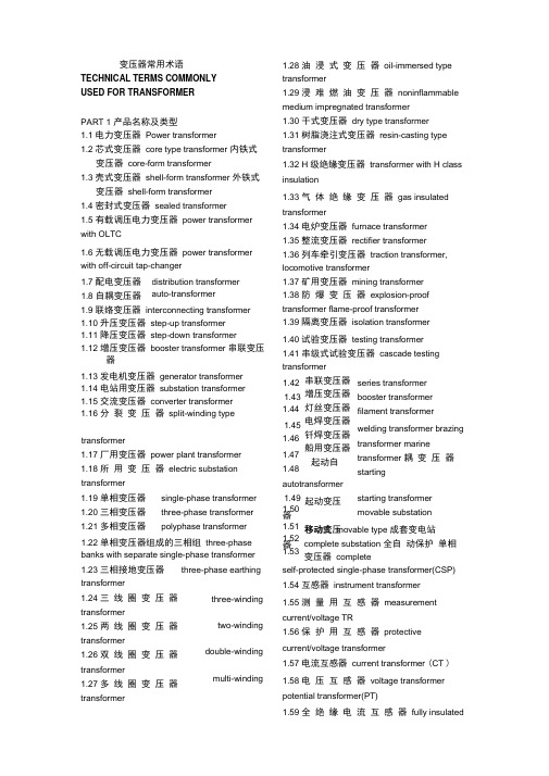
变压器常用术语TECHNICAL TERMS COMMONLYUSED FOR TRANSFORMERPART 1 产品名称及类型1.1 电力变压器Power transformer1.2 芯式变压器core type transformer 内铁式变压器core-form transformer1.3 壳式变压器shell-form transformer 外铁式变压器shell-form transformer1.4 密封式变压器sealed transformer1.5 有载调压电力变压器power transformer with OLTC1.6 无载调压电力变压器power transformer with off-circuit tap-changer 1.28 油浸式变压器oil-immersed type transformer1.29 浸难燃油变压器noninflammable medium impregnated transformer1.30 干式变压器dry type transformer1.31 树脂浇注式变压器resin-casting type transformer1.32 H 级绝缘变压器transformer with H class insulation1.33 气体绝缘变压器gas insulated transformer1.34 电炉变压器furnace transformer1.35 整流变压器rectifier transformer1.36 列车牵引变压器traction transformer, locomotive transformer1.7 配电变压器1.8 自耦变压器distribution transformer auto-transformer1.9 联络变压器interconnecting transformer 1.10 升压变压器step-up transformer1.11 降压变压器step-down transformer1.12 增压变压器booster transformer 串联变压器1.13 发电机变压器generator transformer1.14 电站用变压器substation transformer 1.15 交流变压器converter transformer1.16 分裂变压器split-winding type 1.37 矿用变压器mining transformer 1.38 防爆变压器explosion-proof transformer flame-proof transformer 1.39 隔离变压器isolation transformertransformer1.17 厂用变压器power plant transformer 1.18 所用变压器electric substation 1.40 试验变压器testing transformer 1.41 串级式试验变压器cascade testing transformer串联变压器增压变压器灯丝变压器电焊变压器钎焊变压器船用变压器起动自1.421.431.441.451.46transformer1.19 单相变压器1.20 三相变压器1.21 多相变压器single-phase transformerthree-phase transformerpolyphase transformer1.471.48autotransformer起动变压器移动变压器1.491.501.22 单相变压器组成的三相组three-phase banks with separate single-phase transformer 1.51 1.52 1.531.23 三相接地变压器transformerthree-phase earthing1.24 三线圈变压器transformer1.25 两线圈变压器transformer1.26 双线圈变压器transformer1.27 多线圈变压器transformerthree-windingtwo-windingdouble-windingmulti-windingseries transformerbooster transformerfilament transformerwelding transformer brazingtransformer marinetransformer 耦变压器startingstarting transformermovable substation移动式movable type 成套变电站complete substation 全自动保护单相变压器completeself-protected single-phase transformer(CSP)1.54 互感器instrument transformer1.55 测量用互感器measurementcurrent/voltage TR1.56 保护用互感器protectivecurrent/voltage transformer1.57 电流互感器current transformer (CT )1.58 电压互感器voltage transformerpotential transformer(PT)1.59 全绝缘电流互感器fully insulatedcurrent transformer1.60 母线式电流互感器bus-type current transformer1.61 绕线式电流互感器wound primary type current transformer1.62 瓷箱式电流互感器porcelain type current transformer1.63 套管用电流互感器bushing-type current transformer1.64 电容式电流互感器capacitor typecurrent transformer1.65 支持式电流互感器support-type current transformer1.66 倒立式电流互感器reverse type current transformer1.67 塑料浇注式电流互感器cast resin current transformer1.68 钳式电流互感器split-core type current transformer1.69 速饱和电流互感器rapid-saturable current transformer1.70 串级式电流互感器cascade-type current transformer1.71 剩余电流互感器residual current transformer1.72 电容式电压互感器capacitor type voltage transformer1.73 接地电压互感器earthed voltage transformer1.74 不接地电压互感器unearthed voltage transformer1.75 组合式互感器combined instrument transformer1.76 剩余电压互感器residual voltage transformer1.77 移圈调压器moving-coil voltage transformer1.78 动线圈moving winding1.79 自耦调压器autoformer regulator1.80 接触调压器variac1.81 感应调压器induction voltage regulator 1.82 磁饱和调压器magnetic saturationvoltage regulator1.83 电抗器reactor1.84 并联电抗器shunt reactor1.85 串联电抗器series reactor iron core reactor air core reactor concrete(cement) reactor 1.90 三相中性点接地电抗器three-phase neutral reactor1.92 单相中性点接地电抗器single-phase neutral earthing reactor1.93 起动电抗器starting reactor1.94 平衡电抗器smoothing /interphase reactor1.95 调幅电抗器modulation reactor1.96 消弧电抗器arc-suppression reactor1.97 消弧线圈arc-suppression coil1.98 阻波器,阻波线圈wave trap coil1.99 镇流器ballast1.100 密闭式sealed type1.101 包封式enclosed type1.102 户外式outdoor type1.103 户内式indoor type1.104 柱上式pole mounting type1.105 移动式movable type1.106 列车式trailer mounted type1.107 自冷natural cooling (ONAN)1.108 风冷forced-air cooling (ONAF)1.109 强油风冷forced-oil forced-air cooling(ONAF)1.110 强油水冷forced-oil forced-water cooling (ONWF)1.111 强油导向冷却forced-directed oil cooling (OFAN)1.112 强油导向风冷却forced-directed forced-air oil cooling(ODAF)1.113 恒磁通调压constant flux voltage variation(CFVV)1.114 变磁通调压variable flux voltage variation(VFVV)1.115 混合调压combined voltage variation(CbVV)PART2 基础词汇1.86 饱和电抗器1.87 铁心电抗器1.88 空心电抗器1.89 水泥电抗器saturable reactor2.1 千瓦kilowatt(kw) 2.2 兆瓦megawatt(MW) 2.3 京瓦gigawatt(GW) 2.4 千伏kilovolt(kV)symbol of product type of productrated voltage rated power rated current连 接 组 标 号connectionsymbol,impedance voltage rated frequency no-load losseddy-current loss hysteresis loss no-load current exciting current load loss 损 耗 additional losses,杂散损耗 stray losses 总损耗total losses 损耗比 loss ratio 冷却方式type of cooling 介质损耗 dielectric loss 介损角正切值 loss tangent 电压组合 voltage combination 电抗电压 reactance voltage 额定电压比 rated voltage ratio 电阻电压 resistance voltage 电压调整率 voltage regulation 相位差 phase displacement 相位差 zero-sequence impedance short-circuit impedance flux density current density 安匝数 number of ampere-turns轴向漏磁通 axial leakage flux 2.47 径向漏磁通 radial leakage flux2.48 循环电流 circulating current 2.49 热点 hot spot2.50 最热点 hottest spot 2.51 局部过热 local overheat 2.52 有功输出 active output 2.53 满容量分接 fully-power tapping 2.54 额定级电压 rated step voltage 2.55 最大额定电压 maximum rated voltage 2.56最 大 额 定 电 流 maximum ratedthrough-current2.57 绕 组 额 定 电 压 rated voltage of a winding2.58 额定短时电流 rated short time current 2.59 额定短时热电流 rated short thermal current2.60 额 定 连 续 热 电 流 rated continuous current2.61 额定动稳定电流 rated dynamic current 2.62 一次电流 /电压 primary current/voltage 2.63二 次 电 流 / 电 压 secondarycurrent/voltage2.64 实际电流比 actual transformation ratio of a current transformer2.65 实际电压比 actual transformation ratio of a voltage transformer2.66 二 次 极 限 感 应 电 动 势 secondary limiting e.m.f.2.67 互感器的二次回顾路 secondary circuit of CT and PT 2.68 定额 rating2.69 铁心噪声 noise of core 2.70 背境噪声 background noise 2.71 噪声水平 noise level 2.72 声级 sound level2.73 声功率级 sound power level 2.74 声级试验 sound level test2.75 声级测量 sound level measurement 2.76 水平加速度 horizontal acceleration 2.77 垂直加速度 vertical acceleration 2.78 地震 seism, earthquake 2.79 地震烈度 earthquake intensity 2.80 工频 power-frequency 2.81 中频 medium frequency 2.82 高频 high frequency2.5 2.6 千伏安 KVA 兆伏安 MVA 京伏安 GVA千乏 kilovar(kV Ar)兆乏megavar(MV Ar)京乏 gigavar(GV Ar)2.12 2.13 2.14 2.15 2.16 2.17 产品代号产品型号额定电压 额定容量 额定电流 2.18 symbol of connection 2.19 2.20 2.21 2.22 2.23 2.24 2.25 2.26 阻抗电压 额定频率空载损耗 涡流损耗 磁滞损耗 空载电流 激磁电流负载损耗 附加 2.27 supplementary load loss 2.28 2.292.30 2.31 2.32 2.33 2.34 2.35 2.36 2.372.38 2.39 2.41 2.42 2.432.44 2.452.46校 验 phase displacement 2.40 verification零序阻抗 短路阻抗 磁通密度 电流密度2.7 2.8 2.9 2.10 2.11 兆伏 megavolt(MV)京电子伏 giga-electron-volt(GEV)natural frequency of vibrationfrequency response harmonicsmeasurement 2.88 绝缘水平insulation level2.89 绝缘强度insulation strength, dielectric strength2.90 主绝缘main insulation2.91 纵绝缘longitudinal insulation2.92 内绝缘internal insulation2.93 外绝缘external insulation2.94 绝缘配合insulation co-ordination2.95 全绝缘uniform insulation2.96 半绝缘non-uniform insulation2.97 降纸绝缘reduced insulation2.98 中心点neutral point2.99 中心点端子neutral terminal2.100 正常绝缘normal insulation2.101 介电常数dielectric constant2.102 油纸绝缘系统oil-paper insulation system2.103 绝缘电阻insulation resistance2.104 绝缘电阻吸收比absorption ratio of insulation resistance2.105 绝缘击穿insulation breakdown2.106 碳化carbonization2.107 爬电距离creepage distance2.108 沿面放电creeping discharge2.109 放电discharge2.110 局部放电partial discharge2.111 局部放电测量measurement of partial discharge2.112 超声定位ultrasonic location, ultrasonic orientation2.113 破坏性放电disruptive discharge2.114 局部放电起始电压partial discharge inception voltage2.115 局部放电终止电压partial discharge extinction voltage2.116 过电压overvoltage short time overvoltage transient overvoltage switchingovervoltage atmosphericovervoltage2.121 额定耐受电压rated withstand voltage2.122 工频耐受电压power-frequency withstand voltage2.123 感应耐压试验induced overvoltage withstand test2.124 温升试验temperature-rise test2.125 温升temperature rise2.126 突发短路试验short-circuit test2.127 动热稳定thermo-dynamic stability2.128 冲击耐压试验impulse voltage withstand test2.129 雷电冲击耐受电压lightning impulsewithstand voltage2.130 操作冲击耐受电压switching impulsewithstand voltage2.131 雷电冲击lightning impulse2.132 全波雷电冲击full wave lightning impulse2.133 截波雷电冲击chopped wave lightning impulse2.134 操作冲击switching impulse2.135 操作冲击波switch surge, switch impulse2.136 伏秒特性voltage-time characteristics 2.137 截断时间time to chopping2.138 波前时间time to crest2.139 视在波前时间virtual front time2.140 半峰值时间time to half value crest2.141 峰值peak value, crest value2.142 有效值root-mean-square value2.143 标么值per unit value2.144 标称值nominal value2.145 电级electrode2.146 电位梯度potential gradient2.147 等电位,等位equipotential2.148 屏蔽shielding2.149 静电屏蔽electrostatic shielding2.150 磁屏蔽magnetic shielding2.151 静电屏electrostatic screen2.152 静电板electrostatic plate2.153 静电环electrostatic ring2.154 电磁感应electro-magnetic induction 2.155 电磁单元electro-magnetic unit2.83 振荡频率2.84 谐振频率2.85 自振频率2.86 频率响应2.87 谐波测量oscillating frequency resonance frequency2.117 短时过电压2.118 瞬时过电压2.119 操作过电压2.120 大气过电压2.156 有效面effective surface2.157 标准大气条件standard atmosphericcondition2.158 视在电荷apparent charge2.159 体积电阻volume resistance2.160 导电率admittance2.161 电导conductance, conductivity2.162 电晕放电corona discharge2.163 闪络flashover2.164 避雷器surge arrestor2.165 避雷器的残压residual voltage of an arrestor2.166 绝缘材料耐温等级temperature class of insulation2.167 互感器额定负荷rated burden of an instrument transformer2.168 准确级次accuracy class2.169 真值true value2.170 允差tolerance2.171 比值误差校验ratio error verification 2.172 电流误差current error2.173 电压误差voltage error2.174 互感器相角差phase displacement of instrument transformer2.175 复合误差composite error2.176 瞬时特性transient characteristic2.177 瞬时误差transient error2.178 额定仪表保安电流rated instrument security current2.179 二次极限感应电势secondary limitinge.m.f2.180 保安因子security factor2.181 额定准确限值的一次电流rated accuracy limit primary current2.182 误差补偿error compensation2.183 额定电压因子rated voltage factor2.184 准确限值因子accuracy limit factor2.185 开断电流switched current2.186 笛卡尔坐标,直角坐标Cartesian coordinate2.187 极坐标polar coordinate2.188 横坐标abscissa2.189 纵坐标ordinate 2.190 X- 轴X-axis2.191 复数complex number2.192 实数部分real component2.193 虚数部分imaginary component2.194 正数positive number2.195 负数negative number2.196 小数decimal2.197 四舍五入round off2.198 分数fraction2.199 分子numerator2.200 分母denominator2.201 假分数improper fraction2.202 钝角obtuse angle2.203 锐角acute angle2.204 补角supplementary angle2.205 余角complement angle2.206 平行parallel2.207 垂直perpendicular2.208 乘方involution2.209 开方evolution, extraction of root2.210 n 的 5 次方5th power of n2.211 幂exponent, exponential2.212 微分,差动differential, differentiate 2.213 积分,集成integral, integrate2.214 成正比proportio nal to2.215 成反比inversely proportional to2.216 概率probability2.217 归纳法inductive method2.218 外推法extrapolation method2.219 插入法interpolation method2.220 最大似然法maximum likelihood method2.221 图解法graphic method2.222 有限元法finite element method2.223 模拟法simulation method2.224 方波回应step response2.225 迭加电荷superimposed charge2.226 杂散电容stray capacitance2.227 无损探伤non-distractive flaw detection2.228 红外线扫描infrared scanning2.229 计算机辅助设计computer aided design(CAD)2.230 计算机辅助制造computer aided manufacturing(CAM)2.231 计算机辅助试验computer aidedtest(CAT)2.233 近似于approximate( approx)minute(rpm)2.235 速度velocity2.236 加速度acceleration2.237 重力加速度gravitational acceleration 2.238 引力traction2.240 件数pieces2.242 缩写abbreviation2.243 以下简称为hereinafter referred as xxx2.244 常用单位units commonly used2.245 包括缩写including abbreviations2.246 分米decimeter 厘米centimeter2.247 海里knot2.248 码yard2.249 磅pound(1b) 磅/平方英寸pound per square inch(ppsi)2.251 英制热量单位British thermal unit (BTU) 2.252 马力horsepower2.253 压强intensity of pressure2.254 帕斯卡Pascal(Pa)2.255 千帕kpa 兆帕Mpa2.256 粘度viscosity2.257 帕斯卡秒pascal.second2.258 泊poise 厘泊centipoises2.259 焦耳joule(J) 千瓦时kilowatt-hour(kwh)2.260 特斯拉tesla(T) 高斯gaue(Gs)2.261 奥斯特oersted(0e) 库仑coulomb(C) 2.262 微微库Pico-coulomb(PC)2.263 达因dyne2.264 摄氏度Celsius, centigrade( C)2.265 开尔文Kelvin 法拉farad(F)2.266 皮可法拉pico-farad(pF)2.268 立方分米cubic decimeter立方厘米cubic centimeter2.269 桶barrel 石油petroleum2.270 标准国际单位制standard international unit2.271 厘米-克秒单位制CGS unit 2.272 环境设备ambience apparatus2.273 校验calibration2.274 兼容性compatibility2.275 扩散系数diffusion coefficient2.276 故障fault2.277 公顷hectarePART3 典型产品结构3.1 芯式,内铁式core type3.2 壳式,外铁式shell type3.3 铁心core3.4 磁路magnetic circuit3.5 线圈winding, coil3.6 高压线圈HV winding3.7 中压线圈MV winding3.8 低压线圈LV winding3.9 调压线圈tapped winding, regulating winding3.10 高压引线high-voltage leads3.11 中压引线mid-voltage leads3.12 低压引线low-voltage leads3.13 夹件clamping frame3.14 上部夹件upper clamping3.15 下部夹件lower clamping3.16 线圈压紧螺栓winding compressing bolt 3.17 线圈压紧装置winding compressing device3.18 线圈端部绝缘end insulation of winding3.19 器身定位装置positioning device for active-part3.20 定位装置fixing device3.21 铁心垫脚foot-plate of core3.22 垫脚foot-pad3.23 分接引线tapping leads, tap leads3.24 引线支架supporting frame for leads3.25 无励磁分接开关non-excitation tap-changer3.26 无载分接开关off-circuit tap-changer3.27 分接选择器tap selector3.28 有载分接开关on-loadtap-changer(OLTC) on-circuit tap-changer3.29 切换开关diverter switch3.30 选择开关selector switch3.31 转换选择器change-over selector2.234 每分钟转数revolution per3.32 粗选择器coarse tap selector3.33 触头组set of contacts3.34 过度触头transition contacts3.35 过度阻抗transition impedance3.36 有载开关操纵机构operating mechanism of OLTC3.37 驱动机构driving mechanism3.38 电动机构motor drive3.39 垂直转动轴vertical driving shaft 水平转动轴horizontal driving shaft3.40 伞尺轮盒bevel gear box3.41 防雨罩drip-proof cap3.42 联轴节coupling3.43 最大分接maximum tapping 最小分接minimum tapping3.44 额定分接rated tapping, principal tapping3.45 固定分接位置数number of inherent tapping positions 工作分接位置数number of service tapping positions3.46 主分接principal tap, main tap 正分接plus tapping 负分接minus tapping3.47 分接变换操作tap-changer operation tap position indicator tapping voltage of atapping current of atapping power of awinding3.52 分接范围tapping range3.53 分接量tapping quantities3.54 分接因子tapping factor3.55 分接工作能力tapping duty3.56 分接线tapping step3.57 分接线tapping connection3.58 分接引线tapping lead3.59 小车支架及滚轮bogie frame and wheel3.61 箱底tank bottom3.62 箱盖tank cover3.63 箱沿tank rim3.64 垫脚垫块supporting block for foot-pad 3.65 联管接头tube connector3.66 联接法兰connecting flange3.67 加强筋,加强板stiffener3.68 油箱垂直加强铁vertical stiffening channel of tank wall3.69 油箱活门oil sampling valve3.70 放油活门oil drainningvalve3.71 冷却器cooler3.72 集中安装concentrated installation 3.73 集中安装强油循环风冷器concentrated installation of forced-oil circulating air cooler3.74 冷却器进口inlet of cooler冷却器出口outlet of cooler3.75 潜油泵oil-submerged pump3.76 油流继电器oil flow relay3.77 净油器oil filter3.78 虹吸净油器oil siphon filter3.79 散热器radiator3.80 片式散热器panel type radiator3.81 管式散热器tubular radiator3.82 放油塞oil draining plug3.83 放气塞air exhausting plug3.84 蝶阀radiator valve butterfly valve3.85 风扇支架supporting frame for fan motors3.86 风扇及电机fan and motor3.87 风扇接线盒connecting box for fan motors3.88 储油柜conservator3.89 油位计oil-level indicator3.90 气体继电器gas relay, buchholz realy 3.91 皮托继电器pitot relay3.92 储油柜联管elbow joint for conservator 3.93 有载开关用储油柜conservator for OLTC3.94 有载开关用气体继电器gas relay for OLTC3.95 联管tube connector3.96 吸湿器dehydrating breather3.97 铭牌rating plate3.98 温度计thermometer3.98 指示仪表柜cabinet panel for indicating instruments3.99 风扇控制柜cabinet panel for fan motor control3.100 压力释放阀pressure-relief valve3.101 安全气道explosion-proof pope3.102 膨胀器expander3.103 主排气导管main gas-conduit3.104 分支导气管branching gas-conduit3.105 滤油界面tube connector for oil-filter 3.106 温度计座thermometer socket3.107 储油柜支架supporting frame for conservator3.108 高压套管HV bushing3.48 分接位置指示器3.49 线圈分接电压winding3.50 线圈分接电流winding3.51 线圈分接容量3.109 高压套管均压球equipotential shielding for HV bushing3.110 高压零相套管HV neutral bushing, HV bushing phase03.111 中压套管MV bushing3.112 中压零相套管MV neutral bushing,MV bushing phase03.113 低压套管LV bushing3.114 接地套管earthing bushing3.115 极性polarity3.116 极化polarization3.117 高压套管储油柜conservator for HV bushing3.118 相间隔板interphase insulating barrier 3.119 吊攀lifting lug3.120 安装轨道installation rail3.121 相序标志牌designation mark of phase sequence3.122 接地螺栓earthing bolt3.123 视察窗inspection hole3.124 手孔handhole3.125 人孔manhole3.126 MR 有载开关MR OLTC3.127 ABB 有载开关ABB OLTC3.128 伊林有载开关ELIN OLTC3.129 F& 套管F&G bushingPART4 铁心结构4.1 多框式铁心multi-frame type core4.2 三相三柱铁心three-phase three-limb core4.3 三相五柱铁心three-phase five-limb core4.4 卷铁心wound core4.5 冷轧晶粒取向硅钢片cold-rolled grain-oriented silicon sheet steel4.6 晶粒crystalline grain4.7 高导磁硅钢片HI-B silicon sheet steel 4.8 铁心片core lamination4.9 一迭铁心 a lamination stock4.10 铁心迭积图lamination drawing, lamination diagram4.11 迭片lamination4.12 迭片系数lamination factor4.13 空间利用系数space factor4.14 层间绝缘layer insulation 4.15 斜接缝mitring4.16 45°斜接缝45° mitred joint4.17 斜接缝的交错排列方式over-lay arrangement for mitred joints of lamination 4.18 重迭overlap4.19 铁心油通oil-duct of core4.20 铁心气道air ventilating duct of core4.21 阶梯接缝stepped lay joint4.22 对接铁心butt jointed core4.23 渐开线铁心evolute core, involute core 4.24 空气隙air gap4.25 铁心拉板tensile plate of core limb, core drawplate4.26 铁心柱core limb, core lge4.27 轭,铁轭yoke4.28 上轭upper yoke下轭lower yoke旁轭side yoke, return yoke4.29 环氧绑扎带epoxy-bonded bandage4.30 轭拉带yoke tensile belt4.31 铁轭拉带banded band of core yoke4.32 上轭顶梁top jointing beam of upper yoke 4.33 侧梁side beam4.34 夹件clamping frame4.35 铁心夹件core clamps, coreframe4.36 铁轭夹件yoke clamping, yoke clamps 4.37 上夹件upper yoke clamping, upper yoke clamps4.38 下夹件lower yoke clampings, lower yoke clamps4.39 夹件腹板web of yoke clamping4.40 夹件肢板limb of yoke clamping4.41 夹件加强stiffening plate of clamping4.42 压线圈的压钉winding compressing bolt4.43 压钉螺母nut for compressing bolt4.44 弹簧压钉compressing bolt with spring 4.45 油缸压钉compressing bolt with hydraulic damper4.46 线圈支撑架winding supporter4.47 线圈支撑架 winding supporting plate 4.48 垫脚 foot pad 4.49 定位孔 positioning hole4.50 带螺母的定位柱 positioning stud 4.51 拉螺杆 tensile rod5.15 部 分 纠 结 式 线 圈 partial-interleaved winding5.16 插花纠结式线圈 sandwich-interleaved winding5.17 内 屏 连 续 式 线 圈 4.52 夹件夹紧螺杆 yoke clamping bolt 4.53 铁心接地片 core earthing strip 4.54 铁心地屏 4.55 旁轭地屏 4.56 接地屏蔽 earthing screen of code earthing screen of side yoke earthing shield 4.57 铁心窗高 core window height 4.58 中心距 M center line distance M 4.59 铁心中间距 center distance between lombs 4.60 木垫块 4.61 迭片系数 4.62 铁心的级4.63 心 柱 外 接 圆 core leg 4.64 铁心端面 lamination 4.65 木棒 wood padding block laminationfactor stage of lamination stacks circumscribed circle of innershield-continuous winding5.18 插 入 电 容 式 线 圈 capacitor shield winding5.19 高 串 联 电 容 线 圈 high series capacitance winding5.20 双饼式线圈 twin-disk winding 5.21 交 错 式 线 圈 sandwich winding, staggered winding5.22 螺 旋 式 线 圈 helical winding, helix winding5.23 半螺旋式线圈 semi-helical winding4.66 定位板 PART5 线圈结构5.1 圆筒式线圈 5.2 层式线圈 5.3饼式线圈 core surface perpendicular to wood bar, wood rod positioning plate cylindrical winding5.24 单列 螺 旋式 线圈 single-row helicalwinding5.25 双列 螺旋式 线圈 double-row helicalwinding5.26 三列 螺旋式 线圈 three-row helical5.4 单层圆筒式线圈 winding 5.5 双层圆筒式线圈winding 5.6 多层圆筒式线圈 winding 5.7 大型层式 线圈 winding 5.8 分段圆筒式线圈 5.9 分段多层圆筒线圈layer winding disk winding single layer cylindricaldouble layer cylindrical multi-layer cylindrical large size long layer sectional layer winding sectional multi-layer winding5.27 短螺旋式线圈 short helical winding 5.28 螺旋式线 圈引 出端的 固定 terminal fixing for helical winding 5.29 分裂式线圈 split winding 5.30 分段式线圈 sectional winding 5.31 箔式线圈 foil winding5.32 全 绝 缘 线 圈 uniformly insulated winding5.33 分 级 绝 缘 线 圈 gradedly insulated winding, winding with non-uniform insulation 5.34 第三线圈 tertiary winding 5.35 高压线圈 high-voltage winding 5.36 中 压 线 圈 mid-voltage winding, intermediate voltage windingwinding5.10 连续式线圈 continuous winding 5.11 半 连 续 式 线 圈 semi-continuous 5.37 低压线圈 5.38 调压线圈 windinglow-voltage winding regulating winding,tappedwinding 5.12 纠结式线圈 interleaved winding 5.13 纠结饼式线圈 interleaved disc winding5.14 纠 结 — 连 续 式 线 圈 interleaved-continuous winding5.39 辅助线圈 5.40 平衡线圈 5.41 稳定线圈 5.42 公共线圈 5.43 串联线圈 5.44 连耦线圈 auxiliary winding balance winding stabilizing winding common winding series winding coupling winding5.45 励磁线圈 exciting winding, energizing winding5.46 一次线圈 primary winding 5.47 二次线圈 secondary winding 5.48 左绕 left-wound 5.49 右绕 right-wound 5.50 星形联结 star connection 5.51 三角形联结 delta connection 5.52 曲折形联结 zigzag connection 5.53 T 形联结 scott connection5.54 开口三角形联结 open-delta connection 5.55 开口线圈 open winding5.57 线段 winding disk, winding section 5.58 线层 winding layer 5.59 匝绝缘 turn insulation 5.60 层绝缘 layer insulation5.61 段 绝 缘 insulation between disks, section insulation5.62 端绝缘 end insulation 5.63 顶部端环 top support ring 5.64 分接头 tapping terminal 5.65 分接区 tapping zone5.66 段间横垫块 radial spacer between disks 5.67 燕尾垫块 chock 5.68 燕尾撑条 dovetail strip 5.69 垫块的厚度 spacer thickness 5.70 垫块的宽度 spacer width 5.71 撑条 stick, duct strip 5.72 轴向撑条 axial strip 5.73 油道 oil-duct, oil passage 5.74 径向油道 radial oil-duct 5.75 段间油道 oil-duct between disks 5.76 段 间 过 度 联 线 transfer connection between disks5.77 段间换位联线 transposed connection between disksS 弯 S-bend 线圈起始端 initial terminal of winding 线圈终端 轴向深度 径向深度 绝缘纸筒 匝间绝缘 绝缘角环5.86 线匝间垫条 insulating filling strips betweenturns 5.87 分数匝fractional turn 5.88 整数匝integer turn5.89 近似一圈 approximate roll5.90 并绕导线 parallel wound conductors 5.91 多股导线 multi-strand conductors 5.92 电磁线 electro-magnetic conductor 5.93 组合导线 composite conductor 5.94 换 位 导 线 transposed conductor, transposed cable5.95 纸包线 paper wrapped conductor 5.96 纸包导线 covered conductor 5.97 漆包线 enameled conductor 5.98 圆线 round wire5.99 硬 拉 铜 导 线 hard drawn copper conductor5.100 退火导线 annealed conductor 5.101 玻 璃 丝 包 线 glass-fiber covered conductor5.102 纸槽 paper channel 5.103 绑线 binding wire 5.104 绑绳 binding rope 5.105 静电板 electrostatic plate 5.106 静电环 electrostatic ring5.107 端部电容环 capacitive layer end ring 5.108 端 部 电 容 屏 capacitive layer end screen5.109 屏蔽环 shielding ring 5.110 屏蔽线 shielding conductor 5.111 屏蔽角环 shroud petal 5.112 绝缘包扎 insulation wrapping 5.113 线圈总高度 overall height of winding 5.114 铜线高度 copper height of winding 5.115 线圈调整 trimming of winding 5.116 线 圈 浸 漆 varnish impregnation of winding5.117 线圈的换位 transposition of winding 5.118 标准换位 standard transposition 5.119 分组换位 transposition by groups 5.120 线 圈 展 开 图 planiform drawing of winding5.121 线 圈 的 干 燥 与 压 缩 drying and compressing of winding5.122 绝 缘 的 压 缩 收 缩 率 shrinkage of5.78 5.79 5.80 final terminal of winding axial depth radial depth insulating cylinder turn insulation5.815.825.83 5.84insulating angled ring (collar5.85ring)insulation under compression5.123 无氧铜导线deoxygenized copper conductor5.124 铝合金导线aluminum-alloy conductorPART6 油箱结构及附件6.1 钟罩式油箱bell type tank6.2 上节油箱upper part of tank6.3 下节油箱bottom part of tank6.4 箱壁tank wall6.5 带磁屏箱壁tank wall with magnetic shield 6.6 箱底tank bottom6.7 箱盖tank cover6.8 箱沿tank rim6.9 箱沿护框pad frame for tank rim gasket 6.10 边缘垫片rim6.11 加强筋, 加强板stiffener6.12 联管头tube connecting flange6.13 放油活门draining valve6.14 油样活门oil sampling valve6.15 油样活塞oil sampling plug6.16 闸阀gate valve6.17 蝶阀butterfly valve6.18 球阀ball valve6.19 压力释放阀pressure relief valve6.20 安全气道explosion-proof pipe6.21 真空接头connecting flange for evacuation6.22 滤油接头connecting flange for oil filter 6.23 水银温度计pocket for mercury thermometer6.24 铭牌底板base plate of rating plate6.25 手孔handhole6.26 人孔manhole6.27 升高座ascending flanged base turret6.28 吊攀lifting lug6.29 千斤顶支座jacking lug6.30 定位钉positioning pin6.31 盖板cover plate 6.32 临时盖板temporary cover plate6.33 带隔膜储油柜conservator with rubber diaphragm6.34 带胶囊储油柜conservator with rubber bladder6.35 沉淀盒precipitation well6.36 导气管air exhausting pipe6.37 导油管oil conduit6.38 吊环lifting eyebolt6.39 有围栏的梯子ladder with balustrade6.40 适形油箱form-fit tank6.41 呼吸器breather6.42 气体继电器gas relay, buchholz relay6.43 皮托继电器pitot relay6.44 流动继电器flow relay6.45 风冷却器air cooler6.46 水冷却器water cooler6.47 冷却器托架bracket for cooler6.48 冷却器拉杆tensile rod for cooler6.49 潜油泵oil-submerged pump6.50 流量flow quantity6.51 扬程lift6.52 控制箱control box6.53 控制盘control panel6.54 端子箱terminal box6.55 端子排terminal block6.56 风扇接线盒connecting box for fan-motors6.57 金属软管metallic hose6.58 封闭母线联结法兰joint flange for enclosed bus-bar6.59 管式油位指示器tubular oil-level indicator6.60 磁铁式油位指示器magnetic type oil-level indicatorPART7 铁心制造7.1 产品制造manufacturing of products7.2 硅钢片纵剪silicon steel sheet slitting7.3 硅钢片横剪silicon steel sheet cutting tolength7.4 多刀滚剪机multi-disk-cutter slitting machine7.5 纵剪slitting横剪cut-to-length7.6 纵剪生产线slitting line7.7 横剪生产线cut-to-length line7.8 开卷机decoiler7.9 毛刺burr7.10 铁心片预迭pre-stacking of core lamination7.11 铁心迭装core assembly7.12 铁心迭片core lamination7.13 选片pre-selection of lamination7.14 迭片lamination stacking7.15 两片一迭stacked by two-sheet7.16 打(敲)齐knock to even7.17 迭装流转台core assembly tilting platform7.18 不迭上轭core stacking without upper yoke7.19 打铁心用垫块knock block7.20 铁心料盘lamination stocking tray7.21 卷铁心机core winding machine7.22 铁心退火core annealing7.23 铁心中间试验interprocess core test7.24 片的角度偏差angular misalignment of lamination7.25 宽度偏差width deviation7.26 长度偏差length deviation7.27 铁心的垂直度verticality of core7.28 铁心起立tilt the core into vertical position7.29 迭片的定位挡板positioning stopper for core assembly7.30 硅钢片的涂漆varnish coating of silicon steel sheet7.31 片间绝缘试验lamination insulation test7.32 半导体粘带semi-conductive adhesive tape7.33 半干环氧粘带semi-cured epoxy adhesive tape7.34 粘带的固化cure of adhesive tape7.35 夹紧铁心工具clamping tools for core 7.36 铁心柱的夹紧装置tightening device for core leg7.37 铁心翻转台tilting platform of core7.38 螺旋千斤顶screw jack7.39 水平尺level gauge, level instrument7.40 专用套筒搬手special socket spanner 7.41 迭片的工艺孔punching hole on the lamination for manufacturing purpose7.42 迭板导棒guiding bar for core assembly 7.43 力短搬手torque spanner, torque wrench7.44 角度测量平台angular measuring platform7.45 切口防锈漆antirust coating for cutting edges7.46 铁心的油道撑条strips for core oil-ducts7.47 撑条粘结sticking of strips7.48 级间衬纸insulating paper between core stages7.48 冲孔模hole punching die7.49 缺口模notch punching die7.50 皮裙leather apron7.51 防护袖protective sleeve7.52 护臂shoulder guard7.53 护腿shin guardPART8 线圈制造8.1 绕线机,卷线机winding machine8.2 卧式绕线机horizontal winding machine 8.3 立式绕线机vertical winding machine8.4 绕盘架bracket for conductor drums, bracket for wire drums8.5 导线盘conductor drum, wire drum8.6 导线拉紧装置conductor tensile device, wire tensile device。
变压器专业英语翻译
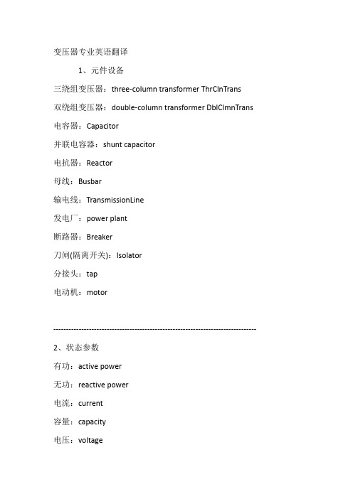
变压器专业英语翻译1、元件设备三绕组变压器:three-column transformer ThrClnTrans双绕组变压器:double-column transformer DblClmnTrans 电容器:Capacitor并联电容器:shunt capacitor电抗器:Reactor母线:Busbar输电线:TransmissionLine发电厂:power plant断路器:Breaker刀闸(隔离开关):Isolator分接头:tap电动机:motor-------------------------------------------------------------------------------- 2、状态参数有功:active power无功:reactive power电流:current容量:capacity电压:voltage档位:tap position无功损耗:reactive loss有功损耗:active loss功率因数:power-factor功率:power功角:power-angle电压等级:voltage grade空载损耗:no-load loss铁损:iron loss铜损:copper loss空载电流:no-load current阻抗:impedance正序阻抗:positive sequence impedance 负序阻抗:negative sequence impedance 零序阻抗:zero sequence impedance电阻:resistor电抗:reactance电导:conductance电纳:susceptance无功负载:reactive load 或者QLoad有功负载: active load Load遥测:YC(telemetering)遥信:YX励磁电流(转子电流):magnetizing current 定子:stator功角:power-angle上限:upper limit下限:lower limit并列的:apposable高压: high voltage低压:low voltage中压:middle voltage电力系统power system发电机generator励磁excitation励磁器excitor电压voltage电流current母线bus变压器transformer升压变压器step-up transformer高压侧high side输电系统power transmission system输电线transmission line固定串联电容补偿fixed series capacitor compensation 稳定stability电压稳定voltage stability功角稳定angle stability暂态稳定transient stability电厂power plant能量输送power transfer交流AC装机容量installed capacity电网power system落点drop point开关站switch station双回同杆并架double-circuit lines on the same tower 变电站transformer substation补偿度degree of compensation高抗high voltage shunt reactor无功补偿reactive power compensation故障fault调节regulation裕度magin三相故障three phase fault故障切除时间fault clearing time极限切除时间critical clearing time切机generator triping高顶值high limited value强行励磁reinforced excitation线路补偿器LDC(line drop compensation)机端generator terminal静态static (state)动态dynamic (state)单机无穷大系统one machine - infinity bus system 机端电压控制AVR电抗reactance电阻resistance功角power angle有功(功率)active power无功(功率)reactive power功率因数power factor无功电流reactive current下降特性droop characteristics斜率slope额定rating变比ratio参考值reference value电压互感器T分接头tap下降率droop rate仿真分析simulation analysis传递函数transfer function框图block diagram受端receive-side裕度margin同步synchronization失去同步loss of synchronization 阻尼damping摇摆swing保护断路器circuit breaker电阻:resistance电抗:reactance阻抗:impedance电导:conductance电纳:susceptance导纳:admittance电感:inductance电容: capacitance-------------------------------------------------------------------------------- Absorber Circuit ——吸收电路AC/AC Frequency Converter ——交交变频电路AC power control ——交流电力控制AC ower Controller ——交流调功电路AC Power Electronic Switch ——交流电力电子开关Ac Voltage Controller ——交流调压电路Asynchronous Modulation ——异步调制Baker Clamping Circuit ——贝克箝位电路Bi-directional Triode Thyristor ——双向晶闸管Bipolar Junction Transistor-- BJT ——双极结型晶体管Boost-Buck Chopper ——升降压斩波电路Boost Chopper ——升压斩波电路Boost Converter ——升压变换器Bridge Reversible Chopper ——桥式可逆斩波电路Buck Chopper ——降压斩波电路Buck Converter ——降压变换器Commutation ——换流Conduction Angle ——导通角Constant Voltage Constant Frequency --CVCF ——恒压恒频Continuous Conduction--CCM ——(电流)连续模式Control Circuit ——控制电路Cuk Circuit ——CUK斩波电路Current Reversible Chopper ——电流可逆斩波电路Current Source Type Inverter--CSTI ——电流(源)型逆变电路Cycloconvertor ——周波变流器DC-AC-DC Converter ——直交直电路DC Chopping ——直流斩波DC Chopping Circuit ——直流斩波电路DC-DC Converter ——直流-直流变换器Device Commutation ——器件换流Direct Current Control ——直接电流控制Discontinuous Conduction mode ——(电流)断续模式displacement factor ——位移因数distortion power ——畸变功率double end converter ——双端电路driving circuit ——驱动电路electrical isolation ——电气隔离fast acting fuse ——快速熔断器fast recovery diode ——快恢复二极管fast recovery epitaxial diodes ——快恢复外延二极管fast switching thyristor ——快速晶闸管field controlled thyristor ——场控晶闸管flyback converter ——反激电流forced commutation ——强迫换流forward converter ——正激电路frequency converter ——变频器full bridge converter ——全桥电路full bridge rectifier ——全桥整流电路full wave rectifier ——全波整流电路fundamental factor ——基波因数gate turn-off thyristor——GTO ——可关断晶闸管general purpose diode ——普通二极管giant transistor——GTR ——电力晶体管half bridge converter ——半桥电路hard switching ——硬开关high voltage IC ——高压集成电路hysteresis comparison ——带环比较方式indirect current control ——间接电流控制indirect DC-DC converter ——间接DC- DC转换器insulated-gate bipolar transistor---IGBT ——绝缘栅双极晶体管intelligent power module---IPM ——智能功率模块integrated gate-commutated thyristor---IGCT ——集成门极换流晶闸管inversion ——逆变latching effect ——擎住效应leakage inductance ——漏感light triggered thyristo---LTT ——光控晶闸管line commutation ——电网换流load commutation ——负载换流loop current ——环流。
变压器英译词汇表

Chopped wave lightning impulse
49 冲击伏秒特性
Voltage time characteristics of impulse
50 爬电距离
Creepage distance
51 体积电阻
Volume resistance
52 截断时间
Time to chopping
Discharge
30 局部放电
Partial discharge
31 破坏性放电
Disruptive discharge
32 局部放电起始电压
Partial discharge inception voltage
33 局部放电终止电压
Partial discharge extinction voltage
58 标称值
Nominal value
59 导电率
Admittance
60 电导
Conductance, conductivity
61 介质损耗率
Dielectric loss
62 介损角的正切值
Loss tangent
63 电晕放电
Corona discharge
64 闪络
Flashover
65 内(外)绝缘
154 焦耳
Joule
155 千瓦时
Kilowatt-hour
156 特斯拉
78 复合误差
Composite error
79 暂态特性(误差) Transient characteristics(error)
80 额定短时热电流
Rated short thermal current
81 额定连续热电流
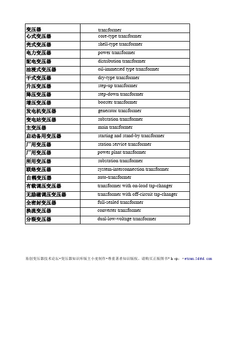
变压器汉英英汉技术词汇(第一章 变压器种类)
through type current transformer
瓷箱式电流互感器
porcelain type current transformer
套管电流互感器
bushing-type current transformer
电容式电流互感器
capacitor type current transformer
电弧炉变压器
arc furnace transformer
工频感应炉变压器
power frequency induction furnace transformer
电阻炉变压器
resistance furnace transformer
矿热炉变压器
ore furnace transformer
盐浴炉变压器
system-interconnection transformer
自耦变压器
auto-transformer
有载调压变压器
transformer with on-load tap-changer
无励磁调压变压器
transformer with off-circuit tap-changer
全密封变压器
起动变压器
starting transformer
移动变压器
movable substation
无危害变压器
fail-safe transformer
抗短路变压器
short-circuit proof transformer
中频变压器
intermediate-frequency transformer
保护用电流/电压互感器
protective current/voltage transformer
变压器(电气工程专业)外文翻译
英文资料及其翻译TransformerTypes and Construction of TransformerA transformer is a device that alternating current electric energy at one voltage level into alternating current electric energy at another voltage level through the action of a magnetic field.It consists of two or more coils wire wrapped around a common ferromagnetic core.These coils are (usually)not directly connected. The only connection between the coils is the common magnectic flux presen within the core.One of the transformer windings is connected to a source of ac electric power,and the second(and perhaps third) transformer winding supplies electric power to loads. the transformer winding connected to the power souce is called the primary winding or input winding.and the winding connected to the loads is called the secondary winding or input winding.If there is a third winding on the transformer,it is called the tertiary winding.Power transformer are constructed on one of two types of cores.one type of construction consists of a simple rectangular laminated piece of steel with the transformer windings wrapped around two sides of the rectangle.This type of construction is know as coreform .The other type consists of three-legged laminated core with the windings wrapped around the center leg .This type of construction is know as shell form.In either case,the core is constructed of thin laminations electrically isolated form each other in order in order to reduce eddy currents to a minimum.The primary and secondary windings in a physical transformer arewrapped one on top of the other with the low-voltage winding innermost.Such an arrangement severs two purposes: 1.It simplifies the problem of insulating the high- voltage winding from the core.2.It results in much less leakage flux than would be the two windings were separated by a distance on the core.Power transformer are given a variety of different names, depending on their use in power systems.A transformer connected to the output of a generator and used to step its voltage up to transformer levels is sometimes called unit transformer. The transformer ai the other end of the transformer line,which steps the voltage down from transmission levels to distribution levels,is called a substation transformer.Finally,the transformer that takes the distribution voltage and steps is down to the final voltage ai which the power is actually used is called a distribution transformer.All these devices are essentially the same-the only difference among them is their intended use.In addition to the various power transformer, two special-purpose transformers are used with electric machinery and power systems.The first of these special transformers is a device specially designed to sample a high voltage and produce a low secondary voltage directly proportional to it.Such a transformer is called a potential transformer.A power transformer also produces a secondary voltage directly proportional to its primary voltage;the difference between a potential transformer and a power transformer is that the potential transformer is designed to handle only a very small current.The second type of special transformer is a device designed to provide a secondary current.much smaller than but directly proportional to its primary current.This device is called a currenttransformer.Cirtcuit BreakersA circuit breaker is mechanical switching device capable of making,and breaking currents under normal circuit conditions and also making.carring for a specified time ,and mediujm in which circuit interruption is performed may be designated by a suitable prefix, for example,air-blastcircuit breaker,oil circuit breaker.The circuit breakers currently in use can be dlassified into the following categories according to the arc-quenching principles:air swetches oel ciryit breakers,minmum-oil circuit breakers,air-blast circuit breakers,the magenetic air circuit breakers,minimum-oilcircuit breakers,aer-blast circuit breakers,the by voltage,insulation levelcurrent,interrupting capabilities,transient recovery coltage,interrupting tiome,and trip delay.The nameplate on a circuit breaker usually indicates:1.The maximum steady-state current it can carry, 2. The maximum interrupting current,3. The maximum line voltage,4.The interrupting time in cycles, The interrupting time in may last form 3 to 8 cycles on a 60 Hz system. To interrubt large currents quickly, we have to ensure rapid cooling. High-speed interruption lunits the damage transmission lines and equipment and, equally important,it helps to mainmain the stability of the system whenever a contingency occurs. The main parts of a circuit breaker are usually:arc-quenching chamber (or interrupter with moving and fixed contacts) operating mechanism and supporting structures.Air Switches-With increasing currents and voltages, spring-actiondriving mechanisms were developed to reduce contact buring by faster-opening ter,main contacts were fitted with arcing contacts of special material and shape,which opend after and closed before the main contacts.Further improvements of the air switch were the bursh-type contact with a wiping and cleaning function,the insulating barrier leading to arc chutes,and blowout coils with excellent arc-extinguishing properties.These features,as well as the horn gap contact,are still in use in low voltage as and de breakers.Oil Circuit Breaker Around 1900, in order to cope with the new requirement for “interrupting capacity”,AC switches were immersed in a tank of oil. Is very effective in quenching the arc and establishing the open break after current zero.Deion grids,oil-blast features,pressure-tight joints and vents,new operating mechanisims,and multiple interrupter were introucedover several decades to make the oil circuit breaker reliable apparatus for system voltage up to 362kV变压器变压器的类型和结构变压器是一个通过磁场作用将一个交流电压值变成另一个电压值的设备。
变压器常用中英对照

1、安全隔离变压器safety isolating transformer2、安全特低电压(SELV)safety extra-low voltageB1、棒式电流互感器bar primary type current transformer2、包封线圈的干式变压器encapsulated-winding dry-type transformer3、包封线圈干式电抗器encapsulated-winding dry-type reactor4、饱和电抗器saturable reactor5、保护用电流互感器protective current transformer6、保护用电压互感器protective voltage transformer7、保护装置(电容式电压互感器)protective device (of a capacitor voltage transformer)8、变磁通调压variable flux voltage variation (VFVV)9、变流变压器converter transformer10、变压器transformer11、变压器效率efficiency of transformer12、并联电抗器shunt reactor13、并联控制装置parallel control devices14、饼式线圈disc winding15、箔式线圈foil winding16、波纹式油箱corrugated type tank17、不接地电压互感器unearthed voltage transformerC1、操作计数器operation counter2、操作循环cycle of operation3、测量用电流互感器measuring current transformer4、测量用电压互感器measuring voltage transformer5、层式线圈layer winding6、叉花纠结式线圈sandwich-interleaved winding7、厂用变压器(发电厂用变压器) station service transformer8、插入电容式线圈capacitor shield winding9、充满油的密封系统sealed, completed filled system10、串级(电磁)式电流互感器cascade (inductive) current transformer11、串级(电磁)式电压互感器cascade (inductive) voltage transformer12、串级试验变压器cascade transformer13、串联电抗器series reactor14、串联绕组series winding15、船用变压器marine transformer16、触头组set of contacts17、储油柜oil conservator18、储油柜系统conservator system19、磁分路magnetic shunt20、磁箱式电流互感器porcelain-case type current transformer21、磁性调压器magnetic control voltage regulator22、粗调选择器coarse change-over selector1、带气垫的密封式油箱系统sealed-tank system with gas cushion2、带散热管的油箱tank with bend pipe3、单铁心式电流互感器single-core type current transformer4、单相单柱旁轭式铁心single-phase three-limb core5、单相二柱式铁心single-phase two-limb core6、倒立式电流互感器inverter-type current transformer7、电磁单元(电容式电压互感器) electromagnetic unit (of a capacitor voltage transformer)8、电动机构motor-drive mechanism9、电动机构的手动操作manual operation of motor-device mechanism10、电化学用整流变压器electro-chemistry rectifier transformer11、点火变压器ignition transformer12、电弧炉变压器arc furnace transformer13、电抗电压reactance voltage14、电抗器reactor15、电缆式电流互感器cable type current transformer16、电力变压器power transformer17、电铃变压器bell transformer18、电流互感器current transformer19、电流扩大值(测量用电流互感器的)extended rating current(of a measuring current transformer )20、电流误差current error21、电炉变压器furnace transformer22、电容分压器(电容式电压互感器)capacitor voltage divider (of a capacitor voltage transformer)23、电容分压器的分压比voltage ratio of a capacitor divider24、电容式电压互感器capacitor voltage transformer25、电压互感器voltage transformer26、电压降或电压升(指定负载下的)voltage drop or rise for a specified load condition27、电压调整率(指定复式下的)voltage regulation for a specified load condition28、电压误差voltage error29、电阻电压resistance voltage30、电阻炉变压器resistance furnace transformer31、电阻式温度计resistance-type thermometer32、叠积式铁心laminated core33、低压端子(电容式电压互感器的)low voltage terminal (of a capacitor voltage transformer)34、低压绕组low-voltage winding35、端(部电容)环end ring36、短路匝short-circuited turn37、短路阻抗(一对绕组的)short-circuit impedance (of a pair of winding)38、端(部电容)屏end screen39、对应端子corresponding terminals40、独立绕组变压器separate winding transformer41、多框式铁心multi frame type core42、多绕组变压器multi-winding transformer43、多铁心式电流互感器multi-core type current transformer44、惰性气体压力系统inert gas pressure systemE1、额定参数rated quantities2、额定电流(变压器或并联电抗器绕组上的)rated current(of a winding of a transformer or shunt reactor)3、额定电流比(电流互感器的)rated transformer ratio (of a current transformer)4、额定电压比(电流互感器的)rated transformer ratio (of a voltage transformer)5、额定电压比(绕组的)rated voltage ratio (of a winding)6、额定电压比(电压互感器的)rated transformation ratio (of a voltage transformer)7、额定电压系数rated voltage factor8、额定动稳定电流rated dynamic current9、额定短时电流rated short-time current10、额定短时热电流(电流互感器的)rated short-time thermal current (of a current transformer)11、额定二次电流(电流互感器的)rated secondary current (of a current transformer)12、额定二次电压(电压互感器的)rated secondary voltage (of a voltage transformer)13、额定阀侧电流rated current on valve side14、额定阀侧电压rated current on line side15、额定阀侧视在功率rated apparent power on valve side16、额定负荷rated burden17、额定级电压rated through-current18、额定绝缘水平rated insulation level19、额定连续电流rated continuous current20、额定连续热电流(电流互感器)rated continuous thermal current (of a current transformer)21、额定频率rated frequency22、额定容量rated power23、额定输出(互感器的)rated output (of an instrument transformer)24、额定输出电压rated output voltage25、额定输入电压input voltage26、额定通过电流rated through current27、额定网侧电流rated current on line side28、额定网侧电压rated voltage on line side29、额定网侧视在功率rated apparent power on valve line30、额定仪表限值一次电流(电流互感器的)rated instrument limit primary current31、额定一次电流(电流互感器的)rated primary current (of a current transformer)32、额定一次电压(电压互感器的)rated primary voltage (of a voltage transformer)33、额定值rating34、额定准确限值一次电流(保护用电流互感器的)rated instrument limit primary current35、二次电流secondary current36、二次电路secondary circuit37、二次电压secondary voltage38、二次极限感应电势secondary limiting e.m.f39、二次绕组(变压器的)secondary winding (of a current transformer)40、二次绕组(电压互感器的)secondary winding (of a voltage transformer)II(防止点击)变压器class II transformerF1、阀侧绕组valve side winding2、发电厂自用变压器(简称:厂用变压器) station service transformer3、发电机变压器generator transformer4、放电线圈discharge coil5、反角环angle ring (cap-ring)6、非包封线圈干式变压器non-encapsulated-winding dry-type transformer7、非包封线圈干式电抗器non-encapsulated-winding dry-type reactor8、非封闭干式变压器non-enclosed dry transformer9、非耐短路变压器non-short-circuit proof transformer10、封闭干式变压器enclosed dry transformer11、风冷(AF)force-air cooling12、分接tapping (tap)13、分接参数tapping quantities14、分接变换操作tap-change operation15、分接变换指示器tap-change in progress indicator16、分接电压比(一对绕组的)tapping voltage ratio (of a pair of windings)17、分接范围tapping range18、分接工况tapping duty19、分接级tapping step20、分接位置指示器tap position indicator21、分接选择器tap-selector22、分接因数tapping factor23、分裂式变压器dual-low-voltage transformer24、分相封闭母线isolated phase bus25、负分接minus tapping26、负荷(互感器的)burden (of an instrument transformer)27、复合误差(电流互感器的)composite error (of a current transformer)28、附加绝缘supplementary insulation29、附加绕组auxiliary winding30、附加损耗supplementary load loss31、复绕式电流互感器compound-wound current transformer32、负载损耗load lossG1、干式变压器dry-type transformer2、干式电抗器dry-type transformer3、感应调压器induction-voltage regulator4、感应自动调压器automatic induction-voltage regulator5、高压电容器(电容式电压互感器的)high voltage capacitor (of a capacitor voltage transformer)6、高压端子(电容式电压互感器的)high voltage terminal (of a capacitor voltage transformer)7、高压绕组high-voltage winding8、隔爆变压器flame-proof transformer9、隔离变压器isolating transformer10、隔膜式油保护系统diaphragm-type oil preservation system11、公共绕组common winding12、工频感应炉变压器power frequency induction furnace transformer13、共箱隔相封闭母线segregated phase bus14、工作分接位置数number of service tapping positions15、拐点电压knee point voltage16、贯穿式电流互感器through-type current transformer17、管式散热器pipe-type radiator18、滚动接触电刷rolling type current collector19、过电流闭锁装置over current blocking device20、过渡触头transition contacts21、过渡阻抗transition impedance22、固有分接位置数number of service tapping positionsH1、恒磁通调压constant flux voltage variation(CFVV)2、虹吸净油器(净油器)oil(siphon)filter3、滑动接触电刷sliding type current collector4、互感器instrument transformer5、恢复电压recovery voltage6、户内式indoor type7、混合调压combined voltage variation8、户外式outdoor typeJ1、降低容量的分接reduced-power tapping2、降压变压器step-down transformer3、夹件clamps4、交叠式线圈sandwich winding5、角环angle ring6、加强绝缘reinforced insulation7、基本绝缘basic insulation8、接触调压器variable transformer9、接触自动调压器automatic variable regulator10、接地变压器earthing transformer(neutral coupler)11、接地电压互感器earthed voltage transformer12、介质损耗因数dielectric dissipation factor13、静电环electrostatic ring14、静电屏electrostatic shielding15、净油器oil(siphon) filter16、紧急脱扣装置emergency tripping device17、纠结-连续式线圈inter leaved and continuous winding18、纠结式线圈inter leaved winding19、极限开关limit switch20、机械端位止动装置mechanical end stop21、极性选择器reversing change-over selector22、局部放电partial discharge23、绝缘热稳定性(电流互感器的)dielectric thermal stability(of a current transformer) K1、开断电流switched current2、开口三角形联结open delta connection3、开路绕组open winding4、开路中间电压(电容式电压互感器的)open-circuit intermediate voltage(of a capacitorvoltage transformer)5、壳式变压器shell-type transformer6、矿热炉变压器ore furnace transformer7、矿用变压器mining transformer(general type)8、矿用隔爆移动变电站mining flame proof movable substation9、空心电抗器reactor with air core10、空载电流no-load current11、空载损耗no-load loss12、控制用变压器control transformer13、扩大额定值的电流互感器extend rating type current transformerL1、累加用电力互感器summation current transformer2、冷却器cooler3、联结组标号connection symbol4、联络变压器system-interconnection transformer5、连续式线圈continuous winding6、励磁电流(电流互感器的)exciting current (of a current transformer)7、励磁绕组energizing winding8、零序电流互感器(剩余电流互感器)residual current transformer9、零序电压互感器(剩余电压互感器)residual voltage transformer10、零序阻抗zero-sequence impedance11、例行试验routine test12、滤波电抗器tuning(filter)reactor13、螺旋式线圈helical windingM1、满容量分接full-power of a winding2、密封式变压器sealed transformer3、密封式电抗器sealed reactor4、母线式电流互感器bus-type current transformerN1、耐短路变压器short-circuit proof transformer2、内部负荷(电流互感器的)internal burden(of a current transformer)3、内屏蔽式线圈capacitor shield windingO1、耦合绕组coupling windingP1、旁轭magnetic return path2、配电变压器distribution transformer3、膨胀器expander4、片式散热器panel-type radiator5、平波电抗器smoothing reactor6、平衡电抗器interphase reactor7、平衡绕组balancing winding8、平面式邮箱plane type tank9、匹配用电流互感器current matching transformer10、匹配用电压互感器voltage matching transformer11、P 级performance Class AQ1、强迫油循环导向冷却forced-directed oil cooling2、强迫油循环风冷(OFAF)forced-oil and forced-air cooling3、强迫油循环水冷(OFWF)forced-oil and water cooling4、钳式电流互感器split core type current transformer5、牵引变压器traction transformer6、牵引整流变压器traction rectifier transformer7、起动电抗器starting reactor8、起动自耦变压器starting auto-transformer9、切换开关diverter switch10、器身active part11、气体继电器gas relay;buchholz relay12、全封闭干式变压器totally enclosed dry-type transformer13、全绝缘电流互感器fully insulated current transformer14、全自保护变压器completely self-protected distribution transformer15、驱动机构driving mechanism16、曲折形联结zigzag connectionR1、绕线式电流互感器wound primary type current transformer2、绕组winding3、绕组的分接电流tapping power of a winding4、绕组的分接电压tapping voltage of a winding5、绕组的分接容量tapping power of a winding6、绕组的分级绝缘non-uniform insulation of a winding7、绕组的全绝缘uniform insulation of a winding8、绕组联结图connection diagram of windings.S1、三角形联结delta connection2、Ⅲ类(防止电击)变压器class Ⅲtransformer3、Ⅲ类照明设备用变压器transformer for class Ⅲluminaires4、散热器radiator5、三相三柱旁轭式铁心three-phase three-limb core6、三相三柱式铁心three-phase three-limb core7、三相中性点电抗器three-phase neutral reactor8、设备最高电压Um highest voltage for equipment Um9、声功率级(Lw) sound power level10、升压变压器step-up transformer11、声压级(Lp) sound pressure level12、剩余电流residual current13、剩余电流互感器residual current transformer14、剩余电压residual voltage15、剩余电压互感器residual voltage transformer16、剩余电压绕组residual voltage winding17、实际电流比(电流互感器的)actual transformation ratio (of a current transformer)18、实际电压比(电压互感器的)actual transformation ratio(of a voltage transformer)19、试验变压器testing transformer20、双重绝缘double insulation21、双功能电压互感器dual purpose voltage transformer22、双绕组变压器two-winding transformer23、输出电压范围output voltage range24、输入电压范围input voltage range25、树脂浇注式电流互感器cast-resin type current transformer26、树脂浇注式电压互感器cast resin type voltage transformer27、速饱和电流互感器rapid-saturable current transformer28、损耗比loss ratio29、损耗变动量power loss variationT1、套管bushing2、套管式电流互感器bushing type current transformer3、特殊试验special test4、调谐电抗器tuning(filter)reactor5、调压器voltage regulator6、铁轭yoke7、铁心core8、铁心接地端子earthed terminal for core9、铁心柱core limb10、通断触头main switch contacts11、桶式邮箱barrel type tank12、同心式线圈concentric windingW1、网侧绕组line side winding2、玩具用变压器transformer for toys3、稳定绕组stabilizing winding4、温升temperature rise5、稳压精度accuracy of a voltage stabilizing6、误差补偿error compensation7、无励磁分接开关off-circuit tap-changer8、无励磁调压变压器off-circuit-tap-changing transformer9、无危害式变压器(保安式变压器)fail-safe transformerX1、线段section2、相绕组phase winding3、箱式变电站integral unit4、相位差phase displacement5、相位移(变压器的)phase displacement(for a transformer)6、限流电抗器current-limiting reactor7、线路端子line terminal8、线圈coil9、线匝turn10、消弧电抗器arc-suppression reactor11、消弧线圈arc-suppression reactor12、消弧电抗器(消弧线圈)的额定电流rated current of an arc suppression reactor13、型式试验type test14、星形联结star connection15、信号温度计pressure-type thermometer16、心式变压器core-type transformer17、吸湿器radiator18、吸收比dielectric absorption ratio19、选择开关selector switch20、循环电流switched currentY1、压力释放装置pressure relief device2、压力式温度计pressure-type thermometer3、盐浴炉变压器salt bath furnace transformer4、仪表保安系数(FS)instrument security factor5、一次电流primary current6、一次电压primary voltage7、一次绕组(变压器的)primary winding(of a voltage transformer)8、一次绕组(电流互感器的)primary winding (of a current transformer)9、一次绕组(电压互感器的)primary winding(of a voltage transformer)10、I 类(防止电击)变压器class I transformer11、移圈调压器moving-coil voltage regulator12、油保护系统oil preservation system13、油流继电器oil-flow relay14、油浸式变压器oil-immersed type transformer15、油浸式电抗器oil-immersed type reactor16、油位计oil level indicator17、有载分接开关on-load tap-changer18、有载调压变压器on-load-tap-changing transformer19、油中溶解气体分析dissolved gas(in oil)analysisZ1、(线)匝turn2、再起动装置restarting device3、增压变压器booster transformer4、正分接plus tapping5、整流变压器rectifier transformer6、直流互感器direct current instrument transformer7、支柱式电流互感器support type current transformer8、中间式电流互感器current matching transformer9、中频变压器intermediate-frequency transformer10、中性点端子neutral terminal11、中性点接地电抗器neutral-earthing reactor12、中性点耦合器(中性点耦合器)earthing transformer(neutral coupler)13、中压电容器(电容式电压互感器的)intermediate voltage capacitor(of a capacitor voltage transformer)14、电压端子(电容式电压互感器的)intermediate voltage terminal(of a capacitor voltage transformer)15、中压绕组intermediate-voltage winding16、钟罩式油箱bell type tank17、转换选择器change-over selector18、主触头main contacts19、主分接(额定分接)principal tapping20、逐级控制step-by-step control21、准确级accuracy class22、准确限值系数(保护用电流互感器的)accuracy limit factor(of a protective current transformer)23、主(电容)屏main capacitor plate24、柱上式pole-type25、自动调压器automatic voltage regulator26、自动调压速度response speed27、自冷(AN) natural air cooling; self-cooling28、自耦变压器auto-transformer29、自耦复绕式电流互感器auto-compound current transformer30、自耦式互感器instrument auto-transformer31、总损耗total loss32、组合式变电站integral unit substation33、组合式互感器combined transformer34、最大额定级电压maximum rated step voltage35、最大额定通过电流maximum rated through-current36、阻抗电压(对于主分接)impedance voltage at rated current(for the principal tapping)37、阻尼电抗器damping reactor。
- 1、下载文档前请自行甄别文档内容的完整性,平台不提供额外的编辑、内容补充、找答案等附加服务。
- 2、"仅部分预览"的文档,不可在线预览部分如存在完整性等问题,可反馈申请退款(可完整预览的文档不适用该条件!)。
- 3、如文档侵犯您的权益,请联系客服反馈,我们会尽快为您处理(人工客服工作时间:9:00-18:30)。
译自<<科技英语>>变压器1. 介绍要从远端发电厂送出电能,必须应用高压输电。
因为最终的负荷,在一些点高电压必须降低。
变压器能使电力系统各个部分运行在电压不同的等级。
本文我们讨论的原则和电力变压器的应用。
2. 双绕组变压器变压器的最简单形式包括两个磁通相互耦合的固定线圈。
两个线圈之所以相互耦合,是因为它们连接着共同的磁通。
在电力应用中,使用层式铁芯变压器(本文中提到的)。
变压器是高效率的,因为它没有旋转损失,因此在电压等级转换的过程中,能量损失比较少。
典型的效率范围在92到99%,上限值适用于大功率变压器。
从交流电源流入电流的一侧被称为变压器的一次侧绕组或者是原边。
它在铁圈中建立了磁通φ,它的幅值和方向都会发生周期性的变化。
磁通连接的第二个绕组被称为变压器的二次侧绕组或者是副边。
磁通是变化的;因此依据楞次定律,电磁感应在二次侧产生了电压。
变压器在原边接收电能的同时也在向副边所带的负荷输送电能。
这就是变压器的作用。
3. 变压器的工作原理当二次侧电路开路是,即使原边被施以正弦电压V p,也是没有能量转移的。
外加电压在一次侧绕组中产生一个小电流Iθ。
这个空载电流有两项功能:(1)在铁芯中产生电磁通,该磁通在零和 φm之间做正弦变化,φm是铁芯磁通的最大值;(2)它的一个分量说明了铁芯中的涡流和磁滞损耗。
这两种相关的损耗被称为铁芯损耗。
变压器空载电流Iθ一般大约只有满载电流的2%—5%。
因为在空载时,原边绕组中的铁芯相当于一个很大的电抗,空载电流的相位大约将滞后于原边电压相位90º。
显然可见电流分量I m= I0sinθ0,被称做励磁电流,它在相位上滞后于原边电压V P 90º。
就是这个分量在铁芯中建立了磁通;因此磁通φ与I m同相。
第二个分量I e=I0sinθ0,与原边电压同相。
这个电流分量向铁芯提供用于损耗的电流。
两个相量的分量和代表空载电流,即I0 = I m+ I e应注意的是空载电流是畸变和非正弦形的。
这种情况是非线性铁芯材料造成的。
如果假定变压器中没有其他的电能损耗一次侧的感应电动势E p和二次侧的感应电压E s 可以表示出来。
因为一次侧绕组中的磁通会通过二次绕组,依据法拉第电磁感应定律,二次侧绕组中将产生一个电动势E ,即E=NΔφ/Δt 。
相同的磁通会通过原边自身,产生一个电动势E p 。
正如前文中讨论到的,所产生的电压必定滞后于磁通90º,因此,它于施加的电压有180º的相位差。
因为没有电流流过二次侧绕组,E s =V s 。
一次侧空载电流很小,仅为满载电流的百分之几。
因此原边电压很小,并且V p 的值近乎等于E p 。
原边的电压和它产生的磁通波形是正弦形的;因此产生电动势E p 和E s 的值是做正弦变化的。
产生电压的平均值如下E avg = turns×给定时间内磁通变化量给定时间即是法拉第定律在瞬时时间里的应用。
它遵循E avg = N 21/(2)m f = 4fNφm 其中N 是指线圈的匝数。
从交流电原理可知,有效值是一个正弦波,其值为平均电压的1.11倍;因此E = 4.44fNφm因为一次侧绕组和二次侧绕组的磁通相等,所以绕组中每匝的电压也相同。
因此E p = 4.44fN p φm并且E s = 4.44fN s φm其中N p 和E s 是一次侧绕组和二次侧绕组的匝数。
一次侧和二次侧电压增长的比率称做变比。
用字母a 来表示这个比率,如下式 a = p sE E = p s N N 假设变压器输出电能等于其输入电能——这个假设适用于高效率的变压器。
实际上我们是考虑一台理想状态下的变压器;这意味着它没有任何损耗。
因此P m = P out或者V p I p × primary PF = V s I s × secondary PF这里PF 代表功率因素。
在上面公式中一次侧和二次侧的功率因素是相等的;因此V p I p = V s I s从上式我们可以得知p s V V = p s I I ≌ p sE E ≌ a 它表明端电压比等于匝数比,换句话说,一次侧和二次侧电流比与匝数比成反比。
匝数比可以衡量二次侧电压相对于一次恻电压是升高或者是降低。
为了计算电压,我们需要更多数据。
终端电压的比率变化有些根据负载和它的功率因素。
实际上, 变比从标识牌数据获得, 列出在满载情况下原边和副边电压。
当副边电压V s 相对于原边电压减小时,这个变压器就叫做降压变压器。
如果这个电压是升高的,它就是一个升压变压器。
在一个降压变压器中传输变比a 远大于1(a>1.0),同样的,一个升压变压器的变比小于1(a<1.0)。
当a=1时,变压器的二次侧电压就等于起一次侧电压。
这是一种特殊类型的变压器,可被应用于当一次侧和二次侧需要相互绝缘以维持相同的电压等级的状况下。
因此,我们把这种类型的变压器称为绝缘型变压器。
显然,铁芯中的电磁通形成了连接原边和副边的回路。
在第四部分我们会了解到当变压器带负荷运行时一次侧绕组电流是如何随着二次侧负荷电流变化而变化的。
从电源侧来看变压器,其阻抗可认为等于V p / I p 。
从等式 p s V V = p s I I ≌ p s E E ≌ a 中我们可知V p = aV s 并且I p = I s /a 。
根据V s 和I s ,可得V p 和I p 的比例是p p V I = /s s aV I a= 2s s a V I 但是V s / I s 负荷阻抗Z L ,因此我们可以这样表示Z m (primary) = a 2Z L这个等式表明二次侧连接的阻抗折算到电源侧,其值为原来的a 2倍。
我们把这种折算方式称为负载阻抗向一次侧的折算。
这个公式应用于变压器的阻抗匹配。
4. 有载情况下的变压器一次侧电压和二次侧电压有着相同的极性,一般习惯上用点记号表示。
如果点号同在线圈的上端,就意味着它们的极性相同。
因此当二次侧连接着一个负载时,在瞬间就有一个负荷电流沿着这个方向产生。
换句话说,极性的标注可以表明当电流流过两侧的线圈时,线圈中的磁动势会增加。
因为二次侧电压的大小取决于铁芯磁通大小φ0,所以很显然当正常情况下负载电势E s 没有变化时,二次侧电压也不会有明显的变化。
当变压器带负荷运行时,将有电流I s 流过二次侧,因为E s 产生的感应电动势相当于一个电压源。
二次侧电流产生的磁动势N s I s 会产生一个励磁。
这个磁通的方向在任何一个时刻都和主磁通反向。
当然,这是楞次定律的体现。
因此,N s I s 所产生的磁动势会使主磁通φ0减小。
这意味着一次侧线圈中的磁通减少,因而它的电压E p 将会增大。
感应电压的减小将使外施电压和感应电动势之间的差值更大,它将使初级线圈中流过更大的电流。
初级线圈中的电流I p的增大,意味着前面所说明的两个条件都满足:(1)输出功率将随着输出功率的增加而增加(2)初级线圈中的磁动势将增加,以此来抵消二次侧中的磁动势减小磁通的趋势。
总的来说,变压器为了保持磁通是常数,对磁通变化的响应是瞬时的。
更重要的是,在空载和满载时,主磁通φ0的降落是很少的(一般在)1至3%。
其需要的条件是E降落很多来使电流I p增加。
在一次侧,电流I p’在一次侧流过以平衡I s产生的影响。
它的磁动势N p I p’只停留在一次侧。
因为铁芯的磁通φ0保持不变,变压器空载时空载电流I0必定会为其提供能量。
故一次侧电流I p是电流I p’与I0’的和。
因为空载电流相对较小,那么一次侧的安匝数与二次侧的安匝数相等的假设是成立的。
因为在这种状况下铁芯的磁通是恒定的。
因此我们仍旧可以认定空载电流I0相对于满载电流是极其小的。
当一个电流流过二次侧绕组,它的磁动势(N s I s)将产生一个磁通,于空载电流I0产生的磁通φ0不同,它只停留在二次侧绕组中。
因为这个磁通不流过一次侧绕组,所以它不是一个公共磁通。
另外,流过一次侧绕组的负载电流只在一次侧绕组中产生磁通,这个磁通被称为一次侧的漏磁。
二次侧漏磁将使电压增大以保持两侧电压的平衡。
一次侧漏磁也一样。
因此,这两个增大的电压具有电压降的性质,总称为漏电抗电压降。
另外,两侧绕组同样具有阻抗,这也将产生一个电阻压降。
把这些附加的电压降也考虑在内,这样一个实际的变压器的等值电路图就完成了。
由于分支励磁体现在电流里,为了分析我们可以将它忽略。
这就符我们前面计算中可以忽略空载电流的假设。
这证明了它对我们分析变压器时所产生的影响微乎其微。
因为电压降与负载电流成比例关系,这就意味着空载情况下一次侧和二次侧绕组的电压降都为零。
TRANSFORMER1. INTRODUCTIONThe high-voltage transmission was need for the case electrical power is to be provided at considerable distance from a generating station. At some point this high voltage must be reduced, because ultimately is must supply a load. The transformer makes it possible for various parts of a power system to operate at different voltage levels. In this paper we discuss power transformer principles and applications.2. TOW-WINDING TRANSFORMERSA transformer in its simplest form consists of two stationary coils coupled by a mutual magnetic flux. The coils are said to be mutually coupled because they link a common flux.In power applications, laminated steel core transformers (to which this paper is restricted) are used. Transformers are efficient because the rotational losses normally associated with rotating machine are absent, so relatively little power is lost when transforming power from one voltage level to another. Typical efficiencies are in the range 92 to 99%, the higher values applying to the larger power transformers.The current flowing in the coil connected to the ac source is called the primary winding or simply the primary. It sets up the flux φ in the core, which varies periodically both in magnitude and direction. The flux links the second coil, called the secondary winding or simply secondary. The flux is changing; therefore, it induces a voltage in the secondary by electromagnetic induction in accordance with Lenz’s law. Thus the primary receives its power from the source while the secondary supplies this power to the load. This action is known as transformer action.3. TRANSFORMER PRINCIPLESWhen a sinusoidal voltage V p is applied to the primary with the secondary open-circuited, there will be no energy transfer. The impressed voltage causes a small current Iθ to flow in the primary winding. This no-load current has two functions: (1) it produces the magnetic flux in the core, which varies sinusoidally between zero and φm, where φm is the maximum value of the core flux; and (2) it provides a component to account for the hysteresis and eddy current losses in the core. There combined losses are normally referred to as the core losses.The no-load current Iθ is usually few percent of the rated full-load current of the transformer (about 2 to 5%). Since at no-load the primary winding acts as a largereactance due to the iron core, the no-load current will lag the primary voltage by nearly 90º. It is readily seen that the current component I m= I0sinθ0, called the magnetizing current, is 90º in phase behind the primary voltage V P. It is this component that sets up the flux in the core; φ is therefore in phase with I m.The second component, I e=I0sinθ0, is in phase with the primary voltage. It is the current component that supplies the core losses. The phasor sum of these two components represents the no-load current, orI0 = I m+ I eIt should be noted that the no-load current is distortes and nonsinusoidal. This is the result of the nonlinear behavior of the core material.If it is assumed that there are no other losses in the transformer, the induced voltage In the primary, E p and that in the secondary, E s can be shown. Since the magnetic flux set up by the primary winding,there will be an induced EMF E in the secondary winding in accordance with Faraday’s law, namely, E=NΔφ/Δt. This same flux also links the primary itself, inducing in it an EMF, E p. As discussed earlier, the induced voltage must lag the flux by 90º, therefore, they are 180º out of phase with the applied voltage. Since no current flows in the secondary winding, E s=V s. The no-load primary current I0 is small, a few percent of full-load current. Thus the voltage in the primary is small and V p is nearly equal to E p. The primary voltage and the resulting flux are sinusoidal; thus the induced quantities E p and E s vary as a sine function. The average value of the induced voltage given byE avg = turns×change in flux in a given timegiven timewhich is Faraday’s law applied to a f inite time interval. It follows thatE avg = N21/(2)mf= 4fNφmwhich N is the number of turns on the winding. Form ac circuit theory, the effective or root-mean-square (rms) voltage for a sine wave is 1.11 times the average voltage; thusE = 4.44fNφmSince the same flux links with the primary and secondary windings, the voltage per turn in each winding is the same. HenceE p = 4.44fN pφmandE s = 4.44fN sφmwhere E p and Es are the number of turn on the primary and secondary windings, respectively. The ratio of primary to secondary induced voltage is called the transformation ratio. Denoting this ratio by a, it is seen that a = p sE E = p s N N Assume that the output power of a transformer equals its input power, not a bad sumption in practice considering the high efficiencies. What we really are saying is that we are dealing with an ideal transformer; that is, it has no losses. ThusP m = P outorV p I p × primary PF = V s I s × secondary PFwhere PF is the power factor. For the above-stated assumption it means that the power factor on primary and secondary sides are equal; thereforeV p I p = V s I s from which is obtainedp s V V = p s I I ≌ p sE E ≌ a It shows that as an approximation the terminal voltage ratio equals the turns ratio. The primary and secondary current, on the other hand, are inversely related to the turns ratio. The turns ratio gives a measure of how much the secondary voltage is raised or lowered in relation to the primary voltage. To calculate the voltage regulation, we need more information.The ratio of the terminal voltage varies somewhat depending on the load and its power factor. In practice, the transformation ratio is obtained from the nameplate data, which list the primary and secondary voltage under full-load condition.When the secondary voltage V s is reduced compared to the primary voltage, the transformation is said to be a step-down transformer: conversely, if this voltage is raised, it is called a step-up transformer. In a step-down transformer the transformation ratio a is greater than unity (a>1.0), while for a step-up transformer it is smaller than unity (a<1.0). In the event that a=1, the transformer secondary voltage equals the primary voltage. This is a special type of transformer used in instances where electrical isolation is required between the primary and secondary circuit while maintaining the same voltage level. Therefore, this transformer is generally knows as an isolation transformer.As is apparent, it is the magnetic flux in the core that forms the connecting link between primary and secondary circuit. In section 4 it is shown how the primarywinding current adjusts itself to the secondary load current when the transformer supplies a load.Looking into the transformer terminals from the source, an impedance is seen which by definition equals V p / I p . From p s V V = p s I I ≌ p sE E ≌ a , we have V p = aV s and I p = I s /a.In terms of V s and I s the ratio of V p to I p isp p V I = /s s aV I a= 2s s a V I But V s / I s is the load impedance Z L thus we can say thatZ m (primary) = a 2Z LThis equation tells us that when an impedance is connected to the secondary side, it appears from the source as an impedance having a magnitude that is a 2 times its actual value. We say that the load impedance is reflected or referred to the primary. It is this property of transformers that is used in impedance-matching applications.4. TRANSFORMERS UNDER LOADThe primary and secondary voltages shown have similar polarities, as indicated by the “dot-making ” convention. The dots near the upper ends of the windings have the same meaning as in circuit theory; the marked terminals have the same polarity. Thus when a load is connected to the secondary, the instantaneous load current is in the direction shown. In other words, the polarity markings signify that when positive current enters both windings at the marked terminals, the MMFs of the two windings add.Since the secondary voltage depends on the core flux φ0, it must be clear that the flux should not change appreciably if E s is to remain essentially constant under normal loading conditions. With the load connected, a current I s will flow in the secondary circuit, because the induced EMF E s will act as a voltage source. The secondary current produces an MMF N s I s that creates a flux. This flux has such a direction that at any instant in time it opposes the main flux that created it in the first place. Of course, this is Lenz ’s law in action. Thus the MMF represented by N s I s tends to reduce the core flux φ0. This means that the flux linking the primary winding reduces and consequently the primary induced voltage E p , This reduction in induced voltage causes a greater difference between the impressed voltage and the counter induced EMF, thereby allowing more current to flow in the primary. The fact that primary current I p increasesmeans that the two conditions stated earlier are fulfilled: (1) the power input increases to match the power output, and (2) the primary MMF increases to offset the tendency of the secondary MMF to reduce the flux.In general, it will be found that the transformer reacts almost instantaneously to keep the resultant core flux essentially constant. Moreover, the core flux φ0 drops very slightly between n o load and full load (about 1 to 3%), a necessary condition if E p is to fall sufficiently to allow an increase in I p.On the primary side, I p’is the current that flows in the primary to balance the demagnetizing effect of I s. Its MMF N p I p’ sets up a flux linking the primary only. Since the core flux φ0remains constant. I0must be the same current that energizes the transformer at no load. The primary current I p is therefore the sum of the current I p’ and I0.Because the no-load current is relatively small, it is correct to assume that the primary ampere-turns equal the secondary ampere-turns, since it is under this condition that the core flux is essentially constant. Thus we will assume that I0 is negligible, as it is only a small component of the full-load current.When a current flows in the secondary winding, the resulting MMF (N s I s) creates a separate flux, apart from the flux φ0 produced by I0, which links the secondary winding only. This flux does no link with the primary winding and is therefore not a mutual flux. In addition, the load current that flows through the primary winding creates a flux that links with the primary winding only; it is called the primary leakage flux. The secondary- leakage flux gives rise to an induced voltage that is not counter balanced by an equivalent induced voltage in the primary. Similarly, the voltage induced in the primary is not counterbalanced in the secondary winding. Consequently, these two induced voltages behave like voltage drops, generally called leakage reactance voltage drops. Furthermore, each winding has some resistance, which produces a resistive voltage drop. When taken into account, these additional voltage drops would complete the equivalent circuit diagram of a practical transformer. Note that the magnetizing branch is shown in this circuit, which for our purposes will be disregarded. This follows our earlier assumption that the no-load current is assumed negligible in our calculations. This is further justified in that it is rarely necessary to predict transformer performance to such accuracies. Since the voltage drops are all directly proportional to the load current, it means that at no-load conditions there will be no voltage drops in either winding.。