防爆加热器说明
防爆电加热棒
防爆电加热棒防爆电加热棒(以下简称电加热棒)是用矿物绝缘加热电缆作为发热元件的棒型加热器,用于罐储液体介质的加、伴热,适用于加热除汽油外的各种液体介质。
可用于石油、化工、炼油、采油、精细化工、冶金、玻璃、电力、医药、卫生、食品等领域。
通过了防爆等级鉴定,防爆标志ExdeIIBT3~T4或 ExdIIBT4,并通过了中国船级社形式认可。
防爆证号:CE061342U和CE041455。
电加热棒的特点电加热棒的特点1.电加热棒结构坚实,抗弯强度高,小巧,密封,防爆,符合储存石油及其制品的各型式油罐加热和保温。
2.电加热棒发热均匀,表面热负荷低,使用寿命长。
没有无功损耗,热效率高,操作检修方便,日常无需维护。
3.无需将容器内介质清除即可更换、维修。
4.DBRL系列电加热棒不必在罐上开孔,利用人孔即可安装。
型号及含义工作原理及结构1.工作原理:加热电缆紧贴棒体内壁,热量传递棒体并通过棒体足够的外表面积传递给介质加热升温。
2.结构:电热棒是根据GB3836.1-2000爆炸性环境用防爆电器设备的要求设计和制造,符合ExdeⅡBT3~T4级防爆要求。
用户必须按本说明书中的要求设计、安装和使用,电热棒应与控制柜配套使用,以完备相应的液位配套保护。
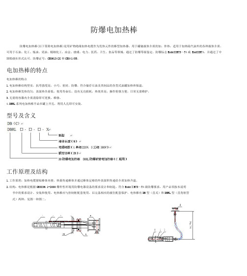
电热棒有DB型(直式)和DBRL型(直角软管式)两种,见图一和图二。
①棒壳②芯管③ 加热电缆④接线盒⑤安装短节①加热电缆②壳体③芯管④接线盒图二10~300KW卧式电加热器外形尺寸(见表一)图二DBRL(直角软管)电热棒结构示意图图二10~300KW卧式电加热器外形尺寸(见表一)DBRL型电加热棒是专门为小型油罐可以在不清洗内部、不在罐壁上重新开孔的条件下能够直接从罐人孔内插入安装而设计的,亦可用于不便在罐侧面开口需在上部安装的储罐(如埋地罐)。
其加热部分在下部水平段,垂直部分为引出线段,高度视用户具体要求确定,接线盒在罐人孔外部连接。
型号及规格注:1、可根据用户要求设计、制作非标尺寸的产品。
用于仪表箱(柜)防冻以及维持温度的防爆电加热器
用于用于仪表仪表仪表箱箱(柜)防冻以及维持温度的防爆电加热器(栾涛栾涛,,INTERTEC 德国英特泰克公司上海代表处德国英特泰克公司上海代表处))一 引言防爆电加热器种类很多,本文仅限于讨论用于仪表箱(柜)防冻以及维持温度的防 爆电加热器。
仪表箱用防爆电加热器主要用于防爆区域中仪表保温箱,分析采样系统的预处理箱,分析柜,分析小屋的防冻以及维持温度。
常见的伴热方式有蒸汽伴热和电伴热,但电伴热是未来的发展趋势。
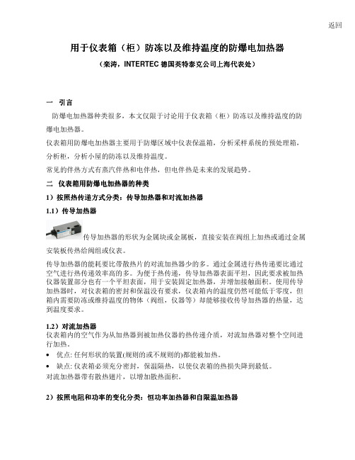
二 仪表箱用防爆电加热器仪表箱用防爆电加热器的种类的种类1)按照热传递方式分类按照热传递方式分类::传导加热器和对流加热器 1.1)传导加热器传导加热器的形状为金属块或金属板,直接安装在阀组上加热或通过金属安装板传热给阀组或仪表。
传导加热器的能耗要比带散热片的对流加热器少的多。
通过金属进行热传递要比通过空气进行热传递效率高的多。
为便于热传递,传导加热器表面平坦,因此要求被加热仪器装置部分也有一个平坦表面,用于安装固定加热器,并增加接触面积。
使用传导加热器时,对仪表箱的密封和保温没有要求,仪表箱内的温度仍然可能低于零度,但箱内需要防冻或维持温度的物体(阀组,仪器等)却能够接收传导加热器的热量,达到温度要求。
1.2)对流加热器仪表箱内的空气作为从加热器到被加热仪器的热传递介质,对流加热器对整个空间进行加热。
• 优点: 任何形状的装置(规则的或不规则的)都能被加热。
• 缺点: 仪表箱必须充分密封,保温隔热,以使仪表箱的热损失降到最低。
对流加热器带有散热翅片,以增加散热面积。
2)按照电阻和功率的变化分类按照电阻和功率的变化分类::恒功率加热器和自限温加热器返回防爆区域温度等级的最高允许温度是T1:450°C ,T2:300°C ,T3:200°C ,T4:135°C ,T5:100°C ,T6:85°C 。
防爆加热器的表面温度不能超出温度等级的限制。
防爆电加热器说明书
博瑞能源中压减压撬100KW中压减压撬防爆加热器使用说明书嘉星燃气设备制造1、主要技术参数2、工作原理与结构概述防爆电加热器由接线箱、电加热管、加热器壳体和温控仪表部分组成,其中接线箱包括了接线盒和电加热管连接板两个部分。
由接线箱和电加热管组成的整体,其机构设计参数符合GB3836.1~3-2000《爆炸性环境用电气设备》的有关规定。
电加热器外形尺寸:发热体为合金电阻电热丝,其材料为Ni80Cr20,与管连接导体一起均装在金属管。
管空隙紧密填充粉状氧化镁无机绝缘填料,发热体相互间及它们与金属管的间距大于2毫米,管连接导体与发热体之间采用压接或硬钎焊连接,并按GB3836.1~3-2000表1和表3规定了的最小电气绝缘及防潮处理。
按GB3836.1~3-2000“爆炸性环境用电气设备”的规定进行形式试验。
接线箱系钢结构件,紧固螺栓数8—M12×50,接合面粗糙度3.2,电缆引入装置采用密封式,密封圈为硅橡胶及丁晴橡胶。
3、使用说明:1)必须与CNG控制柜配套使用,实现联动控制。
2)工作电压不得超过其额定电压的1.0倍,外壳应有效接地。
3)工作环境:0℃ ~ 340℃,无腐蚀气体。
4)先打开电源,液位报警会显示红灯,并且有声音报警,这时加入防冻液直到报警解除后再继续加入10mm左右高的液面,不能一次性加满,这样会造成防冻液因加热后膨胀,而溢出。
5)定期检查电热管表面,如有结炭、污垢,必须除尽后使用。
同时,每隔1年检查一次筒体、腐蚀程度、是否需更换容器及电热管。
6)元件应贮藏在通风干燥处。
7)接线箱的线需套黄蜡管。
8)认真检查电加热器与电加热器配套的电气和仪表控制系统等设备和线路是否完好,确认能否投入使用。
9)定时观察设备、电气、仪表以及控制系统工作是否正常。
10)随时观察三相电流是否平衡。
11)本设备可室安装,若需在室外安装,应置挡雨挡雪设施。
12)每次启动前应对电热管绝缘电阻测量一下,低于2 MΩ时应抽出电热管,放于300℃烘箱中烘干后使用。
防爆电加热器工作原理

防爆电加热器工作原理防爆电加热器是一种广泛应用于石油、化工、电力、冶金等行业的加热设备,它通过电能将电热元件转化为热能,以使加热物体增加温度。
其特殊之处在于,其设计是为了在易燃易爆环境中工作,因此需要具有防爆功能。
本文将详细介绍防爆电加热器的工作原理。
一、防爆电加热器的组成防爆电加热器由三部分组成:外壳、电热元件和控制器。
外壳是防止易燃易爆物质与加热器接触的屏障,具有防爆功能;电热元件是产生热量的核心部分,加热物体通过与电热元件的接触从而被加热;控制器则是控制加热器的加热时间、温度等参数的设备。
二、防爆电加热器的工作原理1、外壳的防爆原理防爆电加热器的外壳采用了一系列的防爆措施,以保证加热器在易燃易爆环境下安全工作。
在外壳设计中,首先采用了防爆结构,通过对外壳的材料、结构进行特别设计,可以防止加热器内部电路中的火花或电弧引起火灾或爆炸。
加热器外壳还设置了特殊的密封结构,以防止易燃易爆物质进入加热器内部。
2、电热元件的工作原理电热元件是防爆电加热器的核心部件,它通过将电能转化为热能,使加热器内的物体升温。
电热元件的工作原理基于“焦耳效应”:当电流通过电热元件时,电阻将使电能转化为热能。
电热元件的设计和制造需要考虑到电路的总阻抗和电流限制,以确保防爆电加热器的正常工作。
由于电热元件的加热功率取决于电流和电压的大小,因此控制加热器的温度需要通过控制电压和电流的大小来实现。
3、控制器的工作原理控制器是防爆电加热器的重要部分,它可以调节加热器的加热时间和温度,以确保加热器在正常工作范围内运行。
控制器的工作原理基于一个反馈回路系统。
当加热器内的温度达到设定值时,温度传感器会将信号反馈给控制器,控制器将根据反馈信号调整加热器的电流和电压,以防止加热器产生过热现象。
在控制器内还设置了安全开关,当加热器电路中出现故障时,可立即切断电源,以确保防爆电加热器的安全工作。
三、总结防爆电加热器作为一种专门应用于易燃易爆环境的加热设备,必须具备防爆功能,以保证在此类场合下的安全工作。
Exheat 工业 FXE 型号防爆封闭式加热器与 FXT 型号温控器安装操作和维护说明书

INSTALLATION OPERATION ANDMAINTENANCE INSTRUCTIONS FOREXHEAT INDUSTRIAL FXE TYPE FLAMEPROOF ENCLOSURE HEATERS&FXTTYPE THERMOSTATSPlease read these instructions thoroughly before installation and ensure they are passed on tothe end-user.1.0GENERAL1.1All work should be carried out by suitable qualified personnel.1.2Carefully remove all protective packaging and visually inspect unit for any transit damage.1.3FXE/FXT’S must be handled with care and stored in dry conditions.1.4CAUTION–These units are designed for industrial use only and additional personnelprotection against contact with hot surfaces may be required in some installations.1.5Before connection ensure that the supply corresponds with that specified on the rating label.1.6Each unit must be protected by a suitably rated over current device.1.7All prevailing rules,regulations and bylaws in force at the time and place of installationmust be observed.1.8The units should be securely fixed in position and all‘end user’made connections checkedfor tightness before energising.1.9Any modification not carried out by Exheat Industrial Ltd or its approved agent willinvalidate certification and warranty.1.10Reference must be made to IEC/EN60079-14&IEC/EN60079-17.1.11All electrical testing must be carried out in a non-hazardous area.2.0INSTALLATION2.1The installer or end user shall ensure that the unit has free and unrestricted airflow.2.2The FXE must only be orientated vertically.2.3The FXT/FXT-I can be orientated vertically or horizontally.2.4The appliances must be securely fitted to an enclosure wall or din rail using the mountingbracket provided.2.5The cable glands and bungs must not be removed under any circumstances.3.0ELECTRICAL SUPPLY CONNECTION3.1The flying lead provided must be terminated using suitable terminals in a certified enclosurein accordance with IEC/EN60079-14(see fig.1).4.0EARTH CONNECTION4.1WARNING–the FX Range MUST BE EARTHED.4.2The external earth connection is located on the bracket and is supplied with an M5fixingnut and bolt.4.3The internal earth connection is within the cable provided and should be terminated in asuitable terminal in accordance with IEC/EN60079-14.5.0OPERATION5.1WARNING–The FX range enclosure heater and thermostat must at no time be coveredduring operation,as this could lead to dangerous overheating.5.2Once energized the enclosure heater will continue to operate until de-energised by anexternal control device(such as the FXT range).5.3The permitted ambient temperature range for operation of the standard FX Range is as fig.2.The end user must ensure that no excursions outside these ambient temperature limits areallowed to occur at any time.6.0MAINTENANCE6.1All prevailing site safety regulations shall be adhered to at all times.6.2Before and whilst any maintenance activity is carried out,it must be ensured that there areno hazardous gases present.6.3Equipment is to be fully isolated from the electrical supply before and whilst any work isbeing carried out.6.4Any damage or faults should be notified to Exheat Industrial Ltd immediately.6.5Any replacement parts required must be obtained directly from Exheat Industrial Ltd.Theuse of any other parts will void any certification and warranty.6.6Reference must be made to IEC/EN60079-17(especially table1)in addition to thefollowing recommendations:6.6.13Monthlya.Generally inspect the equipment for external damage.b.Ensure that the spaces between the element fins remain clear and that the airflowremains unrestricted.7.0Marking and certification reference FX Enclosure Heaters.7.1II2G D(ATEX certified units only)Ex d IIC(Gas)T3or T4GbEx t IIIC(Dust)T200°C or T135°C DbIP6X-50°C<T amb<+80°CDo not open while energisedDo not open in presence of explosive atmosphereLCIE12ATEX3040X(ATEX certified units)IECEx LCI120008X(IECEx certified units)7.2Marking and certification reference FXT Enclosure Thermostats.II2G D(ATEX certified units only)Ex d IIC(Gas)T6GbEx tb IIIC(Dust)T85°C DbIP6X-60°C<T amb<+78°CDo not open while energisedDo not open in presence of explosive atmosphereLCIE12ATEX3086X(ATEX certified units)IECEx LCI120030X(IECEx certified units)Fig.1.Model LIVE NEUTRAL EARTHFXE HEATERS RED/BROWN BLACK/BLUE GREEN AND YELLOWSUPPLY LIVE SWITCHED LIVE NEUTRALS EARTHFXT THERMOSTAT RED/BROWNBLACK/BLUE(SLEEVED TO SUITLIVE)NO NEUTRAL ISREQUIREDGREEN ANDYELLOWFXT–ITHERMOSTAT IN LINE WITH FXE RED/BROWN N/A BLACK/BLUEGREEN ANDYELLOWFig.2.Model Voltage Output Mounting T-Class AmbientFXE30110-120V220-254VAC30W Wall/RailT3T480°C40°CFXE50110-120V220-254VAC50W Wall/RailT3T480°C40°CFXE75110-120V220-254VAC75W Wall/Rail T360°CFXE100110-120V220-254VAC100W Wall/Rail T360°CFXT110-120V220-250VAC1.3A MAXALLOWEDWall/Rail T678°CFXT-I110-120V220-250VAC1.3A MAXALLOWEDWall/Rail T678°CThis Page Intentionally Left BlankThis Page Intentionally Left Blank。
防爆电加热器的加热方式有哪些?
防爆电加热器的加热方式有哪些?1、电阻加热:这主要是利用电流的焦耳效应将电能转变成热能以加热物体。
因被加热物体和发热元件分成两部分,因此被加热物体的种类一般不受限制且操作简便。
2、感应加热:是利用导体处于交变电磁场中产生感应电流(涡流)所形成的热效应使导体本身发热。
此加热特点可以对物体进行整体均匀加热和表层加热,还可进行任意局部加热。
3、电弧加热:利用电弧产生的高温加热物体。
电弧柱的温度可达3000~6000K,适于金属的高温熔炼。
4、电子束加热:利用在电场作用下高速运动的电子轰击物体表面,使之被加热。
5、电红外线加热:利用红外线辐射物体,物体吸收红外线后,将辐射能转变为热能而被加热。
它具有较强的穿透能力,易于被物体吸收,红外线加热应用发展很快。
6、介质加热:利用高频电场对绝缘材料进行加热。
它加热速度快,热效率高,而且加热均匀。
防爆电加热器的防雷设备是使用其高出被维护物的杰出位置,把雷引向本身,然后经过引下线和接地设备,把雷电流泄入大地。
常见的防爆电加热器的防雷设备有:避雷针、避雷网、避雷带、避雷线、避雷器等。
依据维护的目标不一样,接闪器可选用避雷针、避雷线、避雷网或避雷带。
避雷针首要用于建筑物和构筑物的维护;避雷线首要作为电力线路的维护;避雷网和避雷带首要用于建筑物的维护;避雷器是避免雷电侵入波的一种维护设备。
(2)电离防爆电加热器的防雷是一种新技术,它由顶部的电离设备,地下的地电流搜集设备及连接线组成。
电离防爆电加热器的防雷设备是使用雷云的感应效果,或选用放射性元素在电离设备邻近构成强电场,使空气电离,发作向雷云移动的离子流。
这样,雷云所带电荷便得以缓慢中和并走漏,从而使空气电场强度不超越空气的击穿强度,消除落雷条件,按捺雷击发作。
(3)可燃、易燃液体贮罐的防爆电加热器的防雷办法是:1)金属油罐的防爆电加热器的防雷:由于金属油罐本身就有着杰出的屏蔽功能,只需油罐顶板有满足的厚度,使用本身的维护是能够满足要求的。
EXHEAT 工业有限公司 FWD 和 FWD-T 型号防爆空气加热器说明书
INSTALLATION OPERATION ANDMAINTENANCE INSTRUCTIONS FOR EXHEAT INDUSTRIAL LTD. FWD & FWD-T TYPE FLAMEPROOF AIR WARMERSPlease read these instructions thoroughly before installation and ensure theyare passed on to the end-userCONTENTS1.0 GENERAL 32.0 STORAGE 33.0 PRE INSTALLATION INSPECTION AND CHECKS 44.0 INSTALLATION 45.0 ELECTRICAL SUPPLY CONNECTION 56.0 EARTH CONNECTION 57.0 OPERATION 58.0 MAINTENANCE 69.0 MARKING 710.0 CERTIFICATION 7APPENDIX A – WIRING DIAGRAM 8 APPENDIX B – ATEX HAZARDOUS AREA CERTIFICATETo maintain the equipment warranty and the Hazardous Area Certification, the instructions contained within this manual must be complied with in full.1.0 GENERAL1.1 All work should be carried out by suitable qualified personnel.1.2 Carefully remove all protective packaging and visually inspect unit for any transit damage.1.3 Heaters must be handled with care and stored in dry conditions.1.4 CAUTION – Air warmers over 1m long are HEAVY and must be handled appropriately.1.5 CAUTION – These heaters are designed for industrial use only, and additional personnelprotection against contact with hot surfaces may be required in some installations.1.6 Before connection ensure that the supply corresponds with that specified on the rating label.1.7 Ensure that the sizes and types of cables to be used are suitably rated for the load andtemperature of the unit.1.8 Each heater must be protected by a suitably rated over current device.1.9 All prevailing rules, regulations and bylaws in force at the time and place of installation mustbe observed.1.10 The heater should be securely fixed in position and all terminal connections checked fortightness before energising.1.11 Any modification not carried out by Exheat Industrial Ltd will invalidate certification andwarranty.1.12 If you are installing a hazardous area heater. Reference must be made to EN 60079-17 & IEC1241-1-2.1.13 All electrical testing must be carried out in a non-hazardous area.1.14 Precautions must be taken to prevent damage to machined surfaces and threads offlameproof enclosure.1.15 The FWD-T model variant includes a factory fitted integral externally adjustable air sensingthermostat. The MAXIMUM setting is to be no more than +25°C (approx. between 2 & 3 on the scale)1.16 Ensure that any special conditions for safe use detailed on the hazardous area certificationare complied with.2.0 STORAGE2.1 Store the equipment in an inside location that is dry, clean and well ventilated.2.2 Suitable preservation materials, such as silica gel bags or equivalent, have been placedinside the packaging. Additionally, spare silica gel bags, or equivalent, can be supplied bycontacting Exheat Industrial Ltd.2.3 If the equipment is stored beyond 3 months, ensure that preservation materials are replaced.2.4 CAUTION – It is the client’s responsibility to ensure that, if the terminal enclosure is openedprior to installation, these bags are checked and replaced if necessary. When refitting terminal enclosure lid please ensure the gaskets or O-rings are not damaged or moved in any way and for the HFT & AFT thermostats please refer to 5.9 below.2.5 CAUTION – The following preservation instructions must be adhered to. Failure to do socould result in the equipment warranty being invalidated:•Store the equipment at between 0°C and +50°C.•Ensure that the equipment is not subjected to direct sunlight at ambient temperatures above 30°C.3.0 PRE INSTALLATION INSPECTION AND CHECKS3.1 Each heater and thermostat is manufactured to the highest standard with great care andquality materials. All the goods are thoroughly inspected and tested before leaving themanufacturing plant. They must be handled with care during storage and installation. Before the installation starts it is advised that the heater is checked to ensure the insulationresistance reading is above 2MΩ per element at 500 volts dc.Should the heater fail this test, isolate the power and control circuits (if installed), and followthe steps below:•Fill the terminal box with silica gel bags, and replace the terminal box lid.•Leave for 24hrs to draw any moisture out of the heater elements.•If you have a heated blanket, place this over the heater elements to help with the drying.Heater blankets are available to purchase from http://www.exheat-/contact/enquiry• If the insulation resistance has not been raised to a sufficient level after 24hrs, repeat the process above with replacement gel bags.•Should the above not raise the insulation resistance to the required level please contact the technical help on our website. /contact/support3.2Insulation Resistance (Megger)3.2.1 The ‘Megger’ should be applied between the phases and earth. A reading of greater than2MΩ at 500 volts dc should be recorded. Should the whole heater be below this value eachelement would need to be checked to ascertain which one was low in resistance.3.2.2 Use the continuity (Ohms) setting on the elements and check the resistance of each elementmatches or is approximately equal to the results as per the electrical test cert that would have been sent with the heater.4.0 INSTALLATION4.1 Carefully remove the packaging from each item and check for damage. Immediately reportany damage to Exheat Industrial Ltd.4.2 The heater should be securely fixed in position and all terminal connections checked fortightness before energising.4.3 The appliance must be securely fitted to a wall or floor using only the brackets provided.4.4 The installer or end user shall ensure that the unit has free and unrestricted airflow to allownatural convection to occur.4.5 Orientation of heater must be strictly adhered to. The heater tube must remain horizontal at alltimes whilst energised.4.6 The installer or end user shall ensure that the unit has free and unrestricted air flow to allownatural convection to occur at all times. DO NOT COVER the heater and do not allowanything to rest on or against it. This could lead to dangerous overheating and will invalidate the hazardous area certification.4.7 At no time is the ambient temperature to be allowed to rise above 40°C (T3 & T4 Variants) Or60°C (T2 Variants). This can be achieved by the use of Exheat Industrial Ltd Integral (ifoption available) or separate flameproof air thermostats (HFT & AFT).4.8 Threaded (FWD) or spigot (FWD-T) cover flame path surfaces must be checked to ensurethat they are undamaged and the ‘O’ ring must be fully located in its groove before re-fitting.5.0 ELECTRICAL SUPPLY CONNECTION5.1 Refer to wiring diagrams in APPENDIX A.5.2 The cable entries in the FWD & FWD-T Ranges are positioned to the side and bottom of theterminal boxes. No additional cable entries are to be made within any of the terminal boxes.Only Exheat Industrial Ltd personnel can facilitate this.5.3 The cables must enter the FWD & FWD-T heaters via the terminal box cable entries using Exd cable glands and IP Washers (If Required). All cable glands are to be suitable for therating and size of the supply cables.5.4 Before connection ensure that the supply corresponds with that specified on the rating label.5.5 Ensure that the sizes and types of cables to be used are suitably rated for the load andtemperature of the unit.5.6 Each heater must be protected by a suitably rated over current device and earth leakagecircuit breaker device. See section 5 below for earthing details.5.7 The cables must enter the heater terminal box via suitably certified cable glands and IPwashers (not supplied) and be fitted by a qualified person. Any unused entries should remain plugged with the factory fitted certified Ex d plugs (if installed) or with suitably rated plugs and IP washers.5.8 FWD only: the cover of the FWD terminal box is unscrewed after slackening a locking grubscrew using a 3mm A/F hex key. When re-fitting ensure that the ‘O’ ring seal is in goodcondition and correctly located. The cover threads MUST be kept clean and free from anydebris at all times.5.9 FWD-T only: the cover of the FWD-T terminal box is opened after the three socket headscrews have been removed. When re-fitting ensure that the ‘O’ ring seal is in good condition and correctly located. The cover spigot mating faces MUST be kept clean and free from any debris at all times.5.10 FWD-T only: the terminal box of the FWD-T may be rotated as necessary for alignmentpurposes only while the cover is removed. Slacken the 3-off grub screws in the locking ring inside the base of the terminal box and then rotate the locking ring anti-clockwise sufficiently to allow re-alignment of the terminal box. The locking ring is tightened by rotating clockwise.The 3-off grub screws in the ring must be re-tightened before the terminal box cover is re-fitted5.11 After re-fitting the lids on the FWD-T, the gap between the cover and the body must bechecked to ensure that it does not exceed 0.15mm.5.12 The installer or end user must connect to the Exheat Industrial Ltd supplied terminals withinthe terminal box - DO NOT connect to or disturb factory fitted wiring.5.13 WARNING – Silica gel bags must be removed before the heater is energised.6.0 EARTH CONNECTION6.1WARNING – the heater MUST BE EARTHED.6.2 The external earth connection is located on the outside of the terminal box.6.3 The internal earth connection is via a pillar or screw (FWD-T) inside the terminal box.7.0 OPERATION7.1 Heat is generated by means of electric heating elements. Once energized the air warmerswill continue to operate until de-energized by an external (or integral) air thermostat.7.2 To adjust the temperature settings on an integral thermostat (FWD-T), rotate the adjustablecontrol (by means of a large flat screwdriver) clockwise to increase the desired set-point oranti-clockwise to reduce the set-point. The MAXIMUM setting is to be no more than +25°C (approx. between 2 & 3 on the scale)7.3 The permitted ambient temperature range for operation of the standard FWD Air Warmers is -60°C ≤ T amb≤ +40°C. A special high ambient version (up to +60°C) is available, identified by marking of the extended ambient temperature range. The end user must ensure that noexcursions outside these ambient temperature limits are allowed to occur at any time.7.5 CAUTION – Check that the voltage on the heater nameplate is compatible with the mainssupply being used before energising the heater.8.0 MAINTENANCE8.1 All prevailing site safety regulations shall be adhered to at all times.8.2 Equipment shall be checked regularly for any dust accumulation which must be removed fromall surfaces.8.3 Before and whilst any maintenance activity is carried out, it must be ensured that there are nohazardous gases or dusts present.8.4 Equipment is to be fully isolated from the electrical supply before and whilst any work is beingcarried out.8.5 Any damage or faults should be notified to Exheat Industrial Ltd immediately.8.6 Any replacement parts required must be obtained directly from Exheat Industrial Ltd. The useof any other parts will void any certification and warranty.8.7 Equipment is certified for use in a hazardous area and reference should be made toEN60079-17 (especially table 1) & IEC 1241-1-2 in addition to the followingrecommendations..8.7.1 3 Monthlya. Generally inspect the equipment for external damage.b. Ensure that the spaces between the element fins remain clear and that the airflowremains unrestricted.8.6.2 6 Monthlya. Isolate the electrical supply and remove the cover. (As 5.8 or 5.9)b. Internals should be clean and dry.c. Ensure terminals are intact and secure.d. Heating element insulation resistance to be at least 2 M-ohm. Please refer to section 3.0for further information)e. Refit cover with new ‘O’ ring if required (note – this must be secured in place using RTVsealant supplied with the replacement ‘o’-ring. (As 5.8 to 5.13)f. Earth continuity must be maintained between all earth points and main structure.8.7.3 Annuallya. Carry out 3 monthly and 6 monthly checks as above.b. Check for element failure or low insulation resistance, as section 2.8.8 If equipment is being left unused for a period greater than 3 months, carry out 6 monthlymaintenance before energizing.8.9 Removal and Replacement of Ceramic Core Type Heating Element.8.9.1 Request the new core and the relevant “Clients Works Instruction” to facilitate the removaland replacement of a new core.9.0 Marking and certification reference9.1 II 2 G D (ATEX certified units only)Ex d IIC T4, T3 or T2Ex t IIIC T***°C Db IP66 (T135, T200 or T300ºC)Do not open while energisedDo not open in presence of explosive atmosphereIf the temperature at the conduit entry exceeds 70ºC high temperature cable must be used LCIE 04 ATEX 6016 X (ATEX certified units)IECEx LCI 07.0005X (IECEx certified units)APPENDIX AWIRING DIAGRAM FOR FWD TYPE (DIRECT CONNECTION TO ELEMENT)APPENDIX A (Con’t)WIRING DIAGRAM FOR FWD-T TYPEAPPENDIX B - CERTIFICATIONThis Page Intentionally Left BlankThis Page Intentionally Left Blank12。
WDDQ-380-400-Ex电加热器使用说明书
防爆电加热器使用说明书一、技术参数:1.产品型号:WDDQ-380-400-Ex2.总外形尺寸:总高度约5300mm直径700mm3.型式:管式电加热:采用Φ30直型电加热管。
展开长度:4350mm;发热区长度:约3900mm;非发热区长度:450mm。
用螺母压紧紫铜垫片密封,方便拆卸。
4.设计压力:4.5MPa最高工作压力:4.05MPa5.设计温度:270℃工作温度:210℃6.加热介质:CO27.工作电压:380V,50Hz,8.工作功率:9.5KW/支9.发热元件:高温镍铬合金电阻丝10.电热管材质:SUS30411.法兰材质:SUS30403不锈钢12.接线腔室:防爆型材质:Q23513.接线方式:△三角型接法(分四组,第一、三组是120KW,第二、四组是80KW)14.防爆等级:dIIBT215.防护等级:IP65,绝缘等级:B16.测温元件:PT100,量程:-50~400℃二、工作流程:加热器发热部分完全浸入在被加热介质里,通电后电热管内的电阻丝就会产生热量并散发到电热管表面,将热量传导给介质。
从而使介质获得满足工艺要求的温度。
三、安装、使用说明1.电加热管设备安装使用前应贮藏在通风干燥处,不得受潮。
2.安装工作环境:-20℃~+40℃,无灰尘、无污染、无腐蚀性气体场所。
3.通电运行前,认真检查电加热管与之配套的电气、仪表、温控系统各设备间线路接线是否连接完好,各接线是否紧固牢靠,内外壳应有效接地。
4.检测电加热管的绝缘电阻,确认合格后方可使用。
5.电加热管安装完毕后,请在气体流通的情况下再通电加热,检查压力及流量,观察内部温度升高情况,在无压力无流通时通电加热极易烧毁电加热管,此类情况生产方不予质保或退换!6.加热器运行前,必须检查电加热器内部气体是否流通,确认无误方可投入使用。
7.电加热管工作时,电压不得超过其额定值的1.1倍。
8.设备初运行时,必须有专人定时观察设备、电气、仪表及控制系统工作是否正常,如发现有异常,应立即停止设备运行。
Ruffneck FX6系列爆炸防护电气空气加热器产品说明书
Arctic Duty MotorSpare fuse locatedin convenient holderJunctionboxFigure 16Ruffneck™Notes* Exceeds the 48 amp circuit limit of NEC 424-22. DS not available for these units.**480 V: 1-phase units are certified for Class I, Div. 1, Group D and Class II, Div.1 Groups F & G1. Minimum conductor size for 86˚F (30˚C) ambient. Derate conductor forambient temperature. Use minimum 194˚F (90˚C) insulation.2. Heater is functioning normally if at rated voltage the amp draw iswithin 10% of the value in this table.3. Operation at lower voltages will result in reduced heat output and ampdraw.4. Add “T” to model number when adding a built-in thermostat.5. Add “D” to model number when adding a built-in disconnect switch.6. Add “P” to model number when adding a built-in pilot light.7. Add “U” to model number for units with continuous fan option.8. Add “A” to model number for units with stainless steel cabinet.9. Add “L” for large junction box.10. Add "C" to model number for units with Heresite coating.For installation and model coding, see page C10.Consult Terms & Conditions of Sale or FX6 Owner’s Manual for warranty information.7Ruffneck™8Ruffneck™E x p l o s i o n -P r o o f E l e c t r i c A i r H e a t e r s –F X 6 S e r i e sInstallation Conditions࢞The FX6 Series Electric Air Heaters are for dry indoor use only. Donot immerse in water. Do not store or use in areas exposed to rain or snow.࢞The FX6 heaters are to be used only in atmospheres having anignition temperature higher than 329°F (165°C).࢞Altitude restrictions apply, see General Specifications, page 11࢞Heaters should be connected to a fixed power supply and mustbe permanently mounted in a level, upright position during operation.࢞Read and be aware of the terms of our Warranty located in theowner’s manual.࢞For more information please refer to owner's manual.* Exceeds the 48 amp circuit limit of NEC 424-22. DS not available for these units.**480 V: 1-phase units are certified for Class I, Div. 1, Group D and Class II, Div. 1 Groups F & G 1. Minimum conductor size for 86˚F (30˚C) ambient. Derate conductor for ambient temperature. Use minimum 194˚F (90˚C) insulation.2. Heater is functioning normally if at rated voltage the amp draw is within 10% of the value in this table.3.Operation at lower voltages will result in reduced heat output and amp draw.4. Add “T” to model number when adding a built-in thermostat.5. Add “D” to model number when adding a built-in disconnect switch.6. Add “P” to model number when adding a built-in pilot light.7. Add “U” to model number for units with continuous fan option.8. Add “A” to model number for units with stainless steel cabinet.9.Add “L” for large junction box.10. Add "C" to model number for units with Heresite coating.ote: N*For specifications common to all FX6 models, see General Specifications, page 11. Weights are an approximate maximum. Manufacturer reserves the right to replace motors with suitable alternates.9 Ruffneck™elEfoorP-noisolpxE10Ruffneck™11Ruffneck™ FX6 Series – Explosion-Proof Electric Air HeatersGeneral Specifications1. Hazardous Location RatingClass I, Divisions 1 and 2; Groups C and D; Class II, Groups E, F and G;Class II Division 2, Groups F & G; Class I Zones 1 & 2, Groups IIA & IIBTemperature Code T3B [329°F (165°C)]*2. Enclosures NEMA Type 7 & 9. For dry, indoor use only. Do not immerse in water. Do not store or use in areas exposed to rain or snow3. Motor Type Explosion-proof. Thermally protected. Permanently lubricated ball bearings.4. Fan Aluminum blade. Steel spider and hub with 5/8" (15.875 mm) bore5. Fan Guard Split design with close wire spacing. 1/4" (6.3 mm) diameter probe will not enter 6. Mounting Holes Two 9/16". (14.3 mm) diameter holes at top7. Heating Elements Three long-life, low watt-density, high grade metal sheathed elements 8. Temperature High-Limit Automatic reset type, snap-action bimetal, open on temperature rise. Rated 100,000 cycles at 10 amps, handles 0.128 amps 9. Control Circuit 120 V, 0.128 amps, 15 VA. (Grounded)10. Safety Protection Circuit Snap action bimetal switch, rated for 100,000 cycles at 10 amps. Part of secondary thermal protection circuit with dedicated contactor. Independent of main control circuit.11. Slim Junction Box 10.25" (230 mm) x 8.00" (180 mm) x 6.75" (172 mm) 12. Optional Built-in Thermostat Explosion-proof. 36°F to 82°F (2°C to 28°C)13. Optional Built-in Disconnect Switch DS for use only on heaters with total current not exceeding 48 amps. Lockout handle accepts 1/4" diameter padlock shackle 14. Optional Pilot Light Indicates heat-on cycle15. Control TransformerMulti-tap primary, 120 V secondary, 50 VA16. Contactors75 amps. Rated for 1,000,000 mechanical operations. 120 V, 15 VA coil (separately fuse-protected)17. Heat Transfer Fluid Proprietary heat transfer fluid18. Cabinet Material 12 ga. (0.104") (2.60 mm) steel. Epoxy coated with five-stage pretreatment, including iron phosphate. Optional stainless steel.19. CoreSteel with integral aluminum fins, vacuum charged and hermetically sealed 20. C onduit Material Heavy walled, 0.122" (3.1 mm) steel21. Overpressure Protection Preset 100 psig (690 kPa) pressure relief valve, no field serviceable parts. Preset 300 PSIG (2070 KPa) rupture disk, no field servicable parts.22. O perational Temperature Limitations -58ºF to 104ºF (-50ºC to 40ºC)23. S torage Limitations-58°F to 176°F (-50°C to 80°C). Do not immerse in water. Do not expose to rain or snow.THS2053-0922。
XEU1防爆电加热器业主手册说明书
235730Forced-Air Heater for Hazardous LocationsClass I, Division 1 & 2, Groups C & D Class II, Division 1 & 2, Groups F & G Temperature Code T3B (3kW/35kW = T3A) ————————————————————————————————————-Class I, Zone 1 & 2 , Groups IIA & IIB, T3WARNING!Please adhere to all instructions published in this manual. Failure to do so may be dangerous and may void your warranty.Note: XEU1 heaters must not be exposed to rain or snow. This applies to installed & stored heaters.The XEU1 heater should not be modified in any way.Part No. XEU1-OM-HPrinted in CanadaElectric Forced-Air Explosion-Proof Heater Owner’s Manual, Version: XEU1-OM-HThis manual covers installation, maintenance,repair, and replacement parts.Full Model Code & Option SequenceXEU1 Model Coding on Data PlateOption CodesModel CodeXEU1 Physical DimensionsXEU1 Specifications By Model SizeApprovalsClassifications ————————————————————————————————————————Class I, Zone 1 & 2, Groups IIA & IIB, T3Temperature Code Division System - T3B 165°C (329°F); [3kW/35kW = T3A 180°C (356°F)] Zone System - T3 200°C (392°F)CabinetCabinet Material 14-gauge (0.075 in.) (1.9 mm) steel. Yellow epoxy/polyester powder coated with five-stage pretreatment, including iron phosphate.Fan GuardSplit design with close wire spacing. A 3/8 in. (9.5 mm)diameter probe will not enter. Black polyester powder coated. Louver BladesAnodized extruded aluminum.Conduit Materials & Fittings Plated steel and aluminum alloy for corrosion resistance.Fasteners Zinc plated steel for corrosion resistance.EnclosuresCast aluminum (non-copper alloy) NEMA Type 7 & 9 with O-ring. Mounting Holes9/16” diameter holes – Four located on the top face of heater.Motor/FanMotor Type Explosion-proof, thermally protected, 1725 RPM permanently lubricated ball bearing type with 56 frame and “easy-off” fan blade replacement feature. FanThree-blade aluminum, steel spider and hub with 5/8 in. bore Heating Elements Long-life, low watt-density, high grade metal-sheathed elements. Model XEU1-12 XEU1-16 XEU1-20 Fan Diameter in. (mm) 12 (304.8) 16 (406.4) 20 (508.0) Nominal kW 3 7.5 10 15 20 25 30 35 Air Delivery CFM 350 600 800 1200 17002100 3000 m 3/hr 595 1019 1359 2039 2888 3568 5097 Approx. Air Velocity FPM 422 718 958 808 1145 916 1309 m/s 2.1 3.6 4.9 4.1 5.8 4.6 6.6 Approx. Horizontal Air Throw ft 13 22 30 33 4641 61 m 3.9 6.7 9.1 10.1 14.012.5 18.6Motor Power HP (Watts) ¼ (186) ¼ (186)½ (373) Maximum Mounting Height ft 7 7.5 9.5 10 1112 15 (to underside of heater) m 2.1 2.3 2.9 3.0 3.43.6 Approx. Net Weight (without disconnect)Lbs (kg) (with disconnect) 129 (58.5) 133 (60.3) 161 (73.0) 192 (87.1) 142 (64.4) 146 (66.2) 174 (78.9) 205 (92.9)Approx. Shipping Weight (without disconnect) Lbs (kg) (with disconnect) 188 (85.3) 192 (87.1)224 (101.6) 261 (118.4) 201 (91.2)205 (93.0)237 (107.5)274 (124.3)4.65 400 680 479 2.4 15 4.67 2.1manual reset type. The heater is not to be operated with the high-limit cutouts disabled or disconnected from the control circuit.Keep all electrical enclosure covers tightly closed and secured with all bolts and threads. Cover joints must be clean before replacing covers. Keep away from rain or snow. Heater is for dry indoor use only.ll unused threaded openings not used for supply wiring or remote mount room thermostat must be fitted with threaded plugs approved for use in hazardous locations.he heat exchanger is a factory vacuum-sealed unit. Do not attempt to loosen or tighten the vacuum plug or pressure relief device. A loss of vacuum could cause nuisance tripping of the thermal cutouts or high pressures which will cause the relief device to actuate with an accompanying loss of fluid.he heat exchanger is filled with a mixture of water and inhibited ethylene glycol which is poisonous Contact with the fluid at operating temperatures may produce a burn hazard. Suggested first aid consists of flushing eyes with plenty of water and to wash off skin in flowing water or shower. If any fluid leakage occurs from the heater, disconnect it from the power supply and have the heat exchanger replaced with a factory supplied unit.eater must be kept clean. When operating in a dirty environment, regularly clean the fin tubes, fan, and fan guard. Refer to recommended maintenance procedures.— INSTALLATION —MechanicalLocationPlease follow guidelines below for optimum heating results:1. Do not install heaters such that airflow is blocked or impeded by equipment or walls.2. For occupant comfort, position heaters so that air discharge is directed across areas of highest heat loss, such as doors, windows, and outside walls.3. For large areas, arrange heaters such that the air discharge of one heater is directed towards the inlet of the next heater. This sets up a rotational airflow with air circulation in the central area of the building.4. For equipment freeze protection, direct air discharge at equipment.5. For large workshops or warehouses it may be acceptable to use fewer, larger heaters.6. Locate remote mount room thermostat on interior partition walls or posts away from cold drafts, internal heat sources, and away from heater discharge air streams.Mounting1. A variety of mounting brackets are available from the factory toaid in installation.2. If using mounting hardware or a supporting structure not supplied by the factory, the unit should be suspended through the four 9/16 in. (14 mm) mounting holes on top of the unit with Grade 5, 1/2 in. UNC bolts. Lock washers should be used on all mounting nuts and bolts to ensure they don’t vibrate or work loose due to fan vibration or other vibration transmitted to the heater. If in doubt consult factory.3. It is essential that adequate structural support be provided for installation.support the heaters weight , provide sufficient stiffness toprevent excessive vibration, and withstand all probable abusive situations such as transportable installations where truck off-loading impacts, etc. may occur. Refer to table on Page 3, XEU1 Specifications by Model Size, for heater net weights.Mounting Heights and Clearances1. To ensure that warm air reaches the floor observe the recommended maximum mounting heights in table on Page 3, XEU1 Specifications by Model Size. Heaters may be mounted at higher elevations and still provide warm air at floor level however, the maximum mounting elevation at which this occurs depends on location and operational conditions.2. Louvers may be adjusted to provide greater downward deflection of the discharge air. However, louversmust not be set less than 30 degrees of the closed position.Heater Fan SizeHeater may be supplied with a factory installed integral roomthermostat with lockable temperature dial (See Figure 1). If aremote explosion-proof room thermostat is used, connection is to be made via the 3/4" NPT entry (entry “B” listed in the“Enclosure Entries” table on page 4). Refer to the thermostatinstallation manual and the wiring diagrams on page 9 to connect the remote thermostat. Refer to wiring diagram on Page 9 to ensure that all connectionsare as required and securely fastened. 10. For heaters supplied with a factory installed integral disconnectswitch (See Figure 1), field wiring is as follows:Remove the Disconnect cover assembly from the base byremoving the six (6) cover bolts. Set the cover assembly aside. CAUTION: Damaging the mating surfaces of the enclosure could destroy the flame path and jeopardize the integrity of the flame proof enclosure.Supply conductors and ground conductor pass through the 1in. NPT rigid conduit opening located on the top or bottom of Disconnect Enclosure. Supply conductors to be wired to DIN rail mounted Disconnect Switch inside. Ground conductor to be wired to Ground Lug fastened to inside of Disconnect Enclosure. Refer to wiring diagram on Page 9.Attach cover to the enclosure using the six (6) bolts. TightenXEU1-12-050-208360- 5 208 3 15.0 18.7 20 XEU1-12-050-240360- 5 240 3 13.1 16.4 20 XEU1-12-050-480360- 5 480 3 6.6 8.2 15 XEU1-12-050-600360- 5600 35.26.6 15 XEU1-12-075-208160-7.5 208 1 38.4 47.9 50 XEU1-12-075-240160- 7.5 240 1 33.7 42.1 45 XEU1-12-075-208360- 7.5 208 3 21.9 27.4 30 XEU1-12-075-240360- 7.5 240 3 19.1 23.9 25 XEU1-12-075-480360- 7.5 480 3 9.6 12.0 15 XEU1-12-075-600360- 7.5 600 3 7.6 9.6 15 XEU1-12-100-240160- 10 240 1 44.1 55.1 60 XEU1-12-100-208360- 10 208 3 28.9 36.1 40 XEU1-12-100-240360- 10 240 3 25.2 31.4 35 XEU1-12-100-480360- 10 480 3 12.6 15.7 20 XEU1-12-100-600360- 10 600 3 10.1 12.6 15 XEU1-16-150-208360- 15 208 3 42.7 53.4 60 Figure 1— Repair and Replacement —Heat Exchanger Replacement (See Page 10 for assembly diagram)The heat exchanger core assembly has been fluid filled and vacuum sealed at the factory and is not field repairable. Replacement heat exchanger core assemblies are available from the factory and are inspected and electrically tested for correct heat output and proper operation of the high-limits.1. Explosion/Electric Shock Hazard. Disconnect heater from power supply or fuse box before opening enclosures orservicing heater. Lock the switch in the “OFF” (open) position and/or tag the switch to prevent unexpected power application.2. To prevent burn hazard, be sure heat exchanger and fluid has been allowed to cool before proceeding.3. Remove cabinet bottom panel, element housing cover, element enclosure cover, & control enclosure cover.4. From the control enclosure, disconnect two high-limit wires from printed circuit board terminal block marked 3 & 4 anddisconnect three output heating element wires from contactor terminals marked T1, T2, & T3.5. Slightly loosen all cabinet bolts and louver screws to prevent heat exchanger from binding.6. The heat exchanger is secured by three 1/4 in. bolts on the right-side cabinet panel (when facing front of heater) andone 1/4 in. bolt located on the left side of heater. On 3 - 10 kW models the left-side bolt is located at the top right-hand foot of control enclosure. On 15 - 35 kW models the left-side bolt is located above the control enclosure. With an assistant supporting the weight of the heat exchanger remove these 4 bolts. Carefully lower the heat exchanger from the cabinet.7. Reverse the above procedure when installing a new heat exchanger.Temperature High-Limit Replacement (See Page 10 for assembly diagram)This heat-exchanger includes one automatic reset & one manual reset temperature high-limit that are wired in series. The automatic reset high-limit is rated for 100,000 cycles and is for a temporary failure condition. Continuous nuisance tripping of the automatic reset is generally not the fault of the high-limit but is usually caused by incorrect operating voltage, blocked air inlet or outlet, fan/motor malfunction, high ambient temperatures, excessively dirty heat exchanger or leaking heat exchanger. Care should be taken to determine the exact reason that the automatic reset high-limit control tripped so the problem can be resolved immediately. The automatic reset high-limit normally fails in the open position, however, it can also fail closed.If the automatic reset fails in the open position the heater will not function and the high-limit should be replaced. The occurrence of the manual reset high-limit control to trip is an abnormal condition and indicates that the automatic reset high-limit has failed in the closed position. If this occurs remove the heater from service immediately and replace both the automatic and manual reset high-limits. Determine the exact reason that the automatic reset high-limit control tripped so the problem can be resolved immediately. If the manual reset high-limit shuts down the heater it will have to be reset by pressing on the small reset button protruding from the center of the high-limit device.1. De-energize the heater electrical supply circuit.2. Remove element housing cover, and element enclosure cover.3. Remove the wires from both the auto and manual high limits, make note of the wire position and connection points.4. Remove automatic reset high-limit assembly by unscrewing (counter-clockwise), clean the inside of the thermowell. Aclean thermowell ensures good thermal contact.5. Remove manual reset high-limit assembly by removing the two retaining screws, clean any residual heat sinkcompound from the housing surface. A clean housing surface ensures good thermal contact6. Replace both the auto and manual high-limits with factory supplied units only. Apply heat sink compound to the bottomof the auto high-limit, and screw into thermowell. Apply heat sink compound to the bottom of the manual high-limit and attach to the housing using the two screws.7. Re-attach the wires to both high limits.8. Replace element housing cover, and element enclosure cover.9. Energize the heater electrical supply circuit and let run for 15 minutes to reach a stable operating temperature.10. If heater operation appears to be normal, place unit into service.Fan, Fan Guard or Motor Replacement (See Page 10 for assembly diagram)The motor is a sealed unit that requires no lubrication. If the motor is defective, it must be replaced with an original factory supplied motor.1. Remove four bolts holding motor to the motor mount, and covers from junction box and control enclosure.On units with an integral room thermostat, remove 4 bolts on front face of thermostat enclosure .2. Detach and remove two-piece fan guard assembly by removing top and bottom screws that attach the fanguard to the cabinet.3. Loosen fan blade set screw and remove fan blade from end of motor shaft leaving it in fan panel opening.4. Unscrew the expansion union fitting between motor and motor enclosure (or integral thermostat enclosure).5. If replacing motor , note wire connections for future reference and cut all wires leading to the motor closeto the terminations. All motor wires are permanently marked according to the nameplate on the motor. Lift the motor assembly off the motor mount .6. If replacing fan blade only do not cut any wires and move the motor assembly back sufficient to assist fanblade removal.7. To reassemble, place fan blade inside fan panel opening and then place motor onto motor mount. Slip fanblade onto motor shaft and ensure fan hub is flush with end of motor shaft. Tighten set screw to 150 in-lbs torque.8. Fasten the two-piece fan guards to the cabinet.9. Tighten conduit fittings between motor and motor enclosure (or integral thermostat enclosure). Center fan in fan-panel opening and leave approximately 1/16” to 3/16” (1.6 to 4.8 mm) gap between motor face and fan guard. 10. Bolt motor to motor mount, tighten nuts to 250 in-lbs torque. Manually spin the fan blade to ensure it rotates freely before reconnecting heater to power supply. Fan must rotate counterclockwise when viewed from rear of heater. Contactor (See Page 10 for assembly diagram)1. Loosen, but do not remove contactor mounting screws. Slide contactor off mounting screws.2.Replace with a factory supplied contactor of the same rating.Transformer (See Page 10 for assembly diagram)1. Replace with a factory supplied transformer of the same rating.2.On the new transformer, select primary wires to match heater voltage. Ensure that the correct transform-er secondary lead is grounded (see Page 9 wiring diagram). Individually terminate all unused wires using closed end connections.Printed Circuit Board (See Page 10 for assembly diagram)1.Replace with a factory supplied printed circuit board (see Page 9 wiring diagram).Thermal Delay Fuse (See Page 10 for assembly diagram)1. Replace fuse with one of the same type and rating as indicated on printed circuit board or refer to parts list. An extra fuse should be stored in the clips marked “SPARE”.— Repair and Replacement, Continued —Torque SettingsItem Torque (in-lbs) Fan blade set screw (1 only) 150 5/16 - 18 UNC motor nuts 250 5/16 - 18 UNC motor mount bolts 2501/4 - 20 UNC fan panel bolts 100 1/4 - 20 UNC fan guard self tapping screws 100 #10 - 24 UNC louver blade screws 28Wiring Diagram for Standard Fan Operation Wiring Diagram for Continuous Fan OperationOptional - Built-in DisconnectOptional - BTX Built-in ThermostatOptional - XET Built-in Thermostat To remove the auto high-limit rotate counter-clockwise*** Please have model & serial number available before calling ***— Parts List —Item No. Description12" Fan Size 16" Fan Size 20" Fan Size3, 5 & 7.5 kW 10 kW 15 & 20 kW 25, 30 & 35 kW1 Core Assembly (with bus bars) Specify Voltage, Phase, and Kilowatts ( V-Ph-kW)2 Panel, Top or Bottom 1048 1049 10503 Louver Blade Kit 1625 1626 1627 4a Bracket, Disconnect Switch, Left 14564b Bracket, Disconnect Switch, Right 14575 Fan Blade 3.0 kW = 15445.0 kW = 15457.5 kW = 154610.0 kW = 154715.0 kW = 154820.0 kW = 154925.0 kW = 155030.0 & 35.0 kW = 15516 Fan Guard Kit 1157 1158 11597 Motor, Explosion-proof 115/208-230V, 1Ø, 60Hz = G639208-230/460V, 3Ø, 60Hz = G646575V, 3Ø, 60Hz = G664208-230/460V, 3Ø, 60Hz = G649575V, 3Ø, 60Hz = G6668 Motor Mount Kit 1151 1152 11539 Vertical Conduit Kit 1072 1073 107410 O-ring, Element Enclosure Cover 108011 Element Enclosure Cover Kit(includes o-oring, item #10)108112 Guard, Element Enclosure 108213 Junction Box, BLK1, Built-in 163014 Set Screw, Control Enclosure 108315 Contactor 120V = 1553, 24V = 108416 Transformer 120V = 1555, 24V = 155417 Fuse, Time Delay 120V = 1/4 Amp (1556), 24V = 1 Amp (1087)18 Printed Circuit Board Assembly(includes #17, 2 pieces)120V = 1307, 24V = 108619 O-ring, Control Enclosure Cover 108820 Control Enclosure Cover Kit(includes #14 and #19)108921 Plug, 3/4” NPT Explosion-proof 109022 High Limit Kit (includes both autoand manual high limits)110223 Plug, 1/2” NPT Explosion-proof 109424 Light, Pilot (Green LED) 120V = 1558, 24V = 155725 Thermostat, BTX1, Built-in 1628 - 120VAC or 24VAC26 Thermostat, XET1, Built-in 1629 - 24VAC Only27 Disconnect, XDC-01, 600V, 50 Amp 158328 Switch, 600V, 50 Amp (for XDC-01) 1632Regular inspection, based on a schedule determined by the amount of dirt in the atmosphere, assures maximum operating economy and heating capacity.Annual Inspection (before each heating season)1. Check all terminal connections and electrical conductors for damage, looseness, defects, fraying, etc. andreplace or tighten where applicable.2. Inspect contactor contacts. If badly pitted, burned or welded shut, replace with factory supplied contactor. Itis recommended that the contactor be replaced every two (2) years.3. Inspect thermal delay fuses. Fuse rating and type are printed on circuit board. Correct fuse must be in the“ACTIVE” fuse clip. An extra fuse should be stored in the clips marked “SPARE”.4. Check for fluid leakage from heat-exchanger. The heat exchanger is filled with a mixture of water and inhib-ited ethylene glycol, which is poisonous, and is factory vacuum-sealed. If fluid leakage occurs, remove heater from service and have the heat-exchanger replaced by a factory replacement unit. Refer to “Repair and Replacement” section for complete details. Do not attempt to loosen or tighten the vacuum plug or pressure relief device. A loss of vacuum could cause nuisance tripping of the thermal cutouts or high pressures which will cause the relief device to actuate with an accompanying loss of fluid.5. Check all explosion-proof conduit and fittings. Replace damaged components. All threaded conduitconnections must have a minimum 5 turns of engagement. Taper threaded connections must be at least hand tight. Inside of enclosures must be clean, dry, and free from any foreign materials. Enclosure covers must also be completely on and tight.6. Check electrical resistance on all load side legs. Reading should be balanced (± 5%).7. Check motor shaft bearing play. Replace motor if play is excessive or if motor does not run quietly andsmoothly. Motor bearings are permanently lubricated.8. Check fan blade. Replace immediately if cracked or damaged.9. Check louvers. Louver screws should be tight. Louvers must not be set less than 30 degrees of the closedposition.10. Check the tightness of all hardware. All nuts and bolts, including mounting hardware, must be tightened tocorrect torque settings on Page 8. 11. T urn heater motor on for a minimum of 10 minutes. Crackling or pinging noises within the heater during start up may occur. This is normal. Check for air exiting heater through louvers and smooth running of motor.Periodic Maintenance (before and as required during heating season)1.Clean the following (remove dust using compressed air):∙ Finned tubes ∙ Fan∙ Fan Guard ∙ Motor ∙ Louvers⇒ Wipe cabinet with a damp cloth to remove any remaining dirt / dustand to mitigate any electrostatic charge buildup2.Check the following:∙ Motor for smooth and quiet operation ∙ Louvers for proper angle and tightness∙ All explosion-proof covers and fittings for tightness ∙ Contactor for signs of wear or pitting∙Drain in control enclosure is free of blockage (if installed)— Maintenance Program —HEATER MAINTENANCE RECORDHeater Model: _________________________ Serial No.: ______________________________Date of Maintenance PerformedByMaintenance PerformedPRINTED IN CANADA ©Copyright 2019The information contained in this manual has been carefully checkedand verified for accuracy. Specifications subject to changewithout notice.Hazloc Heaters is a trademark ofHazloc Heaters Inc.#1, 666 Goddard Ave. NE Calgary, Alberta T2K 5X3 CanadaTel.: +1-403-730-2488 Fax: +1-403-730-2482Customer Toll Free (U.S. & Canada): +1-866-701-Heat (4328) Limited 36-Month WarrantyHazloc Heaters TM warrants all XEU1 series of explosion-proof electric heaters against defects in materials and workmanship under normal con-ditions of use for a period of thirty-six (36) months from date of purchase based on the following terms:1. The heater must not be modified in any way.2. The heater must be stored, installed and used only in accordance with the owner’s manual and attached data plate information.3. Replacement parts will be provided free of charge as necessary to restore any unit to normal operating condition, provided that the defective parts be returned to us freight prepaid and that the replacement parts be accepted freight collect.4. The complete heater may be returned to our manufacturing plant for repair or replacement (at our discretion), freight charges prepaid.5. Components damaged by contamination from dirt, dust, etc. or corrosion will not be considered as defects.6. This warranty shall be limited to the actual equipment involved and, under no circumstances, shall include or extend to installation or removal costs, or to consequential damages or losses.。
- 1、下载文档前请自行甄别文档内容的完整性,平台不提供额外的编辑、内容补充、找答案等附加服务。
- 2、"仅部分预览"的文档,不可在线预览部分如存在完整性等问题,可反馈申请退款(可完整预览的文档不适用该条件!)。
- 3、如文档侵犯您的权益,请联系客服反馈,我们会尽快为您处理(人工客服工作时间:9:00-18:30)。
一、流体防爆电加热器防爆电加热器电加热器辅助电加热器概述(技术咨询:):
流体防爆电加热器是一种国际流行的高品质长寿命电加热设备。
用于对流动的液态、气态介质的升温、保温、加热。
当加热介质在压力作用下通过电加热器加热腔,采用流体热力学原理均匀地带走电热元件工作中所产生的巨大热量,使被加热介质温度达到用户工艺要求。
二、流体防爆电加热器工作原理:
流体防爆电加热器是一种消耗电能转换为热能,来对需加热物料进行加热。
在工作中低温流体介质通过管道在压力作用下进入其输入口,沿着电加热容器内部特定换热流道,运用流体热力学原理设计的路径,带走电热元件工作中所产生的高温热能量,使被加热介质温度升高,电加热器出口得到工艺要求的高温介质。
电加热器内部控制系统依据输出口的温度传感器信号自动调节电加热器输出功率,使输出口的介质温度均匀;当发热元件超温时,发热元件的独立的过热保护装置立即切断加热电源,避免加热物料超温引起结焦、变质、碳化,严重时导致发热元件烧坏,有效延长电加热器使用寿命。
三、流体防爆电加热器应用范围:
流体防爆电加热器典型的应用场合主要有:
1、化工行业的化工物料升温加热、一定压力下一些粉末干燥、化工过程及喷射干燥。
2、碳氢化合物加热,包括石油原油、重油、燃料油、导热油、滑油、石腊等
3、工艺用水、过热蒸汽、熔盐、氮(空)气、水煤气类等等需升温加热的流体加温。
4、由于采用先进的防爆结构,设备可广泛应用在化工、军工、石油、天然气、海上平台、船舶、矿区等需防爆场所。
四、流体防爆电加热器型号规格:
型号含义:
SWDL-◇-◇◇:功率(KW)◇:介质 A:气体 W:水 T:油
机械规格参数表(此表中所示为卧式,立式另查询)
规格\参数标称功率(KW)额定电压(V)控制分级估重(KG)
SWDL-□-10 10 380V 1 160
SWDL-□-30 30 380V 1 380
SWDL-□-50 50 380V 1 450
SWDL-□-100 100 380V 1 580
SWDL-□-150 150 380V 1 800
SWDL-□-200 200 380V 4 950
SWDL-□-250 250 380V 5 1200
SWDL-□-300 300 380V 6 1450
SWDL-□-350 350 380V 7 1550
SWDL-□-400 400 380V 8 1680
SWDL-□-450 450 380V 9 1800
SWDL-□-500 500 380V 10 1900
以上仅是部份小型号规格,具体需视用户加热工艺要求计算确定.
五、流体防爆电加热器使用条件:
电加热系统工作条件、安装场所
*环境温度: -15~45℃
*相对湿度: 46%~91%
*海拔高度: 海平面以上
*控制系统:安装场所室内,无腐蚀性、非防爆区域;
现场操作箱与设备组合成整体撬块安装在2区防爆
*电加热器: 室内或室外安装,无腐蚀性、2区防爆区域
六、流体防爆电加热器防爆电加热器电加热器辅助电加热器功能特点:
1、体积小、功率大:加热器主要采用集束式管状电热元件。
2、热响应快、控温精度高,综合热效率高。
3、加热温度高:加热器设计最高工作温度可达850℃。
4、介质出口温度均匀,控温精度高。
5、应用范围广、适应性强:该加热器可适用于防爆或普通场合,防爆等级可达dⅡB级和C级,耐压可达20MPa。
6、寿命长、可靠性高:该加热器采用特殊电热材料制造,设计表面功率负荷低,并采用多重保护,使电加热器安全性和寿命大大增加。
7、可全自动化控制:根据要求通过加热器电路设计,可方便实现出口温度、流量、压力等参数自动控制,并可与机算机联网。
8、节能效果显著,电能产生的热量几乎100%传给加热介质。