基于vhdl时钟的设计与制作(附完整代码)
基于VHDL的数字钟的设计

基于VHDL的数字钟的设计一、设计目的1、掌握计数器,分频器的工作原理和设计方法;2、掌握数码管的动态扫描译码显示的工作原理和设计方法;3、掌握数字钟的设计方法;4、掌握在EDA开发软件QuartusII环境下基于FPGA/CPLD的数字系统设计方法,掌握该环境下系统的功能仿真、时序仿真、管脚锁定和芯片下载的方法。
二、设计要求1、基本要求(1)设计一个24小时制的数字钟;(2)利用板上数码管显示时、分、秒,要求显示格式为:小时—分钟—秒;(3)利用板上的按键作时钟调整,调整要求为:按下时调整键,“时”迅速增加,并按24小时制(0~~23)规律循环;按下分调整键,“分”迅速增加,并按60分钟制(0~59)规律循环;(4)数字钟可清零、可保持。
2、提高要求(1)能利用EDA系统上的蜂鸣器作整点报时。
从59分55秒时开始报时,每隔一秒报时一次;00分00秒时,进行整点报时。
整点报时声的频率应与其他的报时声频率有明显区别;(2)具有按12小时模式显示与24小时模式显示切换的功能;(3)具有闹钟功能。
三、系统框图四、底层模块设计1、时基产生电路由晶振产生的频率非常稳定的脉冲,经整形、分频电路后,产生一个频率为1Hz的、非常稳定的计数时钟脉冲。
(电子线路部分,不用VHDL语言描述。
)2、校时电路(二选一数据选择器)LIBRARY ieee;USE ieee.std_logic_1164.all;ENTITY MUX2_1 ISPORT(K,CLK,CI : IN STD_LOGIC;Y : OUT STD_LOGIC);END MUX2_1;ARCHITECTURE b OF MUX2_1 ISBEGINY<=CLK WHEN K='0' ELSE CI;END b;3、计数器(1)24进制计数器1)24进制的VHDL语言程序LIBRARY ieee;USE ieee.std_logic_1164.all;USE ieee.std_logic_unsigned.all;ENTITY COUNT24 ISPORT(CLR : IN STD_LOGIC;EN : IN STD_LOGIC;CLK : IN STD_LOGIC;QL : BUFFER STD_LOGIC_VECTOR(3 downto 0);QH : BUFFER STD_LOGIC_VECTOR(3 downto 0);CO : OUT STD_LOGIC);END COUNT24;ARCHITECTURE a OF COUNT24 ISBEGINPROCESS(CLR,EN,CLK)BEGINIF CLR='0' THENQH<="0000";QL<="0000";ELSIF CLK'EVENT AND CLK='1' THENIF(EN='1')THENIF QH=2 AND QL=3 THENQL<="0000";QH<="0000";ELSEIF QL=9 THENQL<="0000";QH<=QH+1;ELSEQL<=QL+1;END IF;END IF;END IF;END IF;END PROCESS;CO<='0'WHEN QH=2 AND QL=3 ELSE'1';END a;2)仿真波形图1、count24的时序仿真波形3)从设计文件创建模块,默任模块的名称为count24。
用VHDL语言实现数字电子钟的设计(EDA课程设计报告-含源程序)
课程设计报告设计题目:用VHDL语言实现数字钟的设计班级:电子 0901学号: XXXXXXXX姓名:XXXXXXXXX指导教师:XXXXXXXXX设计时间:现代电子设计技术的核心已转向基于计算机的电子设计自动化技术,即EDA (Electronic Design Automation)技术。
EDA技术就是依赖计算机,在EDA工具软件平台上,对以硬件描述语言HDL(Hardware Description Language)为系统逻辑描述手段完成的设计文件,自动地完成逻辑编译、化简、分割、综合、布局布线以及逻辑优化和仿真测试,直至实现既定的电子线路系统功能。
EDA技术使得设计者的工作仅限于利用软件的方式,即利用硬件描述语言和EDA软件来完成对系统硬件功能的实现。
硬件描述语言是EDA技术的重要组成部分,常见的HDL语言有VHDL、Verilog、HDL、ABLE、AHDL、System Verilog和System C。
其中VHDL、Verilog在现在的EDA设计中使用最多,也拥有几乎所有主流EDA工具的支持。
VHDL语言具有很强的电路描述和建模能力,能从多个层次对数字系统进行建模和描述,从而大大简化硬件设计任务,提高了设计效率和可靠性。
在这次设计中,主要使用VHDL语言输入。
此次设计很好地完成了数字钟的定时、切换显示年月日和时分秒的功能,完成了小型FPGA的设计开发,锻炼了动手实践能力,达到了课程设计的目的。
关键词:EDA技术硬件描述语言VHDL 设计数字电子钟摘要 (2)1、课程设计目的 (4)2、课程设计内容及要求 (4)2.1 设计内容 (4)2.2 设计要求 (4)3、VHDL程序设计 (5)3.1 方案论证 (5)3.2 设计思路与方法 (6)3.2.1 设计思路 (6)3.2.2 设计方法 (7)4、仿真与分析 (7)5、器件编程下载及设计结果 (9)6、课程设计总结 (10)7、参考文献 (10)8、程序清单 (11)8.1 顶层模块 (11)8.2 秒脉冲模块 (13)8.3 数码管显示模块 (14)8.4 时分秒模块 (15)8.4.1 分秒模块 (16)8.4.2 小时模块 (18)8.5 年月日模块 (19)8.5.1 日期模块 (21)8.5.2 月份模块 (24)8.5.3 年份模块 (25)1、课程设计目的EDA技术课程设计在课程结束以后进行,在实践中验证理论知识,不仅是为了巩固课堂上所学知识,更是为了加深我们对EDA技术和VHDL语言的理解;为了让我们自己动手完成从设计输入、逻辑综合、功能仿真、设计实现到实现编程、时序仿真,一直到器件的下载测试的整个过程,真切感受利用EDA技术对FPGA进行设计开发的过程,锻炼和提高我们对器件的编程调试能力。
基于vhdl时钟的设计与制作(附完整代码)

三、实验程序及部分仿真波形图library ieee;use ieee。
std_logic_1164。
all;use ieee.std_logic_unsigned.all;entity colock isport(clk1,clk2,key1,key2: in std_logic;abc:out std_logic_vector(2 downto 0);led7s:out std_logic_vector(6 downto 0) );end entity;architecture one of colock issignal ctrl:std_logic_vector(3 downto 0);signal clk02,cs02,cm02,cs1,cs2,cm1,cm2,ch1,cp,k2,ck1,ck2:std_logic;signal s1,s2,m1,m2,h1,h2,s01,s02,m01,m02,h01,h02,s001,s002,m001,m002,h001,h002,p1,p2,disp:std_logic_vector(3 downto 0);signal ctrl0:std_logic_vector(8 downto 0);signal tmp1,tmp2:std_logic_vector(9 downto 0);signal k1:std_logic_vector(1 downto 0);begin--当处于按键调时状态时,根据K1的值来确定所调整的位,被调整的位送按键2产生的脉冲(CK2),其余进位脉冲赋0屏蔽掉process(k1,clk2,clk02,cs2,cm2,ck2)begincase k1 iswhen "00" => clk02〈=clk2;cs02〈=cs2;cm02<=cm2;when "01" =〉clk02〈=ck2;cs02<='0';cm02<='0';when "10” => clk02〈=’0';cs02〈=ck2;cm02<='0’;when "11” => clk02〈='0';cs02<=’0';cm02〈=ck2;when others =〉clk02<=clk2;cs02<=cs2;cm02<=cm2;end case ;end process;--500进制计数器,每500ms对CP进行取反一次,用于闪烁控制process(clk1)beginif rising_edge(clk1) thenif ctrl0<499 then ctrl0<=ctrl0+1;else ctrl0<="000000000";cp〈=not cp;end if;end process;——数码管动态扫描,接138的输入端process(clk1)beginif rising_edge(clk1)thenif ctrl<9 then ctrl<=ctrl+1;else ctrl〈="0000";end if ;end if ;end process;abc<=ctrl(2 downto 0);——秒个位的计数process(clk02)beginif rising_edge(clk02) thenif s01<”1001" then s01〈=s01+1;cs1<=’0';else s01〈="0000”;cs1<=’1';end if;end if;end process;--秒十位的计数process(cs1)beginif rising_edge(cs1)thenif s02〈"0101” then s02<=s02+1;cs2<='0';else s02〈=”0000";cs2〈='1’;end if;end if;end process;-—分个位的计数process(cs02)beginif rising_edge(cs02)thenif m01〈"1001" then m01<=m01+1;cm1<='0’;else m01<=”0000";cm1<='1’;end if;end if;-—分十位的计数process(cm1)beginif rising_edge(cm1) thenif m02〈”0101" then m02<=m02+1;cm2<='0';else m02<=”0000”;cm2<='1’;end if;end if;end process;-—小时个位的计数process(cm02)beginif rising_edge(cm02)thenif h02<”0010” thenif h01〈"1001” then h01<=h01+1;ch1〈='0’;else h01<="0000”;ch1<=’1’;end if ;elsei f h01<”0011"then h01〈=h01+1;ch1〈='0';else h01〈=”0000";ch1〈=’1’;end if;end if;end if;end process;--小时十位的计数process(ch1)beginif rising_edge(ch1)thenif h02<”0010" then h02<=h2+1;else h02〈="0000”;end if;end if;end process;——按键一去抖动process(clk1)beginif rising_edge(clk1)thentmp1(0)<=key1;tmp1(9 downto 1)〈=tmp1(8 downto 0);1.第五章心得体会通过此次课程设计使我更加深刻的认识EDA电子电路设计的各个模块。
VHDL编程--数字钟
一、数字钟要求:1、能进行正常的时、分、秒计时功能,分别由6个数码管显示24h、60min、60s。
2、可以进行当前时间设置。
二、应用系统功能的详细说明该数字钟使用的是二十四时计时制。
计时时间范围从00:00:00到23:59:59。
当时间及时到23:59:59时,钟面跳转到00:00:00重新下一轮计时。
该数字钟总共有三个按钮,分别是md1控制数字钟的开关,md2(1)控制数字钟的正常运行还是时间设置和md2(0)控制对时还是对分的设置。
md1:为0时,数字钟电源关闭;为1时,数字钟电源开启。
md2(1):为0时,数字钟正常运行;为1时,数字钟进入设置状态。
md2(0):为0时,数字钟对时进行设置;为1时,数字钟对分进行设置。
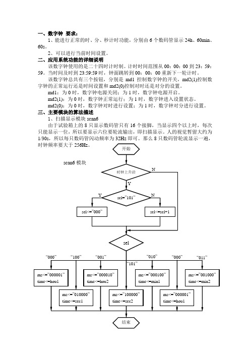
三、主要模块的算法描述1、扫描显示模块scan6由于试验箱上的8只显示数码管只有16个接脚,当显示四个以上时,每次只能显示一位,所以要显示六位要轮流输出,即扫描显示。
人的视觉暂留大约为1/30s,所以每只数码管闪动频率为32Hz即可。
那么8只数码管轮流显示一遍,2、计时模块hourten,huoroen,minten,minone,secten,secone计时模块共分为6个部分,分别是时、分、秒的十位和个位。
由每位之间的逻辑关系以及md1和md2来控制正常计数、进位和对小时分钟的设置。
3、译码模块dec7s把计时模块输出的时、分、秒各位的二进制数翻译成能在七段数码管上显示的七位二进制码,能够显示0~9各个数字。
四、程序的源代码清单library ieee;use ieee.std_logic_1164.all;use ieee.std_logic_unsigned.all;entity digital_clock isport(clk:in std_logic; --扫描频率,>=256Hz clk1:in std_logic; --计时频率,1Hzmd1:in std_logic; --开关,0时有效md2:in std_logic_vector(1 downto 0); --时间设置dout:out std_logic_vector(6 downto 0); --译码显示ms:out std_logic_vector(5 downto 0)); --扫描控制end digital_clock;architecture one of digital_clock issignal sel:std_logic_vector(2 downto 0);signal hou1,hou2,min1,min2,sec1,sec2:std_logic_vector(3 downto 0);signal time:std_logic_vector(3 downto 0);begin---------------------------------------------scan6scan6:process(clk1,hou1,hou2,min1,min2,sec1,sec2)beginif clk1'event and clk1='1' thenif sel="101" thensel<="000";elsesel<=sel+1;end if;end if;case sel iswhen "000"=>ms<="000001";time<=hou1;when "001"=>ms<="000010";time<=hou2;when "010"=>ms<="000100";time<=min1;when "011"=>ms<="001000";time<=min2;when "100"=>ms<="010000";time<=sec1;when "101"=>ms<="100000";time<=sec2;when others=>ms<="100000";time1=sec2;end case;end process scan6;---------------------------------------------hourtenhourten:process(clk,hou2,min1,min2,sec1,sec2,md1,md2)beginif clk'event and clk='1' thenif (hou1&hou2&min1&min2&sec1&sec2="001000110101100101011001") then hou1<="0000"; --当23:59:59时,时十位归0elsif (hou1&hou2="00100011"and md1&md2="001") thenhou1<="0000"; --当设置小时,时位是23时,时十位归0elsif ((hou2&min1&min2&sec1&sec2="10010101100101011001")or(hou2="1001"and md1&md2="001")) thenhou1<=hou1+1; --当正常计时,时间是x9:59:59时,或设置小时,end if; --时位是x9时,时十位加1end if;end process hourten;---------------------------------------------houronehourone:process(clk,min1,min2,sec1,sec2,md1,md2,hou1)beginif clk'event and clk='1' thenif (hou1&hou2&min1&min2&sec1&sec2="001000110101100101011001") then hou2<="0000"; --当23:59:59时,时个位归0elsif (hou2&min1&min2&sec1&sec2="001000110101100101011001") thenhou2<="0000"; --当x9:59:59时,时个位归0elsif ((hou2="1001"or hou1&hou2="00100011")and(md1&md2="001")) thenhou2<="0000"; --当设置小时,时位是x9或23时,时个位归0 elsif (min1&min2&sec1&sec2="0101100101011001)or(md1&md2="001")then hou2<=hou2+1; --当正常计时,时间是xx:59:59时,或设置小时,时个位加1 end if;end if;end process hourone;---------------------------------------------mintenminten:process(clk,min2,sec1,sec2,md1,md2)beginif clk'event and clk='1' thenif (min1&min2&sec1&sec2="0101100101011001") thenmin1<="0000"; --当xx:59:59时,分十位归0elsif (min1&min2="01011001"and md1&md2="000")thenmin1<="0000"; --当设置分钟,分位是59时,分十位归0elsif (min2&sec1&sec2="100101011001")or --正常计时,时间是xx:x9:59时,或(min2="1001"and md1&md2="000") then --设置分钟,时间是x9,分十位加1min1<=min1+1;end if;end if;end process minten;---------------------------------------------minoneminone:process(clk,sec1,sec2,md1,md2)beginif clk'event and clk='1' thenif (min2&sec1&sec2="100101011001") thenmin2<="0000"; --当xx:x9:59时,分个位归0elsif (min2="1001"and md1&md2="000") thenmin2<="0000"; --当设置分钟,分位是x9时分个位归0elsif (sec1&sec2="01011001")or(md1&md2="000") thenmin2<=min2+1; --正常计时,时间是xx:xx:59时,或设置分钟,分个位加1 end if;end if;end process minone;---------------------------------------------sectensecten:process(clk)beginif clk'event and clk='1' thenif (sec1&sec2="01011001") then --当时间是xx:xx:59时,秒十位归0sec1<="0000";elsif sec2="1001"then --当秒位是x9时,秒十位加1sec1<=sec1+1;end if;end if;end process secten;--------------------------------------------seconesecone:process(clk)beginif clk'event and clk='1' thenif sec2="1001" then --当秒位是x9时,秒个位归0sec2<="0000";else sec2<=sec2+1; --否则加1end if;end if;end process secone;------------------------------------------dec7sdec7s:process(time)begincase time iswhen "0000"=>dout<="0111111";when "0001"=>dout<="0000110";when "0010"=>dout<="1011011";when "0011"=>dout<="1001111";when "0100"=>dout<="1100110";when "0101"=>dout<="1101101";when "0110"=>dout<="1111101";when "0111"=>dout<="0000111";when "1000"=>dout<="1111111";when "1001"=>dout<="1101111";when others=>dout<="0111111";end case;end process dec7s;end one;。
电子秒表设计VHDL

一、设计题目:基于VHDL语言的电子秒表设计(可调时,有闹钟、定时功能)二、设计目的:⑴掌握较复杂的逻辑设计和调试⑵学习用原理图+VHDL语言设计逻辑电路⑶学习数字电路模块层次设计⑷掌握QuartusII软件及Modelsim软件的使用方法三、设计内容:(一)设计要求1、具有以二十四小时计时、显示、整点报时、时间设置和闹钟的功能。
2、设计精度要求为1S。
(二).系统功能描述1 . 系统输入:系统状态及校时、定时转换的控制信号为k、set、ds;时钟信号clk,采用实验箱的50MHz;系统复位信号为reset。
输入信号均由按键产生。
系统输出:8位LED七段数码管显示输出,蜂鸣器声音信号输出。
多功能数字钟系统功能的具体描述如下:2. 计时:set=1,ds=1工作状态下,每日按24h计时制计时并显示,蜂鸣器无声,逢整点报时。
3. 校时:在set=0,ds=0状态下,按下“k键”,进入“小时”校准状态,之后按下“k键”则进入“分”校准状态,继续按下“k键”则进入“秒校准”状态,之后如此循环。
1)“小时”校准状态:在“小时”校准状态下,显示“小时”数码管以1Hz的频率递增计数。
2)“分”校准状态:在“分”校准状态下,显示“分”的数码管以1Hz的频率递增计数。
3)“秒”复零状态:在“秒复零”状态下,显示“分”的数码管以1Hz的频率递增计数。
4. 整点报时:蜂鸣器在“59”分钟的第50—59,以1秒为间隔分别发出1000Hz,500Hz的声音。
5. 显示:采用扫描显示方式驱动8个LED数码管显示小时、分、秒。
闹钟:闹钟定时时间到,蜂鸣器发出交替周期为1s的1000Hz、500Hz的声音,持续时间为一分钟;6. 闹钟定时设置:在set=0,ds=1状态下,按下“k”,进入闹钟的“时”设置状态,之后按下“k键”进入闹钟的“分”设置状态,继续按下“k 键”则进入“秒”设置状态, 之后如此循环。
1)闹钟“小时”设置状态:在闹钟“小时”设置状态下,显示“小时”的数码管以1Hz 的频率递增计数。
用VHDL语言编写的数字钟程序
永州职业技术学院课程设计课程名称:EDA技术实用教程题目:基于FPGA的数字钟设计系、专业:电子技术系应用电子年级、班级:07级电子大专学生姓名:**指导老师:***时间:2008年12月目录一、系统设计………………………………………………………..1.1设计要求……………………………………………………1.1.1任务………………………………………………..1.1.2要求……………………………………………….1.1.3题目分析…………………………………………二.方案论证与比较…………………………………2.1方案一…………………………………………2.2 方案二…………………………………………2.3 方案三…………………………………………三、设计思路……………………………………………………3.1硬件模块………………………………………………3.2软件模块………………………………………………….四、调试情况………………………………………………….五、系统调试…………………………………………………六、心得体会……………………………………………………... 附:参考文献……………………………………………………..用VHDL语言编写的数字钟程序摘要:本设计要求一个12进制或24进制的具有时、分、秒计时功能的数字钟,并要求能进行时、分、秒调整,每逢时有报时功能。
数字钟是一种用数字电路技术实现时、分、秒计时的装置,与机械式时钟相比具有更高的准确性和直观性,且无机械装置,具有更更长的使用寿命,因此得到了广泛的使用。
本设计基于FPGA芯片的数字钟的设计,通过多功能数字钟的设计思路,详细叙述了整个系统的硬件、软件实现过程,实现了时间的显示和修改功能、报时功能等,并尽可能的减少误差,使得系统可以达到实际数字钟的允许误差范围内。
关键词:FBGA、数码管、按键一、系统设计1.1 设计要求1.1.1 任务设计并制作一个数字钟,通过设计,掌握电子设计的一般思路,学习电子设计的一般方法。
VHDL语言编写数字钟源代码

library ieee;use ieee.std_logic_1164.all;use ieee.std_logic_arith.all;use ieee.std_logic_unsigned.all;entity clock isport (clk,clr,a,c,e,f,g:in std_logic;led_sel:out std_logic_vector( 2 downto 0);led:out std_logic_vector( 0 to 6);p:in std_logic_vector( 3 downto 0);b:in std_logic_vector(1 downto 0);d:out std_logic );end entity clock;architecture bhv of clock issignal m: integer range 0 to 999;signal hou1,hou0,min1,min0,sec1,sec0,s2:std_logic_vector(3 downto 0);signal rhou1,rhou0,rmin1,rmin0,rsec1,rsec0:std_logic_vector(3 downto 0);signal s1: std_logic_vector(2 downto 0);signal clk1,clk2,d1,d2:std_logic;signal n : integer range 0 to 1;beginp1:process(clk) --二分频beginif (rising_edge(clk)) thenif n=1 then n<=0;clk2<='1';else n<=n+1; clk2<='0';end if;end if ;end process;p2:process(clk)beginif (rising_edge(clk)) thenif m=999 then m<=0;clk1<='1';else m<=m+1; clk1<='0';end if;end if ;end process P2;p3: process(clk1,clr) ---时间设置beginif (clr='1') then sec0<="0000";sec1<="0000";min0<="0000";min1<="0000";hou0<="0000";hou1<="0000";elsif rising_edge(clk1) thenif a='1' then --校时if b="00" then hou1<=p;elsif b="01" then hou0<=p;elsif b="10" then min1<=p;elsif b="11" then min0<=p;end if;end if;if sec0>="1001" thensec0<="0000";if sec1>="0101" thensec1<="0000";if min0>="1001" thenmin0<="0000";if min1>="0101" thenmin1<="0000";if g='0'thenif hou1<"0010" thenif hou0="1001" thenhou0<="0000";hou1<=hou1+1 ;else hou0<=hou0+1;elsif hou1="0010" and hou0="0011" thenhou1<="0000";hou0<="0000";else hou0<=hou0+1;end if ;end if;if g='1'thenif hou1<"0001" thenif hou0="1001" thenhou0<="0000";hou1<=hou1+1 ;else hou0<=hou0+1;end if;elsif hou1="0001" and hou0="0001" thenhou1<="0000";hou0<="0000";else hou0<=hou0+1;end if ;end if;else min1<=min1+1;end if;else min0<=min0+1;else sec1<=sec1+1;end if;else sec0<=sec0+1;end if;end if ;end process P3;p4:process(clk) --数码管选通beginif(rising_edge (clk)) thenif s1="111" thens1<="000";else s1<=s1+1;end if;end if;-- led_sel<=s1;end process;p5:process(s1,f) ---闹铃显示beginif f='0'thencase s1 iswhen "000"=>s2<=sec0;led_sel<="000";when "001"=>s2<=sec1;led_sel<="001";when "010"=>s2<=min0;led_sel<="010";when "011"=>s2<=min1;led_sel<="011";when "100"=>s2<=hou0;led_sel<="100";when "101"=>s2<=hou1;led_sel<="101";when others=>null;end case;elsif f='1' thencase s1 iswhen "010"=>s2<=rmin0;led_sel<="010";when "011"=>s2<=rmin1;led_sel<="011";when "100"=>s2<=rhou0;led_sel<="100";when "101"=>s2<=rhou1;led_sel<="101";when others=>null;end case;end if;end process;p6:process(s2) --七段译码器beginif(s1<6) thencase s2 iswhen "0000"=>led<="0111111"; when "0001"=>led<="0000110"; when "0010"=>led<="1011011"; when "0011"=>led<="1001111"; when "0100"=>led<="1100110"; when "0101"=>led<="1101101"; when "0110"=>led<="1111101"; when "0111"=>led<="0000111"; when "1000"=>led<="1111111"; when "1001"=>led<="1101111"; when others=>null;end case ;else led<="0000000";end if;end process;p7:process(clk1,c) --整点报时beginif (rising_edge(clk))thenif c='1' thenif (min1="0101" and min0="1001" and sec1="0101") then if(sec0="0000"or sec0="0010" or sec0="0100" orsec0="0110" or sec0="1000")thend1<='1'and clk2;else d1<='0';end if;elsif (min1="0000" and min0="0000" and sec0="0000" andsec1="0000") thend1<='1';else d1<='0';end if ;end if ;end if ;end process;p8:process(clk,e) ---闹铃设置beginif (rising_edge(clk))thenif e='1' thenif b="000"then rhou1<=p;elsif b="001"then rhou0<=p;elsif b="010"then rmin1<=p;elsif b="011"then rmin0<=p;end if;end if;end if;end process;p9:process(clk) ---闹铃比较beginif(rising_edge(clk))thenif e='1'thenif(rhou1=hou1 and rhou0=hou0 and rmin1=min1 and rmin0=min0)then if(sec0="0001"or sec0="0010" or sec0="0011" orsec0="0011" or sec0="0100" )thend2<='1'and clk2;else d2<='0';end if;else d2<='0';end if;end if;end if;end process;d<=d1 or d2;end architecture bhv;。
基于VHDL的数字时钟设计

目录1 概述...................................................................... 错误!未定义书签。
1.1数字时钟的工作原理 (1)1.2设计任务 (1)2 系统总体方案设计 (2)3 VHDL模块电路设计 (3)3.1模块实现 (3)3.1.1分频模块pinlv (3)3.1.2按键去抖动模块qudou (5)3.1.3按键控制模块self1 (6)3.1.4秒、分六十进制模块cantsixty (7)3.1.5时计数模块hourtwenty (9)3.1.6秒、分、时组合后的模块 (9)3.1.7数码管显示模块 (10)3.2数字时钟的顶层设计原理图 (13)3.3系统仿真与调试 (14)结束语 (16)参考文献 (17)致谢 (18)附录源程序代码 (19)1 概述1.1数字时钟的工作原理数字钟电路的基本结构由两个60进制计数器和一个24进制计数器组成,分别对秒、分、小时进行计时,当计时到23时59分59秒时,再来一个计数脉冲,则计数器清零,重新开始计时。
秒计数器的计数时钟CLK为1Hz的标准信号,可以由晶振产生的50MHz信号通过分频得到。
当数字钟处于计时状态时,秒计数器的进位输出信号作为分钟计数器的计数信号,分钟计数器的进位输出信号又作为小时计数器的计数信号,每一秒钟发出一个中断给CPU,CPU采用NIOS,它响应中断,并读出小时、分、秒等信息。
CPU对读出的数据译码,使之动态显示在数码管上。
1.2 设计任务设计一个基于VHDL的数字时钟,具体功能要求如下:1.在七段数码管上具有时--分--秒的依次显示。
2.时、分、秒的个位记满十向高位进一,分、秒的十位记满五向高位进一,小时按24进制计数,分、秒按60进制计数。
3.整点报时,当计数到整点时扬声器发出响声。
4.时间设置:可以通过按键手动调节秒和分的数值。
此功能中可通过按键实现整体清零和暂停的功能。
- 1、下载文档前请自行甄别文档内容的完整性,平台不提供额外的编辑、内容补充、找答案等附加服务。
- 2、"仅部分预览"的文档,不可在线预览部分如存在完整性等问题,可反馈申请退款(可完整预览的文档不适用该条件!)。
- 3、如文档侵犯您的权益,请联系客服反馈,我们会尽快为您处理(人工客服工作时间:9:00-18:30)。
三、实验程序及部分仿真波形图
library ieee;
use ieee.std_logic_1164.all;
use ieee.std_logic_unsigned.all;
entity colock is
port(clk1,clk2,key1,key2: in std_logic;
abc:out std_logic_vector(2 downto 0);
led7s:out std_logic_vector(6 downto 0) );
end entity;
architecture one of colock is
signal ctrl:std_logic_vector(3 downto 0);
signal clk02,cs02,cm02,cs1,cs2,cm1,cm2,ch1,cp,k2,ck1,ck2:std_logic;
signal s1,s2,m1,m2,h1,h2,s01,s02,m01,m02,h01,h02,s001,s002,m001,m002,h001, h002,p1,p2,disp:std_logic_vector(3 downto 0);
signal ctrl0:std_logic_vector(8 downto 0);
signal tmp1,tmp2:std_logic_vector(9 downto 0);
signal k1:std_logic_vector(1 downto 0);
begin
--当处于按键调时状态时,根据K1的值来确定所调整的位,被调整的位送按键2产生的脉冲(CK2),其余进位脉冲赋0屏蔽掉
process(k1,clk2,clk02,cs2,cm2,ck2)
begin
case k1 is
when "00" => clk02<=clk2;cs02<=cs2;cm02<=cm2;
when "01" => clk02<=ck2;cs02<='0';cm02<='0';
when "10" => clk02<='0';cs02<=ck2;cm02<='0';
when "11" => clk02<='0';cs02<='0';cm02<=ck2;
when others => clk02<=clk2;cs02<=cs2;cm02<=cm2;
end case ;
end process;
--500进制计数器,每500ms对CP进行取反一次,用于闪烁控制
process(clk1)
begin
if rising_edge(clk1) then
if ctrl0<499 then ctrl0<=ctrl0+1;
else ctrl0<="000000000";cp<=not cp;
end if;
end process;
--数码管动态扫描,接138的输入端
process(clk1)
begin
if rising_edge(clk1) then
if ctrl<9 then ctrl<=ctrl+1;
else ctrl<="0000";
end if ;
end if ;
end process;
abc<=ctrl(2 downto 0);
--秒个位的计数
process(clk02)
begin
if rising_edge(clk02) then
if s01<"1001" then s01<=s01+1;cs1<='0';
else s01<="0000";cs1<='1';
end if;
end if;
end process;
--秒十位的计数
process(cs1)
begin
if rising_edge(cs1) then
if s02<"0101" then s02<=s02+1;cs2<='0';
else s02<="0000";cs2<='1';
end if;
end if;
end process;
--分个位的计数
process(cs02)
begin
if rising_edge(cs02) then
if m01<"1001" then m01<=m01+1;cm1<='0';
else m01<="0000";cm1<='1';
end if;
end if;
--分十位的计数
process(cm1)
begin
if rising_edge(cm1) then
if m02<"0101" then m02<=m02+1;cm2<='0';
else m02<="0000";cm2<='1';
end if;
end if;
end process;
--小时个位的计数
process(cm02)
begin
if rising_edge(cm02) then
if h02<"0010" then
if h01<"1001" then h01<=h01+1;ch1<='0';
else h01<="0000";ch1<='1';
end if ;
else
if h01<"0011"then h01<=h01+1;ch1<='0';
else h01<="0000";ch1<='1';
end if;
end if;
end if;
end process;
--小时十位的计数
process(ch1)
begin
if rising_edge(ch1) then
if h02<"0010" then h02<=h2+1;
else h02<="0000";
end if;
end if;
end process;
--按键一去抖动
process(clk1)
begin
if rising_edge(clk1) then
tmp1(0)<=key1;tmp1(9 downto 1)<=tmp1(8 downto 0);
1.第五章心得体会
通过此次课程设计使我更加深刻的认识EDA电子电路设计的各个模块。
时钟程序的编写按键调整时间同时让处于调整的位闪烁体会到各个进程之间通过控制信号建立起来的紧密联系,以及通过移位来达到按键的去抖动。
进行硬件调试时了解到芯片跟外围设备之间的连接程序功能由简单到复杂,通过课堂提问一步步完善时钟的各个模块,将本学期所学到的内容串到一起,最终完成课程设计。