ACER as1400sg笔记本电脑使用维修+拆解[原厂手册]
acer笔记本电脑屏幕坏了怎么办
acer笔记本电脑屏幕坏了怎么办总在网上看到很多本本的液晶屏坏掉的故事,那么大家知道acer 笔记本电脑屏幕坏了怎么办吗?接下来大家跟着店铺一起来了解一下acer笔记本电脑屏幕坏了的解决方法吧。
acer笔记本电脑屏幕坏了解决方法我们说笔记本屏幕坏了,就要更换,去维修点更换一块屏幕的价格有些用户接受不了,所以常常会有人采用自己更换屏幕的方法来解决这个问题,接下来就跟着笔者一起来看看如何自己动手更换屏幕把。
步骤一:拆卸屏幕外壳我们首先要准备十字螺丝刀和镊子两种工具。
屏幕螺丝都集中在屏幕正面的缓冲垫下面,用镊子小心抠下缓冲垫,就可以见到固定螺丝,一一卸下后,屏幕的外框就可以剥离了。
步骤二:拆卸屏幕屏幕外壳螺丝以及屏幕螺丝被拧下后,我们开始小心的拔下排线,因为摄像头线笔记本小,所以这里要用镊子来帮忙;而屏幕排线往往都是比较还拆的,把两个先顺利拆开后,我们的屏幕就与A面彻底分离了。
步骤三:安装新屏幕其实这个步骤就是重复之前的两个步骤罢了,只是在安装排线时一定要认真仔细,不然安装上的屏幕会点不亮哦。
笔记本使用时间长了屏幕就会老化,出现图像不清,色泽不均等现象。
这是显示屏发光管老化导致的结果,标志着液晶显示屏已经老化。
下面笔者为大家介绍减缓笔记本电脑屏幕变黄,老化的几个小方法:尽量降低屏幕亮度:在笔记本电脑工作时,可以将屏幕亮度设置为2~3格亮度,即可以延长屏幕寿命,又可以保护视力;在临时不使用笔记本电脑时可以将屏幕关闭。
保持屏幕清洁:过多污渍不但影响视觉,同时也影响屏幕寿命。
可以使用专用擦布清洁屏幕,如果屏幕上有顽固污渍可以使用专用屏幕清洁剂进行清理。
记住,不管使用什么方法清理,都需要将笔记本电脑停止工作后进行。
避免日光暴晒:阳光直接暴晒是屏幕老化的主要杀手,暴晒提高了屏幕工作温度,使屏幕发光管迅速老化,所以我们应该尽量避免在强光下使用笔记本电脑。
避免坚硬固体接触屏幕:手指、笔尖等坚硬物体也是液晶屏幕的主要杀手,经常使用坚硬物体接触屏幕,容易导致屏幕出现坏点,大大缩短了液晶屏幕寿命。
笔记本电脑维修手册(清晰版)
笔记本电脑维修指导手册
前言
本手册的编写宗旨是:规范维修工程师在进行电脑产品维修过程中的行为, 并为判断及定位故障提供通用的一般方法。我们非常希望这本手册能为广大维修 工程师的维修工作提供帮助,并成为广大工程师的伙伴。
IT技术及网络的发展,使得维修过程日益复杂。维修经验是一个不断积累 的过程,编写这本手册也就是试图将电脑运行过程中所遇到的各种故障加以归 纳,并将优秀工程师的处理经验加以总结和提炼,使之形成联想维修工程师的共 同财富。我们希望,对于刚刚接触维修工作不久的你,或有一定维修经验但希望 进行总结提高的你,这本手册都可以对你在理清解决故障的思路和方法方面有所 帮助。
二、拆卸时需要的注意事项 1、首先拆卸笔记本时需要绝对细心,对准备拆装的部件一定要仔细观察,明确拆
卸顺序、安装部位,必要时用笔记下步骤和要点。 2、当使用合适的工具,如镊子,钩针等工具。但使用时也要小心,不要对电脑造
成人为损伤。 3、拆卸各类电缆(电线)时,不要直接拉拽,而要明确其端口是如何吻合的,然
笔记本电脑维修指导手册
求及电源 DC 板是否正常。 1。7、先通病,后特殊
根据笔记本电脑故障的共同特点及各个机器型号特有的故障现象,先排除带 有普遍性和规律性的常见故障,然后再去检查特殊的故障,以便逐步缩小故障范 围,由面到点,缩短修理时间。 1。8、先外围,后内部
由于笔记本电脑本身在拆装方面的特殊性,可能不同的机型在拆装同一部件 的难度差别非常大,因此,我们在维修的时候要灵活运用,不能一味墨守成规, 在检测的时候要从简单易查的部件开始,本着解决问题的思路,灵活运用,更好 的为客户服务。,
笔记本电脑维修指导手册
二零零三年一月
笔记本电脑维修指导手册
宏基上网本拆机图解
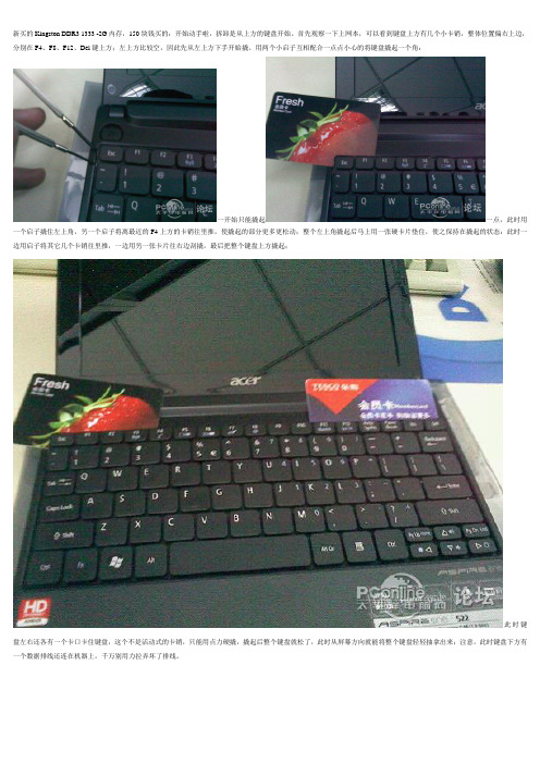
新买的Kingston DDR3 1333 -2G内存,150块钱买的:开始动手啦,拆卸是从上方的键盘开始。
首先观察一下上网本,可以看到键盘上方有几个小卡销,整体位置偏右上边,分别在F4、F8、F12、Del键上方;左上方比较空,因此先从左上方下手开始撬。
用两个小启子互相配合一点点小心的将键盘撬起一个角:一开始只能撬起一点,此时用一个启子撬住左上角,另一个启子将离最近的F4上方的卡销往里推,使撬起的部分更多更松动;整个左上角撬起后马上用一张硬卡片垫住,使之保持在撬起的状态:此时一边用启子将其它几个卡销往里推,一边用另一张卡片往右边刮撬,最后把整个键盘上方撬起;此时键盘左右还各有一个卡口卡住键盘,这个不是活动式的卡销,只能用点力硬撬,撬起后整个键盘就松了,此时从屏幕方向就能将整个键盘轻轻抽拿出来;注意,此时键盘下方有一个数据排线还连在机器上,千万别用力拉弄坏了排线。
这是键盘底下连着机器的排线:下一步是拆下排线(如果怕麻烦可以不拆这个排线,不过后面的步骤就需要时时非常小心以避免损坏排线)。
注意图片中卡住排线的那个插座,上方黑色部分是焊在机器的电路板上的,下面白色部分是连在上面的卡子,可活动的,往上推到顶可以把排线紧紧压在插座上,这是安装好的状态;用启子轻轻的将卡子左右的两个卡脚往下拨(见红箭头),这样白色的卡子就推下来了,排线就松了,轻轻的就拔了出来。
拔去排线后的插座,注意,白色的卡子已经推到了下方。
拆去键盘后的下面景象。
接下来用十字螺丝刀拆下四个标注“1”的螺丝;然后用螺丝刀对准标注为“2”的孔伸进去朝下推,稍微用点力,可以把上网本的底部整体盖板推下来;注意要先把整个上网本抱住左右两侧端起来,不要压住底盖,否则推不动的。
侧面看去,看到没,底盖一个角已经被推开了,顺势把整个底盖掰下来吧。
拆开底盖后的AspireOne522,内存条、硬盘一目了然;呵呵,此时想干啥就干啥吧。
换好内存后,机器拆下来的东西原样装回去就是,不再多叙述了;装键盘排线的时候要小心点,装好后别急着扣紧键盘,可先试试看好不好。
宏碁笔记本拆机教程

宏碁笔记本拆机教程
如果您想了解如何拆解宏碁笔记本,我们将为您提供一个简单的教程。
拆解笔记本可能会对硬件造成损坏,因此,请您在拆解之前确保备份所有重要数据,并在确保了解自己的操作能力后进行操作。
在拆解之前,您需要准备一些必要的工具,如螺丝刀、塑料刮板和细小的夹子。
第一步是关闭电脑并断开电源连接。
确保您已经关闭了电源并拔掉电源适配器。
同时,还需要将电池拆卸掉,以避免电流对您造成伤害。
第二步是使用细小的螺丝刀在笔记本的底部找到所有的螺丝。
这些螺丝通常带有一个小图标,用以表示该螺丝应该拧松。
使用螺丝刀拧松它们并将它们放在一个安全的地方,以防丢失。
第三步是使用塑料刮板或相似的工具来慢慢弯曲和拆卸笔记本的外壳。
通常情况下,外壳被固定在一起,需要小心地将其揭开。
利用塑料刮板贴近外壳,然后轻轻地用力将其撬开。
需要注意的是,在撬开过程中要避免使用过大的力量,以免导致外壳、电路板或其他硬件的损坏。
第四步是拆卸内部硬件。
首先,在拆卸之前要先熟悉笔记本的内部结构和硬件组件的位置。
通常来说,硬盘、内存、无线网卡和风扇都是常见的内部硬件组件。
运用夹子轻轻地拆下这些硬件,确保不要损坏金属接头或电缆。
最后,将拆解的过程倒过来,重新组装笔记本。
确保将每个硬
件部件正确地插入到相应的插槽或接口中,然后将外壳盖好并用螺丝刀拧紧螺丝。
总结:拆解宏碁笔记本需要小心和耐心,确保在拆卸和组装过程中不损坏硬件。
如果您对自己的操作能力不确定,强烈建议联系专业技术人员来进行拆解和维修。
宏基Acer笔记本电脑拆机图文详解

宏基Acer笔记本电脑拆机图文详解
推荐文章
笔记本电脑启用媒体流功能的方法详解热度:笔记本电脑一体机无法安装扫描仪的处理方法详解热度:笔记本电脑更改Win10升级预定步骤详解热度:笔记本电脑开机密码忘记的解决方法热度:电脑删除虚拟wifi方法步骤热度:
有很多小伙伴还不知道宏基Acer笔记本电脑如何拆解,所以想清理笔记本都无计可施了,不过没关系,下面就由店铺跟大家分享宏基Acer笔记本电脑拆机图文详解吧,欢迎大家来阅读学习。
宏基Acer笔记本电脑拆机图文详解
首先先翻过来背面,拆掉螺丝,取下电池。
揭开背面的盖子之后,拆掉内存条。
取掉螺丝,硬盘取得时候用力往左推。
取网卡的时候按住网卡的两个点就很容易的取下来了。
把背面的螺丝都卸下。
再把电脑翻过来,准备取键盘。
取得时候注意后面的排线。
一定要轻一些,用力过大容易导致连接的地方坏掉。
抠排线的时候,先把两头黑色的部分退出去,然后再取排线。
取出风扇的部分,卸下风扇就可以清理了。
按照步骤把电脑装回去,做开机测试。
戴尔DELL14201400详细拆机清理风扇以及主板拆解
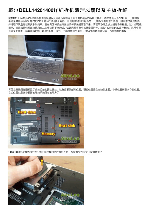
戴尔DELL14201400详细拆机清理风扇以及主板拆解戴尔DELL 1420|1400详细拆机清理风扇以及主板拆解等⽹上关于戴尔机器的拆解⽐较少,不知道是因为DELL设计上⽐较简单还是其他原因呢?感觉吧DELL的10个机器9个好拆,但是也有遇到不好拆的,⽐如今天看到这个机器,如果你仅仅是想拆开清理下风扇的话其实⾮常简单,就在背⾯将后盖打开然后将散热铜管取下来,清理⼲净并且换上新的导热硅脂,这个都是很简单,但是如果你想继续将风扇从主板上拆下来的话,估计需要将整个机器全部拆开,就如1400 和1420是⼀样的,这两个型号只是配置不⼀样戴尔1420与1400拆机是⼀样的。
下⾯是我们⼿⾥的⼀台1400的戴尔笔记本,作为拆机的教程:背⾯我已经⽤红圈标注了这些后盖的固定螺丝,以及组要的部件位置,硬盘位置是在左边的上⾯,中间位置则是内存的位置,右边位置就是这台机器的散热系统所在的地⽅了1400 1420的硬盘拆机更换:如下图中我们将后盖打开后,按照箭头⽅向拉出硬盘就有了硬盘上⾯还套了⼀个转接⼝,个⼈觉得这个东西完全没必要,浪费时间还增加机器的损坏率中间的那个后盖下⾯就是内存了,原⼚出来的话应该会预留⼀个内存槽位置⽤来以后升级,下图中是我们已经升级了内存的,将两边固定内存的⾦属⽚拨开,然后抽出内存就可以了DELL1420 1400光驱的拆卸:下图中红圈位置就是固定这台DELL 笔记本光驱的螺丝,拧开后拔出光驱就可以了很简单的。
散热⽚拆卸:下图中就是笔记本最右边的位置了,后盖下⾯就是处理器的散热⽚了,拧开固定在处理器上的螺丝,拿出来就可以了,明显好多灰尘啊,⼀般来说⼀台笔记本电脑需要在1年半左右的时间清理⼀次,如果⽐较⼲净的地⽅那么2年也得要清理的乐。
散热⽚上⾯有固定的螺丝,⼀共四个如果你想继续拆的话,⽐如键盘的拆卸,那么就需要到前⾯来了,如下图中将键盘前⾯的挡板拆开,⼀般来说DELL都喜欢将这个挡板设计成没有螺丝固定的,所以在右边翘起来就可以了还是和以前的设计⼀样,DELL总是喜欢这样的设计,然后你就能看到隐藏在挡板下⾯的键盘固定螺丝了,下图中我们将螺丝都拧开键盘最下⾯还有排线位置了,排线怎么办呢?我们也来了特写,⽅⾯菜鸟们⾃⼰来拆机DELL 1400拆机和DELL 1420拆机⼀样,下图中的键盘排线有个卡⼝固定,将卡⼝打开就能顺利将排线抽出去我们已经标注的⽐较明显了键盘就被顺利的从主机中取出来了,银⾊的键盘使⽤时间长了就⽐较难看,因为会掉漆。
笔记本屏幕拆机教程-acer

工欲善其事必先利其器。
螺丝刀绝对是电脑玩家必备,相信各位手中也不会少。
刀头各种各样,其实很多很少用到,但是万一需要的时候又真是没有不行。
比如任天堂专用的Y字形等等。
对于拆笔记本来说,其实必备的也就是几种尺寸的十字和一个一字(主要做撬棍用,选薄的,在保证强度前提下越薄越方便。
我用的专门的弯头)镊子在对付某些细小部件时候有很好的效果,但不是必须导热硅脂,用于CPU和散热器之间的导热。
如果不拆开CPU散热器则不需要。
我用的是北极银5,12克装。
Amazon价格20美金。
另外除了所有的工具之外,还需要一个至少一平方米的操作空间,因为会有很多零件需要摆放,千万不要乱丢,否则你会后悔的。
===============================正式开工,我这里就以我自己的ACER 4736z为例子进行。
首先拔出所有的连接线缆并退出读卡器内的卡片。
然后将笔记本翻到D面。
拆除电池。
在地毯房里操作,容易有静电,安全考虑最好先去洗个手,水流会带走电荷。
冬天尤其必要。
卸掉所有可以拆卸的盖板。
部分厂商可能会在这些上面贴上易碎贴,作为保修凭证。
如果不想失去保修的话,电吹风伺候吧。
手上一定要小心。
我自己是懒得做的,无所谓。
自觉RP还可以,从来不保修。
一般情况下,所有盖板的螺丝都是固定在盖板上的,避免丢失。
如果没有固定的,需要妥善保管。
最好和盖板放在一起。
无线网卡上,一般会连接有天线,有条件记得拍照记下接线位置,避免接错。
内存部分都是有下图圈中这样的卡扣卡住。
按照箭头方向推开卡扣就行了。
推开之后内存会自动弹起,顺势拔出即可。
硬盘部分则不尽相同,有各种的锁定方式,有的还需要再拆卸螺丝,不过大多提供塑料弹片便于拖拽。
按照指引拆卸吧。
对于我的笔记本,往箭头方向拖拽,使框中金手指部分脱离即可。
无线网卡,内存,硬盘拆下后妥善放置。
回来看拆下部件之后的D面,下一步的工作是拆除该面所有螺丝。
找来一张白纸,对应D面螺丝孔位,在纸上相应位置画下小圈,不需要十分精确。
宏基电脑拆机_更换内存
宏基Aspire One上网本更换内存拆机教程
宏基Aspire One上网本更换内存拆机教程工具/原料十字螺丝刀硬塑料卡片步骤/方法
一、
首先笔记本电脑拆机还是要先拿下电池的,再用比较硬一点的塑料卡片来撬键盘,比如银行卡这种的。
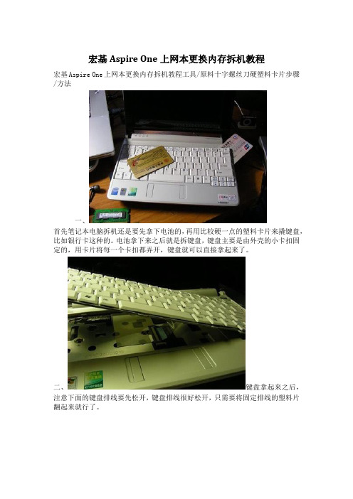
电池拿下来之后就是拆键盘,键盘主要是由外壳的小卡扣固定的,用卡片将每一个卡扣都弄开,键盘就可以直接拿起来了。
二、键盘拿起来之后,注意下面的键盘排线要先松开,键盘排线很好松开,只需要将固定排线的塑料片翻起来就行了。
三、拆掉笔记本背面的所有螺丝,图中的螺钉都比较小,螺丝刀一定要选很小的那种,否则很容易弄花螺丝口。
四、底部的螺丝都拧掉之后,再将键盘下面C壳的螺丝也全部拧掉,抽出触摸板排线,直接将C壳撬起来。
五、C壳拿掉之后,就能够看见主板了,很明显能够看到主板上面的集成内存颗粒。
主板要拿下来,首先就是要清理掉主板上面所有的螺丝已经各种排线。
六、下方的无线网卡模块,网卡信号线有两根直接撤下来就行了。
然后拧掉上面的螺丝就能够将无线网卡模块拿下来了。
七、主板上面的螺丝一旦有这种白色的三角形标记,就是代表这可螺丝是需要取下来的。
八、
主板上面的螺丝已经各种插线去不取下来之后,主板就可以拿下来了,这里就能够看见内存的插槽了,更换内存或者添加内存都可以进行了,或者给笔记本的风扇清灰也是可以顺便的。
- 1、下载文档前请自行甄别文档内容的完整性,平台不提供额外的编辑、内容补充、找答案等附加服务。
- 2、"仅部分预览"的文档,不可在线预览部分如存在完整性等问题,可反馈申请退款(可完整预览的文档不适用该条件!)。
- 3、如文档侵犯您的权益,请联系客服反馈,我们会尽快为您处理(人工客服工作时间:9:00-18:30)。
Acer Aspire 1400 SeriesService GuidePART NO.: VD.A02V5.001PRINTED IN TAIWAN Service guide files and updates are availableon the ACER/CSD web; for more information,please refer toRevision HistoryPlease refer to the table below for the updates made on Aspire 1400 service guide.Date Chapter Updates IVCopyrightCopyright © 1999 by Acer Incorporated. All rights reserved. No part of this publication may be reproduced, transmitted, transcribed, stored in a retrieval system, or translated into any language or computer language, in any form or by any means, electronic, mechanical, magnetic, optical, chemical, manual or otherwise, without the prior written permission of Acer Incorporated.DisclaimerThe information in this guide is subject to change without notice.Acer Incorporated makes no representations or warranties, either expressed or implied, with respect to the contents hereof and specifically disclaims any warranties of merchantability or fitness for any particular purpose. Any Acer Incorporated software described in this manual is sold or licensed "as is". Should the programs prove defective following their purchase, the buyer (and not Acer Incorporated, its distributor, or its dealer) assumes the entire cost of all necessary servicing, repair, and any incidental or consequentialdamages resulting from any defect in the software.Acer is a registered trademark of Acer Corporation.Intel is a registered trademark of Intel Corporation.Pentium and Pentium II/III are trademarks of Intel Corporation.Other brand and product names are trademarks and/or registered trademarks of their respective holders.VConventionsThe following conventions are used in this manual:SCREEN MESSAGES Denotes actual messages that appearon screen.NOTE Gives bits and pieces of additionalinformation related to the currenttopic.WARNING Alerts you to any damage that mightresult from doing or not doing specificactions.CAUTION Gives precautionary measures toavoid possible hardware or softwareproblems.IMPORTANT Reminds you to do specific actionsrelevant to the accomplishment ofprocedures.VIPrefaceBefore using this information and the product it supports, please read the following general information.1.This Service Guide provides you with all technical information relating to the BASIC CONFIGURATIONdecided for Acer's "global" product offering. To better fit local market requirements and enhance product competitiveness, your regional office MAY have decided to extend the functionality of a machine (e.g.add-on card, modem, or extra memory capability). These LOCALIZED FEATURES will NOT be covered in this generic service guide. In such cases, please contact your regional offices or the responsiblepersonnel/channel to provide you with further technical details.2.Please note WHEN ORDERING FRU PARTS, that you should check the most up-to-date informationavailable on your regional web or channel. If, for whatever reason, a part number change is made, it will not be noted in the printed Service Guide. For ACER-AUTHORIZED SERVICE PROVIDERS, your Acer office may have a DIFFERENT part number code to those given in the FRU list of this printed ServiceGuide. You MUST use the list provided by your regional Acer office to order FRU parts for repair andservice of customer machines.VIIVIIITable of Contents Chapter 1 System Specifications 3 Features . . . . . . . . . . . . . . . . . . . . . . . . . . . . . . . . . . . . . . . . . . . . . . . . . . . . . . . . . . 3System Block Diagram . . . . . . . . . . . . . . . . . . . . . . . . . . . . . . . . . . . . . . . . . . . . . . . 5Board Layout . . . . . . . . . . . . . . . . . . . . . . . . . . . . . . . . . . . . . . . . . . . . . . . . . . . . . . 6 Top View . . . . . . . . . . . . . . . . . . . . . . . . . . . . . . . . . . . . . . . . . . . . . . . . . . . . . . 6Bottom View . . . . . . . . . . . . . . . . . . . . . . . . . . . . . . . . . . . . . . . . . . . . . . . . . . . 7 Outlook View . . . . . . . . . . . . . . . . . . . . . . . . . . . . . . . . . . . . . . . . . . . . . . . . . . . . . . . 9 Front View . . . . . . . . . . . . . . . . . . . . . . . . . . . . . . . . . . . . . . . . . . . . . . . . . . . . . 9Left Panel . . . . . . . . . . . . . . . . . . . . . . . . . . . . . . . . . . . . . . . . . . . . . . . . . . . . 11Right Panel . . . . . . . . . . . . . . . . . . . . . . . . . . . . . . . . . . . . . . . . . . . . . . . . . . . 12Rear Panel . . . . . . . . . . . . . . . . . . . . . . . . . . . . . . . . . . . . . . . . . . . . . . . . . . . 13Bottom Panel . . . . . . . . . . . . . . . . . . . . . . . . . . . . . . . . . . . . . . . . . . . . . . . . . 14 Indicators . . . . . . . . . . . . . . . . . . . . . . . . . . . . . . . . . . . . . . . . . . . . . . . . . . . . . . . . 15Keyboard . . . . . . . . . . . . . . . . . . . . . . . . . . . . . . . . . . . . . . . . . . . . . . . . . . . . . . . . 17 Lock Keys . . . . . . . . . . . . . . . . . . . . . . . . . . . . . . . . . . . . . . . . . . . . . . . . . . . . 17 Embedded Numeric Keypad . . . . . . . . . . . . . . . . . . . . . . . . . . . . . . . . . . . . . . . . . . 18Windows Keys . . . . . . . . . . . . . . . . . . . . . . . . . . . . . . . . . . . . . . . . . . . . . . . . . . . . 19Hot Keys . . . . . . . . . . . . . . . . . . . . . . . . . . . . . . . . . . . . . . . . . . . . . . . . . . . . . . . . . 20Keyboard Ergonomics . . . . . . . . . . . . . . . . . . . . . . . . . . . . . . . . . . . . . . . . . . . . . . 21Touchpad . . . . . . . . . . . . . . . . . . . . . . . . . . . . . . . . . . . . . . . . . . . . . . . . . . . . . . . . 22 Touchpad Basics . . . . . . . . . . . . . . . . . . . . . . . . . . . . . . . . . . . . . . . . . . . . . . 22 Launch Keys . . . . . . . . . . . . . . . . . . . . . . . . . . . . . . . . . . . . . . . . . . . . . . . . . . . . . . 24Hardware Specifications and Configurations . . . . . . . . . . . . . . . . . . . . . . . . . . . . . 25 Chapter 2 System Utilities 37 BIOS Setup Utility . . . . . . . . . . . . . . . . . . . . . . . . . . . . . . . . . . . . . . . . . . . . . . . . . . 37 Navigating the BIOS Utility . . . . . . . . . . . . . . . . . . . . . . . . . . . . . . . . . . . . . . . 37Main . . . . . . . . . . . . . . . . . . . . . . . . . . . . . . . . . . . . . . . . . . . . . . . . . . . . . . . . 38Advanced . . . . . . . . . . . . . . . . . . . . . . . . . . . . . . . . . . . . . . . . . . . . . . . . . . . . 40Security . . . . . . . . . . . . . . . . . . . . . . . . . . . . . . . . . . . . . . . . . . . . . . . . . . . . . . 42Others . . . . . . . . . . . . . . . . . . . . . . . . . . . . . . . . . . . . . . . . . . . . . . . . . . . . . . . 45Boot . . . . . . . . . . . . . . . . . . . . . . . . . . . . . . . . . . . . . . . . . . . . . . . . . . . . . . . . . 46Exit . . . . . . . . . . . . . . . . . . . . . . . . . . . . . . . . . . . . . . . . . . . . . . . . . . . . . . . . . 47 BIOS Phlash Utility . . . . . . . . . . . . . . . . . . . . . . . . . . . . . . . . . . . . . . . . . . . . . . . . . 48System Diagnostic Diskette . . . . . . . . . . . . . . . . . . . . . . . . . . . . . . . . . . . . . . . . . . 48 Running Diagnostic Program . . . . . . . . . . . . . . . . . . . . . . . . . . . . . . . . . . . . . 49 Chapter 3 Machine Disassembly and Replacement 55 General Information . . . . . . . . . . . . . . . . . . . . . . . . . . . . . . . . . . . . . . . . . . . . . . . . 56 Before You Begin . . . . . . . . . . . . . . . . . . . . . . . . . . . . . . . . . . . . . . . . . . . . . . 56 Disassembly Procedure Flowchart . . . . . . . . . . . . . . . . . . . . . . . . . . . . . . . . . . . . . 57Removing the HDD Module/FDD Module/RAM Door and Optical Drive . . . . . . . . 60Removing the LCD Module/the Power Board and the Keyboard . . . . . . . . . . . . . . 61 Removing the LCD Module . . . . . . . . . . . . . . . . . . . . . . . . . . . . . . . . . . . . . . . 61Removing the Power Board and the Keyboard . . . . . . . . . . . . . . . . . . . . . . . . 61 Disassembling the Main Unit . . . . . . . . . . . . . . . . . . . . . . . . . . . . . . . . . . . . . . . . . 62 Separate the main unit into the logic upper and the logic lower assembly . . . 62Disassembling the logic upper . . . . . . . . . . . . . . . . . . . . . . . . . . . . . . . . . . . . 62Disassembling the logic lower . . . . . . . . . . . . . . . . . . . . . . . . . . . . . . . . . . . . . 64 Disassembling the LCD Module . . . . . . . . . . . . . . . . . . . . . . . . . . . . . . . . . . . . . . . 66Disassembling the External Modules . . . . . . . . . . . . . . . . . . . . . . . . . . . . . . . . . . . 67 Disassembling the HDD Module 67Disassembling the Floppy Disk Drive Module . . . . . . . . . . . . . . . . . . . . . . . . . 67Disassembling the Optical Drive Module . . . . . . . . . . . . . . . . . . . . . . . . . . . . 67ITable of ContentsChapter 4 Troubleshooting 69 System Check Procedures . . . . . . . . . . . . . . . . . . . . . . . . . . . . . . . . . . . . . . . . . . . 70 External Diskette Drive Check . . . . . . . . . . . . . . . . . . . . . . . . . . . . . . . . . . . . 70External CD-ROM Drive Check . . . . . . . . . . . . . . . . . . . . . . . . . . . . . . . . . . . 70Keyboard or Auxiliary Input Device Check . . . . . . . . . . . . . . . . . . . . . . . . . . . 71Memory Check . . . . . . . . . . . . . . . . . . . . . . . . . . . . . . . . . . . . . . . . . . . . . . . . 71Power System Check . . . . . . . . . . . . . . . . . . . . . . . . . . . . . . . . . . . . . . . . . . . 71Touchpad Check . . . . . . . . . . . . . . . . . . . . . . . . . . . . . . . . . . . . . . . . . . . . . . . 72 Power-On Self-Test (POST) Error Message . . . . . . . . . . . . . . . . . . . . . . . . . . . . . 73Index of Error Messages . . . . . . . . . . . . . . . . . . . . . . . . . . . . . . . . . . . . . . . . . . . . . 74Index of Symptom-to-FRU Error Message . . . . . . . . . . . . . . . . . . . . . . . . . . . . . . . 77Intermittent Problems . . . . . . . . . . . . . . . . . . . . . . . . . . . . . . . . . . . . . . . . . . . . . . . 80Undetermined Problems . . . . . . . . . . . . . . . . . . . . . . . . . . . . . . . . . . . . . . . . . . . . . 81Index of AFlash BIOS Error Message . . . . . . . . . . . . . . . . . . . . . . . . . . . . . . . . . . . 82Top View . . . . . . . . . . . . . . . . . . . . . . . . . . . . . . . . . . . . . . . . . . . . . . . . . . . . . . . . . 83 Chpater 5 Jumper and Connector Locations 83 SW1 Settings (Lid switch) . . . . . . . . . . . . . . . . . . . . . . . . . . . . . . . . . . . . . . . . 84SW2 Settings . . . . . . . . . . . . . . . . . . . . . . . . . . . . . . . . . . . . . . . . . . . . . . . . . 84 Bottom View . . . . . . . . . . . . . . . . . . . . . . . . . . . . . . . . . . . . . . . . . . . . . . . . . . . . . . 85 Chapter 6 FRU (Field Replaceable Unit) List 87 Aspire 1400 . . . . . . . . . . . . . . . . . . . . . . . . . . . . . . . . . . . . . . . . . . . . . . . . . . . . . . 104 Appendix A Model Definition and Configuration 105 Main Features . . . . . . . . . . . . . . . . . . . . . . . . . . . . . . . . . . . . . . . . . . . . . . . . . . . . 105 Appendix B Test Compatible Components 107 Microsoft Windows XP Environment Test . . . . . . . . . . . . . . . . . . . . . . . . . . . . . . . 108 Appendix C Online Support Information 109 Index 111IIChapter 13FeaturesThis computer was designed with the user in mind. Here are just a few of its many features:Performance!Intel ® Pentium TM IV processor with on-die level 2 cache !256 MB memory expandable to 1G !High-capacity, Enhanced-IDE hard disk !Lithium-Ion battery pack !Power management systemDisplayThe large graphics display offers excellent viewing, display quality and desktop-performance graphics.!Thin-Film Transistor (TFT) liquid-crystal display (LCD) displaying 16.7 million colors at 1024X768 eXtended Graphics Array (XGA) resolution!Video performance is boosted with 16 MB of Double Data Rate (DDR) Synchronous Dynamic Random Access Memory (SDRAM) for graphics-intensive games and applications.Multimedia!16-bit high-fidelity stereo audio with 3-D sound !Built-in dual stereo speakers !Internal optical drive (CD-ROM, DVD-ROM, or DVD/CD-RW combo)!Audio DJ feature !Large LCD display with simultaneous LCD and CRT display support !S-video (NTSC/PAL) outputConnectivity!High-speed 56Kbps V.90 fax/data software modem !Ethernet/Fast Ethernet (10/100 Mbps)!Universal Serial Bus (USB) ports !S-video (NTSC/PAL) outputSystem SpecificationsChapter 1Human-centric design and ergonomics!All-in-one design (CD or DVD, floppy drive, and hard disk)!Sleek, smooth and stylish design!Full-sized keyboard!Wide and curved palm rest!Ergonomically-centered touchpad pointing device!Launch keys (supports Audio DJ feature)!Wireless networking (802.11b) optionExpansion!Upgradeable memory and hard disk!CardBus PC Card slotsKeyboard and Pointing Device!87 keys with 101/102 key emulation! 1 Windows Key, 1 Application Key!Ergonomically-centered touchpad pointing deviceI/O Ports!One 25 pins parallel port, EPP/ECP capability!One 15 pins CRT port, Support DDC 2B!One TV-out connector!One MIC In port!One headphone-out!One DC-in jack!One type III or two type II PCMCIA Card Bus slots!Three 4-pins USB ports!VR for volume control4Chapter 1System Block DiagramBoard LayoutTop ViewA-U8VGA Chip ATI M6-p B-U9Clock Generator ICS950805AGC-U14Audio Amplifier Chip TDA0132D-F1FuseE-JP1LCD Connector F-JP2Power Button Board ConnetorG-JP5SODIMM Connector H-JP6Microphone JackI-JP8Earphones Jack J-JP7, JP9Speaker ConnectorL-JP11Main Board to Touch Pad Board FPC Connector K-JP10 Main Board to Touch Pad Board FFCconnectorM-JP12JP12 Keyboard Connector N-VR1Audio Volume Control SwitchBottom ViewA-Video DDR SDRAM B-U22MCH Intel 845U10,U13c--U23CPU Socket D-U30BIOS ROM 512K8-90E-U33ICH2 Intel 82801F-U40CARDBUS Controller PCI1420 G-U42Direct CD-PLay Controller OZ-168T H-U43AC97 Codec CS-4299USB Power Switch TPS2042DR I-U45KBC/EC PC87951J-U55,U56K-JP13HDD Connector L-JP14Parallel ConnectorM-JP15CRT Connector N-JP16S-Video ConnectorO-JP17Fan Connector P-JP18M/B to USB Board ConnectorQ-JP19LAN/Modem Connector R-JP20MINI PCI ConnectorS-JP21MDC Module Connector T-JP23SODIMM ConnectorU-JP25CDROM Connector V-JP26PCMCIA ConnectorW-JP27USB Connector X-SW1Wireless LAN SwitchOutlook ViewA general introduction of ports allow you to connect peripheral devices, as you would with adesktop PC.Front View3Launch keys Buttons for launching frequently-usedprograms. You can launch the Internetbrowser and a set application with launchkey.4Keyboard Inputs data into your computer.5Touchpad Touch-sensitive pointing device whichfunctions like a computer mouse.6Click buttons (left andright)The left and right buttons function like the left and right mouse buttons.7Palmrest Comfortable support area for your handswhen you use the computer.8Lock indicators LEDs (light emitting diodes) that show thestatus of the ;lock keys.9Speaker Outputs sound.10Status in dicators LEDs (light emitting diodes) that show thestatus of the computer and its functionsand components.11Audio DJ controls andindicators Button and indicators for the Audio DJ function.#Icon Item Description1Speaker/headphone-out jack Connects to audio line-out devices (e.g., speakers, headphones).2Microphone-in jack Ejects the disc from the optical drive.3Volume control slider Adjust the volume level.4Security keylock Connects to a Kensington-compatiblecomputer security lock.5PC Card eject buttons Eject the selected PC Card from its slot. 6PC Card slots Accepts one Type III or two Type II/I PCCards.#Icon Item Description1USB ports Connects to USB devices (e.g., USB digitalcamera).2Network jack Connects to an Ethernet 10/100-basednetwork.3Modem jack Connects a phone line (only for modelswith an internal fax/data modem).4Parallel portModemjack Connects to a parallel device (e.g., parallel printer).5Parallel port Connects to a display monitor.6External display port Connects t to a display device with S-videoinput.7DC-in jack Connects to the AC adapter.#Icon Item Description1Hard disk bay Houses the computer’s hard disk.2Battery bay Houses the computer’s battery pack.3Battery release latch Slide and hold to unlatch the battery pack. 4Memory compartment Houses the computer’s memory upgradeslot.IndicatorsThe computer has easy-to-read lock indicators (A) found above the keyboard, and status indicators(B) and Audio DJ mode indicators (C) on the front panel of the computer.The status LCD displays icons that show the status of the ocmpouter and its components..Icon Function DescriptionBattery charge Battery is being charged.Hard disk activity Hard disk is being accessed.Wireless networking Wireless networking feature is enabled.Use the wireless networking switch toenable or disable this feature. See “Rightview” on page 6 for the location for thelocation of this switch.Optical drive activity Optical drive (CD or DVD) is beingaccessed.C. Audio DJ mode indicatorsMedia Player Audio DJ to Microsoft Media Player is set.CD Audio DJ is set to CD playback.KeyboardLock KeysThe keyboard has four lock keys which you can toggle on and off.Lock Key DescriptionCaps Lock When Caps Lock is on, all alphabetic characters typedare in uppercase.Num Lock When Num Lock is on, the embedded keypad is innumeric mode. The keys function as a calculator(complete with the arithmetic operators +, -, *, and /).Use this mode when you need to do a lot of numericdata entry. A better solution would be to connect anexternal keypad.Scroll Lock(Fn-ScrollLk).When Scroll Lock is on, the screen moves one line up or down when you press w and y respectively. Scroll Lock does not work with some applicationsEmbedded Numeric KeypadThe embedded numeric keypad functions like a desktop numeric keypad. It is indicated by small characters located on the lower edge of the keycaps. The embedded keypad can function in numberic mode or cursor-control mode.Desired Access Num Lock On Num Lock OffNumber keys on embeddedkeypad Type numbers in a normalmanner.Hold j while typingnumbers.Cursor-control keys on embedded keypad Hold j while usingcursor-control keys.Use cursor-control keys in anormal manner.Main keyboard keys Hold Fn while typing letterson embedded keypad. Alsohold down j for capitalletters.Hold Fn while tping letters on embedded keypad. Also hold down j for capitalletters.Windows KeysThe keyboard has two keys that perform Windows-specific functions.Hot KeysThe computer uses hotkey or key combinations to perform functions such as controlling the screen brightness and specifying where to display output.NOTE: When activating hotkeys, press and hold the Fn key before pressing the other key in the hotkey combination.Keyboard ErgonomicsLocated below the keyboard, the wide and curved palm rest is ergonomically desinged to provide you with a very comfortable place to rest your hands while you type.TouchpadTouchpad BasicsThe following teaches you how to use the touchpad:!Move your finger across the touchpad to move the cursor.!Press the left (1) and right (2) buttons located on the edge of the touchpad to do selection and execution functions. These two buttons are similar to the left and right buttons on a mouse. Tapping on the touchpad produces similar results.NOTE: Keep your fingers dry and clean when using the touchpad. Also keep the touchpad dry and clean. The Function Left Button Righ Button TapExecuteClick twice quickly Tap twice (at the same speed as double-clicking the mouse button)Select Click once Tap onceDragClick and hold, then use finger to drag the cursor on the touchpadTap twice (at the same speed as double-clicking a mouse button) then hold finger to the touchpad on the second tap to drag the cursorAccess context menuClick oncetouchpad is sensitive to finger movements. Hence, the lighter the touch, the better the response. Tapping too hard will not increase the touchpad’s responsiveness.Launch KeysLocated above the keyboard are launch keys that can used to launch applications.NOTE: To configure the launch keys and the applications they launch..This computer’s all-in-one designHardware Specifications and ConfigurationsProcessorItem SpecificationCPU type Intel Desktop P4 up to 1.7GHZ or Northwood upgradableCPU package MPGA478 package CPUCPU core voltage 1.75V/1.5VBIOSItem SpecificationBIOS vendor PhoenixBIOS Version 1.0BIOS ROM type Flash ROMBIOS ROM size512KBBIOS package TSOPSupported protocols ACPI 1.0b,PC Card 95, SM BIOS 2.3, EPP/IEEE 1284, ECP/IEEE 12841.7 & 1.9, PCI2.2, PnP 1.0a, PS/2 keyboard and mouse, USB, VESAVGA BIOS, CD-ROM bootable,BIOS password control Set by setup manualSecond Level CacheItem SpecificationCache controller Built-in CPUCache size256KB/512KB1st level cache control Always enabled2st level cache control Always enabledCache scheme control Fixed in write-backSystem MemoryItem SpecificationMemory controller Intel Brockdale (82845)Standard memory size128/256MBDIMM socket number 2 sockets (2 banks). One is on the top and the other is on the button.Supports memory size per socket512MBSupports maximum memory size1G (by two 512MB SO-DIMM module).Supports DIMM type Synchronous DRAM memories cardSupports DIMM Speed133 MHzSupports DIMM voltage 3.3VSupports DIMM package144-pin soDIMMMemory module combinations You can install memory modules in any combinations as long as theymatch the above specifications.NOTE: Above table lists some system memory configurations. You may combine DIMMs with variouscapacities to form other combinations. .Memory CombinationsSlot 1Slot 2Total Memory128MB/256 MB 0 MB 128MB/256 MB 128MB/256 MB 128 MB 256MB/384 MB 128MB256 MB 256 MB 384MB/512 MB 128MB/256 MB512 MB640MB/768 MBLAN InterfaceItemSpecificationSupports LAN protocol 10/100 Mbps LAN connector type RJ45LAN connector locationRear sideModem InterfaceItemSpecificationData modem data baud rate (bps)56K Supports modem protocol V.90 MDC Modem connector type RJ11Modem connector locationRear sideFloppy Disk Drive InterfaceItemSpecificationVendor & model name Mitsumi D353GFloppy Disk Specifications Media recognition 2DD (720KB)2HD (1.2MB, 3-mode)2HD (1.44MB)Sectors/track 91518Tracks808080Rotational speed (RPM)300360300Read/write heads 2Encoding method MFM/FMPower Requirement Input Voltage (V)+5V +/- 10%Hard Disk Drive InterfaceItem SpecificationVendor & Model Name TOSHIBA 15G(MK1517)IBM 15G (IC25N015AT D)TOSHIBA 20G(MK2018)IBM 20G (IC25N020AT CS)TOSHIBA 30G(MK3018)IBM 30G (IC25N030AT CS)Capacity (MB)150001500020000200003000030000Bytes per sector 512512512512512512Data heads 222233Drive Format Disks111122Spindle speed (RPM)4200 RPM4200 RPM4200RPM4200RPM4200RPM4200RPMPerformance SpecificationsBuffer size 2048KB 512KB 2048KB 2048KB 2048KB 2048KB Interface ATA-5ATA-5ATA-5ATA-5ATA-5ATA-5Max. media transfer rate (disk-buffer, Mbytes/s)216235287216235287Data transfer rate(host~buffer, Mbytes/s)100 MB/Sec.Ultra DMA mode-5100 MB/Sec.Ultra DMA mode-5100 MB/Sec.Ultra DMA mode-5100 MB/Sec.Ultra DMA mode-5100 MB/Sec.Ultra DMA mode-5100 MB/Sec.Ultra DMA mode-5DC Power RequirementsVoltage tolerance5V(DC) +/- 5%5V(DC) +/- 5%5V(DC) +/- 5%5V(DC) +/- 5%5V(DC) +/- 5%5V(DC) +/- 5%DVD-ROM InterfaceItemSpecificationVendor & model name Toshiba SD-C2502Performance Specification With CD Diskette With DVD Diskette Transfer rate (KB/sec)Sustained:Max 3.6Mbytes/sec Sustained:Max 10.8Mbytes/secData Buffer Capacity 128 KBytes InterfaceIDE/ATAPIApplicable disc formatDVD: DVD-ROM (DVD-5, DVD-9, DVD-10, DVD-18),DVD-R (read, single border)CD: CD-DA, CD+(E)G, CD-MIDI, CD-TEXT, CD-ROM, CD-ROM XA, CD-I, CD-I Bridge (Photo-CD, Video-CD) Multisession CD (Photo-CD, CD-EXTRA, CD-R, CD-RW), CD-R (read), CD-RW (read)Loading mechanismLoad: ManualRelease: (a) Electrical Release (Release Button) (b) Release by ATAPI command (c) Emergency Release Power Requirement Input Voltage+5 V +/- 5 % (Operating) +/- 8 % (Start up)Hard Disk Drive InterfaceItem SpecificationAudio InterfaceItem Specification Audio Controller CS 4299Audio onboard or optional Built-inMono or Stereo StereoResolution20 bit stereo Digital to analog converter18 bit stereo Analog to Ditial converter Compatibility Microsoft PC98/PC99, AC97 2.1Mixed sound source Line-in, CD, Video, AUXVoice channel8/16-bit, mono/stereoSampling rate44.1 KHzInternal microphone NoInternal speaker / Quantity YesSupports PnP DMA channel DMA channel 0DMA channel 1Supports PnP IRQ IRQ3, IRQ5, IRQ7, IRQ9, IRQ10, IRQ11Video InterfaceItem Specification Chip vendor ATIChip name M6-PChip voltage Core/3.3VSupports ZV (Zoomed Video) port NoVideo Resolutions Mode (for both LCD and CRT)Resolution16 bits(High color)32 bits(True color)800x600Yes Yes1024x768Yes Yes1152x864Yes Yes1280x1024Yes Yes1400x1050(SXGA+panel only)Yes Yes1600x1200Yes YesParallel PortItem SpecificationParallel port controller FDC47N227Number of parallel port1Location Rear sideConnector type25-pin D-type connector, in female typeParallel port function control Enable/Disable/Auto (BIOS or operating system choosesconfiguration) by BIOS SetupNote: Depending on your operating system, disabling an unuseddevice may help free system resources for other devices.Supports ECP/EPP/Bi-directional (PS/2 compatible)Yes (set by BIOS setup)Note : When Mode is selected as EPP mode, “3BCh” will not be available.Optional ECP DMA channel (in BIOS Setup)DMA channel 1 and 3Optional parallel port I/O address (in BIOS Setup)3BCh, 278h, 378h Optional parallel port IRQ (in BIOS Setup)IRQ7, IRQ5USB PortItemSpecificationUSB Compliancy Level 1.1OHCIUSB 1.1Number of USB port 3Location Rear sideSerial port function controlEnable/Disable by BIOS SetupPCMCIA PortItemSpecificationPCMCIA controller PCI142Supports card type Type-III/IINumber of slots One type-III or Two type-II Access locationLeft panel Supports ZV (Zoomed Video) port No ZV support Supports 32 bit CardBusYes (IRQ11)System Board Major ChipsItemControllerSystem core logic Intel ICH2Super I/O controller LPC 47N227Audio controller Crystal 4299 AC 97 codes Video controllerATI M6-P Hard disk drive controller ICH2Keyboard controller pc87591RTCICH2KeyboardItemSpecificationKeyboard controllerPC87591Keyboard vendor & model name ChiconyTotal number of keypads 87/88/89 keys with 101/102 key emulation Windows logo keyYes Internal & external keyboard work simultaneouslyYesParallel PortItemSpecification∅。