声艺调音台LX9说明书
声艺E系列调音台中文说明书

声艺E系列调音台中文说明书二、功能键说明:1、MIC INPUT(XLR)—话筒输入连接话筒。
如果你使用的是电容式麦克风,请确定主输出位置上方的幻象电源按钮被按下。
警告:在没有连接上话筒前不要开启幻像电源。
2、LINE INPUT(1/4” JACK)—线路输入连接线路电平设备。
例如合成器、鼓机 DI等。
3、INSERT POINT(1/4” JACK)—插入点连接信号处理器。
例如压限器等。
4、GAIN CONTROL —门限控制调整这个可以提升和衰减输入信号的电平。
5、EQ STAGE —均衡组调整这几个旋钮可以改变信号的音调(信号的特性)。
6、AUX SENDS —辅助发送调整这两个旋钮可以改变到FX单元或监听单元(耳机/舞台监听)的电平。
AUX1&2可切换推子前/后。
7、PAN/BAL CONTROL —声像控制使用这个旋钮可以控制立体声信号的声像。
8、MUTE SWITCH —静音切换当这个按钮被按下你将会听不到该通道的信号(post-mute )。
9、SOLO —预听当该按钮按下时信号在监听输出显示—使用这个按钮可以监听通道EQ后的信号。
10、PEAK LED —削波指示灯用来指示特定通道的信号失真(削波)。
11、INPUT CHANNEL FADER —输入通道推子用来控制到调音台的混合总线(Mix Bus)和推子后发送端(Post-fade sends)的电平大小。
12、MIX OUTPUTS(XLR)—混合输出端这里连接到模拟记录设备或你的扩声系统。
13、MIX INSERTS(1/4” Jack)—混合插入端这是个在信号路径推子前的中断,通常用来反馈给动态或控制设备。
信号从JACK 插头的顶端发送,从环端返回。
14、MONITOR O/Ps(1/4” Jack)—监听输出端这个用来连接到你的监听系统。
它可以直接连接到有源监听或者是间接通过功放的标准监听。
15、MASTER FADERS —混合推子这两个推子用来控制混合总线的总电平。
数字调音台用户说明书

本说明书的符号说明:危险:对高度危险要警惕。
警告:对中度危险要警惕。
注意:提供除危险或告诫的帮助信息。
符号说明本设备仅适用于在非热带气候条件下的地区使用不要丢弃,可回收使用产品安全接地标识本系列产品是专业设备,机器的输出连接方式和输出电压区别于普通民用设备,在连接机器电源或与其它设备连接时,一定要按照机器上面的说明严格操作,否则会有严重危险!本系列产品是专业设备,机器内部有高压带电设备,没有通过充分的专业培训并获得资格认证的人员,请勿试图打开机器改装或维修,那样可能遭到点击,会有生命危险!本设备仅适用于在海拔2000米以下的地区使用本产品仅适用于室内使用安全使用事项在使用本装置之前,请仔细阅读说明书,并遵守有关操作和使用的警言,本说明书要妥善保管以备日后查用。
◆电源:本装置只能使用说明书所标注的电源种类。
◆电源线保护:要注意避免电源线被重物压挤,特别要注意电源线的插头、装置上的出线处及方便插座处,切忌拉、抽电源线。
◆水口湿气:不能放在离水源较近的地方使用,例如:浴缸、洗漱池、厨房水槽、洗手盆潮湿的地下室、游泳池附近等处,否则会有遭受电击的可能。
◆温度:本装置必须远离热源。
例如:散热器、加热电阻、各种炉子及其它发热装置(包括放大器)。
◆电击:必须注意防止物品或水流掉进内芯。
如果掉进金属或其它导电物品,会使装置内部产生电击短路的危险。
◆火灾:不能将花瓶或其它盛有液体的容器摆放在机器上面,否则液体有可能流进机器内部产生短路而引起火灾。
◆盖板拆卸:因机内存有高压,非电子专业技术人员,切勿拆卸机壳,如果内部电子零件被非正常接触,可能发生严重电击事故。
此事件本公司概不负责。
◆清洁:不要使用挥发性溶液。
如:酒精、涂料稀释剂、汽油、挥发油等擦拭外壳,使用清洁的干布就行。
◆异常气味:当发现异常气味或浓烟时,应立即切断电源并拔出插头,与供货商或最近的维修部门联系,寻求维修服务。
◆长期闲置时:A.为安全起见,请切断电源开关,拔掉电源插头,以防发生火灾。
声艺数字调音台操作指南

声艺数字调音台操作指南声艺数字调音台操作指南目录1. 引言2. 快速入门2.1 开机2.2 界面概述2.3 连接设备3. 基本操作3.1 调节音量3.2 控制音频通道3.3 添加音频效果4. 高级功能4.1 设置场景4.2 定时任务4.3 触发器设置5. 故障排除5.1 无法开机5.2 无法连接设备5.3 音频通道失效6. 附件6.1 设备连接图6.2 脚本示例6.3 常见问题解答1. 引言本操作指南提供了声艺数字调音台的详细操作说明。
该调音台具有一系列音频处理和控制功能,用于实现专业声音效果的调整和控制。
在使用前,请仔细阅读本指南,以便正确操作调音台并充分利用其功能。
2. 快速入门2.1 开机- 将调音台插入电源,并确保电源线连接牢固。
- 按下电源按钮启动调音台。
- 等待几秒钟,直到调音台开机完成。
2.2 界面概述调音台的界面由触摸屏和控制旋钮组成。
触摸屏显示主界面,提供各种音频控制选项。
旋钮用于调节音量、选择菜单和参数调节。
2.3 连接设备- 使用合适的音频线缆将音频设备(如麦克风、话筒等)连接到调音台的音频输入端口。
- 将调音台的音频输出端口连接到扬声器或其他音频设备,以便可以听到调音效果。
- 确保所有设备的连接稳固且正确。
3. 基本操作3.1 调节音量- 选择要调节的音频通道。
- 旋转音量旋钮,以增加或减小该通道的音量。
- 可以在触摸屏上查看当前音量的数值。
3.2 控制音频通道- 在主界面上找到音频通道选项。
- 选择要控制的通道。
- 在该通道的设置菜单中,可以调节增益、均衡、混响等参数。
3.3 添加音频效果- 进入音频效果菜单。
- 选择要添加的效果类型,如压缩、延时、调频等。
- 根据需要调整效果参数,以达到所需的音效效果。
4. 高级功能4.1 设置场景- 进入场景设置菜单。
- 创建新场景或选择已有场景。
- 针对每个音频通道,调整相关参数,如音量、EQ设置、效果等。
- 可以保存当前设置的场景,以便日后调用。
调音台使用说明书.(DOC)

调音台说明书-------------------------------------------------------------------------------- 一个简单而又完整的音响系统,从开始到结束起码包括了话筒、调音台、功放、音箱四个单元。
当然,调音师实际使用的音响系统要比此复杂得多,在多路信号输入的时候,除了话筒,还会有DVD 影碟机(或者CD机)、录放音卡座、MD卡座等。
此外,还会用到专业声频处理设备如混响器、延时器、激励器、压限器、扩展器、均衡器、分频器等。
但是,从整个工作流程来看,调音台无疑位于关键和枢纽的位置,起着承上启下的作用,因而调音师的调节便起着至为重要的作用。
一调音台的功能在使用调音台之前,对于调音台的功能我们要有充分的了解。
调音台是专业音响系统中最重要的设备,一套专业音响系统往往是以调音台为核心的。
常用的调音台能同时接受8~24路不同的信号,并分别对这些信号在音色和幅度上进行调整加工处理。
一般来说,调音台有四个主要功能。
第一个功能是对节目信号进行放大。
当各种不同节目源的信号进入调音台后,其不同的信号所需的放大量也不尽相同,所以调音台必须能分别处理不同的信号。
如各种乐器的音乐信号与人声信号在幅度上就不相同,当然就需要分别进行处理。
第二个功能是分别对各种信号进行频率调整(即调音)。
我们知道,不同的信号,由于其频谱分布,谐波成分等方面的原因,形成不同的音色,而建筑物对声音的影响使音色产生很大的变化。
音响师要根据不同的扩音环境,对进入调音台的不同声音信号分别进行加工,使其声音尽可能接近原声。
调音台的每个声道都具有相同的处理手段,如:3段均衡、增益控制器、高通滤波器等。
第三个功能是信号的合并。
调音台将各路信号调整后,要将各种信号合并成标准的左右声道(立体声)形式输出,作为下一级设备的输入信号使用,这是最基本的功能。
第四个功能是分配功能。
调音台除了立体声的主输出外,还能提供两路以上的辅助输出信号,这类信号有两种用途,一是音响室监听或舞台返听;二是做效果器的激励信号用。
声艺数字调音台使用说明

4
5
7
输入设置: 8 1.话筒插入后面板12输入 2.按想要要的通道推子上SEL键(1CH) 3.按触摸屏→再按INPUTS 注:多路话筒输入也是如此,其它 4.按触摸屏上InputPatch BUS(AUX)也是如此操作 5.找到MIC 12,按12看到打钩 6.调整IN模块上GANI,看到音量表 7.按BUS 1键,此键点亮,同时看到所有推子成黄色。 8.第一路推子就是这一路的AUX 1输出。 9.推起此推子和MONO/SEL推子MONITOR就有显示。
3
5
8 6
输入设置: 1.话筒插入后面板12输入 2.按想要要的通道推子上SEL键(1CH) 3.按触摸屏→再按INPUTS 4.按触摸屏上InputPatch 5.找到MIC 12,按12看到打钩 6.调整IN模块上GANI,看到音量表 7.推起1路推子到2/3位置 8.再推起L/R推子到2/3位置 9.看到L/R输出音量
INSERT:直接插入 的设置。 输入通道设置: 命名,选择通道。
复制黏贴:推子, 动态,编组,均衡, 效果器的复制黏贴。 加密:设置个人 密码。 PREFS:调整控制界 面亮度。 推子设置:对输入输 出推子安排的个性设 置。
输出通道设置:命 名,选择通道。 均衡:图 示均衡
SOLO:对单通道 和多通道的SOLO 的设置。
2 1
3.按SETUP键关闭红色, 变橙色。按2键,成红色。 这就调用了刚做的哑音编 组、
3
33
通道条参数拷贝和粘帖
1 2
1. 按SEL键选择一条需要复制参数的通道。 2. 按COPY PASTE键进入复制黏贴界面。 3. 选择你要复制的项目:推子,动态,EQ, 母线的编组,效果等等(默认为全选), 然后按住PASTE hold键不放。 4. 按住不放PASTE hold键,再按想要粘帖 到的通道条的SEL键,即复制成功。
Soundcraft LX9实况演出级调音台
8 道 型 号 通
CX1 8 0 V CX1 68
7 ④ 0V
1H OD
8n
9 0
4n⑤
lO 3
D t o 数 据端 口可连 接 Q C附件 、信号 处理 器 、 aa r Pt S 远
程 控制 和监 视功 放 ;可选 过载 保护 器和 滤 波器 保 护
笺 | 扬 声 器 免 亍 号 失 真 秘 移 钓 损 害 o 输 出昶 低 阻 l 1
2o o 3 0o 45 2 50 5 70 0
2 n⑦
功率放大 器 , 功放稳定 性高 。2 U大小的 C X系列功 放
采 用 了 Pw ri t o eLg 电源 供 给 技 术 , 减 轻 功 放 重 量 、 h 能 提 高 声 音 质 量 以及 消 除交 流 噪声 。
4 道 型 号 通
CX2 4 O V CX2 4 5
C 0 X4 4
7 ① 0V
2O 2
8 Q
10 7
25 0
4 n
20 5
4 0 o
2n②
40 5
有 效 涌 人 限 制 作 用 消 除 了 交 流 电 源 接 通 瞬 间 的 涌 入 电 流 , 需 昂贵 的 时 序 电 源 ; 面 板 设 置 有 1 B 不 前 d 精 度 增益 控 制 , 有 整体 安 全罩 , 止人 为 误 操 作 ; 并 防
CX6 2 O V CX1 0 V 22
CX3 2 0 CX5 2 O CX7 O2 CX9 2 O CXl 0 12
40 4 lOo o
ll oo
35 2 5o 0 70 0 9o o 11 00 6o 0 80 0 12 O O l5【 ) 0 17 0 0
soundcraftlx10说明书

soundcraftlx10说明书声艺Soundcraft LX10 调音台,声艺32路多通道模拟调音台,专业调音台,模拟带编组录音调音台LX10多通道模拟调音台LX10 将Soundcraft 现场调音台的标准品质与基本录音功能相结合,以一个紧凑的框架提供了一个单人即可轻松携带且易于配置和使用的产品。
这使得它尤为适合小会堂和社区中心等场所。
LX10 有16、24 和32 路通道框架尺寸可选,提供24、32 或40 路输入以及至少13 路独立总线输出,包括调音,4 个组,中置扬声器群的专用单声道总线,侧面或后部补音,和6 路辅助总线。
LX10 的平衡麦克风输入全部使用Soundcraft 全新的GB30 无踏板麦克风前置功放,提供60dB 的增益和22 dBu 的动态余量。
此外,每路输入还包括带有2 个扫频中频控制的4 频段均衡器。
不仅如此,更配置了均衡器输入/输出开关和锐18dB /倍频程高通滤波器,使得可在条件苛刻的场合进行有效的音频控制,而6 路辅助发送可以从每路通道成对地进行前后切换,多提供4 路推子前和6 个推子后。
这使LX10 同样适用于折返,即重量弹奏或需要更多效果的情况。
LX10 组部分还有2 路立体声输入(均配有适于键盘或立体声录音设备的均衡器和辅助),以及2 路FX 返回。
所有4 组都可以混音并包括12 段条形图计量,以进行精确的监听和插入。
旋转控件上的6 路辅助主还包括AFL 独奏。
在主部分中,所有推子前辅助和调音都有对讲设置。
对于预演音乐,提供了1 路双轨返回。
一个“双轨”调音开关,允许工程师在主扩声上播放CD,而后台设置同步进行,只需按一下按钮即可。
如果需要单声道扩声,该调音也可以传输到单独的单声道总线。
提供USB 2.0 I/O 以便于与数字音频系统或基于计算机的数字音频工作站协作。
支持配置为2 路输入和2 路输出的USB 端口可用于播放数字源的音乐,或通过调音台录制混合信号到连接的数字音频设备。
SOUNDCRAFT LX9
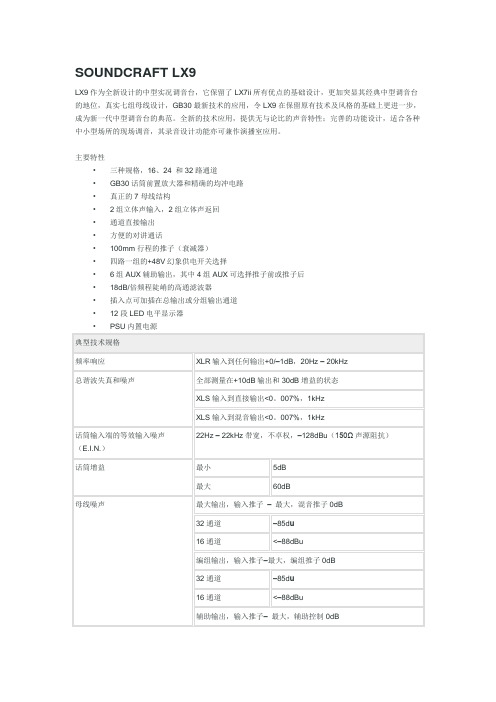
SOUNDCRAFT LX9
LX9作为全新设计的中型实况调音台,它保留了LX7ii所有优点的基础设计,更加突显其经典中型调音台的地位,真实七组母线设计,GB30最新技术的应用,令LX9在保留原有技术及风格的基础上更进一步,成为新一代中型调音台的典范。
全新的技术应用,提供无与论比的声音特性;完善的功能设计,适合各种中小型场所的现场调音,其录音设计功能亦可兼作演播室应用。
主要特性
•三种规格,16、24 和32路通道
•GB30话筒前置放大器和精确的均冲电路
•真正的7母线结构
•2组立体声输入,2组立体声返回
•通道直接输出
•方便的对讲通话
•100mm行程的推子(衰减器)
•四路一组的+48V幻象供电开关选择
•6组AUX辅助输出,其中4组AUX可选择推子前或推子后
•18dB/倍频程陡峭的高通滤波器
•插入点可加插在总输出或分组输出通道
•12段LED电平显示器
•PSU内置电源。
- 1、下载文档前请自行甄别文档内容的完整性,平台不提供额外的编辑、内容补充、找答案等附加服务。
- 2、"仅部分预览"的文档,不可在线预览部分如存在完整性等问题,可反馈申请退款(可完整预览的文档不适用该条件!)。
- 3、如文档侵犯您的权益,请联系客服反馈,我们会尽快为您处理(人工客服工作时间:9:00-18:30)。
2© Harman International Industries Ltd. 2003All rights reservedParts of the design of this product may be protected by worldwide patents.Part No. ZM0288Issue: 1Soundcraft is a trading division of Harman International Industries Ltd. Information in this manualis subject to change without notice and does not represent a commitment on the part of thevendor. Soundcraft shall not be liable for any loss or damage whatsoever arising from the use ofinformation or any error contained in this manual.No part of this manual may be reproduced, stored in a retrieval system, or transmitted, in anyform or by any means, electronic, electrical, mechanical, optical, chemical, including photocopyingand recording, for any purpose without the express written permission of Soundcraft.Harman International Industries LimitedCranborne HouseCranborne RoadPOTTERS BARHertfordshireEN6 3JNUKTel:+44 (0)1707 665000Fax:+44 (0)1707 660742IMPORTANTPlease read this manualcarefully before usingyour mixer for the first time.3ContentsINTRODUCTION5Featur Featureses 6W ar arranty ranty 7INST INSTALLA ALLA ALLATIONTION 9W ARNING10Pr Precautions and Safety Instr ecautions and Safety Instr ecautions and Safety Instructionsuctions 11General Precautions11Handling and Transport11Power Supplies & Cables11Signal Levels 11Mains Installation11General Wiring Procedures11Initial Wiring Considerations12Audio Wiring12Shielding12Points to Remember 13Setting Up & T Setting Up & Trr oubleshooting 14Initial set-up14Troubleshooting 14Connecting Leads16Audio Connector Pinouts17Dimensions 18BLOCK DIAGRAM19USING THE CONSOLE21Overview22Mono Input Channel23Stereo Input Channel27Master Section28Mark-up Sheet 30SPECIFICA SPECIFICATIONS TIONS 314INTRODUCTION5W ar arrantyranty1Soundcraft is a trading division of Harman International Industries Ltd.End User means the person who first puts the equipment into regular operation.Dealer means the person other than Soundcraft (if any) from whom the End User purchased the Equipment, provided such a person is authorised for this purpose by Soundcraft or itsaccredited Distributor.Equipment means the equipment supplied with this manual.2If within the period of twelve months from the date of delivery of the Equipment to the End User it shall prove defective by reason only of faulty materials and/or workmanship to such an extent that the effectiveness and/or usability thereof is materially affected the Equipment or the defective component should be returned to the Dealer or to Soundcraft and subject to the following conditions the Dealer or Soundcraft will repair or replace the defectivecomponents. Any components replaced will become the property of Soundcraft.3Any Equipment or component returned will be at the risk of the End User whilst in transit (both to and from the Dealer or Soundcraft) and postage must be prepaid.4This warranty shall only be available if:a) the Equipment has been properly installed in accordance with instructions contained inSoundcraft's manual; andb) the End User has notified Soundcraft or the Dealer within 14 days of the defect appear-ing; andc) no persons other than authorised representatives of Soundcraft or the Dealer haveeffected any replacement of parts maintenance adjustments or repairs to the Equipment;andd) the End User has used the Equipment only for such purposes as Soundcraft recom-mends, with only such operating supplies as meet Soundcraft's specifications and otherwise in all respects in accordance Soundcraft's recommendations.5Defects arising as a result of the following are not covered by this Warranty: faulty or negligent handling, chemical or electro-chemical or electrical influences, accidentaldamage, Acts of God, neglect, deficiency in electrical power, air-conditioning or humiditycontrol.6.The benefit of this Warranty may not be assigned by the End User.7.End Users who are consumers should note their rights under this Warranty are in addition toand do not affect any other rights to which they may be entitled against the seller of theEquipment.78INST ALLA TION For your own safety and toavoid invalidation of thewarranty please read thissection carefully.910W ARNINGTHIS UNIT MUST BE EARTHEDUnder no circumstances should the mains earth be disconnected from themains lead.The wires in the mains lead are coloured in accordance with the following code:Earth:Green and Yellow (Green/Yellow - US)Neutral:Blue (White - US)Live:Brown (Black - US)As the colours of the wires in the mains lead may not correspond with the coloured markings identifying the terminals in your plug,proceed as follows:The wire which is coloured Green and Yellow must be connected to the terminal in the plug which is marked with the letter E or by the earth symbol.The wire which is coloured Blue must be connected to the terminal in the plug which is marked with the letter N.The wire which is coloured Brown must be connected to the terminal in the plug which is marked with the letter L.Ensure that these colour codings are followed carefully in the event of the plug being changed.To avoid the risk of fire, replace the mains fuse only with the correct valuefuse, as marked on the rear panel.The internal power supply unit contains no user serviceable parts. Refer all servicing to a qualified service engineer, through the appropriateSoundcraft dealer.Pr Precautions and Safety Instructionsecautions and Safety Instrecautions and Safety InstructionsGeneral PrecautionsAvoid storing or using the mixing console in conditions of excessive heat or cold, or in positions where it is likely to be subject to vibration, dust or moisture. Do not use any liquids to clean the fascia of the unit: a soft dry cloth is ideal.Avoid using the console close to strong sources of electromagnetic radiation (e.g. video monitors, high-power electric cabling): this may cause degradation of the audio quality due to induced voltages in connecting leads and chassis.Caution! In all cases, refer servicing to qualified personnel. Handling and TransportThe console is supplied in a strong carton. If it is necessary to move it any distance after installation it is recommended that this packing is used to protect it. Be sure to disconnect all cabling before moving. If the console is to be regularly moved we recommend that it is installed in a foam lined flightcase. At all times avoid applying excessive force to any knobs, switches or connectors.Power CableAlways use the power supply cable supplied with the mixer: the use of alternative cables may cause damage and voids the warranty.W a r n i n g ! In the event of an electrical storm, or large mains voltage fluctuations, immediately switch off the mixer and unplug from the mains. Signal LevelsIt is important to supply the correct input levels to the console, otherwise signal to noise ratio or distortion performance may be degraded; and in extreme cases, damage to the internal) circuitry may result. Likewise, on all balanced inputs avoid sources with large common mode DC, AC or RF voltages, as these will reduce the available signal range on the inputs. Note that OdBu =0.775V RMS.Refer to the Specifications section for details of input and output levels.Mains InstallationGeneral Wiring ProceduresTo take full advantage of the excellent signal to noise ratio and low distortion of Soundcraft consoles, care must be taken to ensure that incorrect installation and wiring does not degrade the performance of the desk. Hum, buzz, instability and Radio Frequency interference can usually be traced to earth loops and inferior earthing systems. In some areas, especially heavily industrial areas, the incoming mains earth will not be adequate and a separate technical earth for all the audio equipment must be supplied. However, check with your local electricity supply company to ensure that safety regulations are not infringed or negated.The successful, hum free, installation of a system requires forethought, and the establishment of a set of ground rules, which must be consistently adhered to at all stages of installation.11Initial Wiring ConsiderationsFor optimum performance, it is essential for the earthing system to be clean and noise free, as all signals are referenced to this earth. A central point should be decided on for the main earth point system, and all earths should be 'star fed' from this point. It is common electrical practice to `daisy chain' the earths to all electrical outlets but this method is unsuitable for audio installations. The preferred method is to run an individual earth wire from each outlet, back to the system star point to provide a safety earth screen reference for each piece of equipment.A separate earth wire should also be run from each equipment rack and area, to the star point. This may or may not be used depending on circumstances, but it is easier to install in the first place, than later when problems arise.The location of the star point should be a convenient, easily accessible place, preferably at the rear of the console or in the main equipment rack.Install separate 'clean' and 'dirty' mains outlets, wired individually back to the incoming mains distribution box. Use the 'clean' supply for all audio equipment and the `dirty' supply for all lighting, etc. Never mix the two systems.If necessary, to provide sufficient isolation from mains borne interference, install an isolating transformer. This should be provided with a Faraday Shield which must be connected with earth.Never locate the incoming mains distribution box near audio equipment, especially tape recorders, which are very sensitive to electro-magnetic fields.Ensure that all equipment racks are connected to earth, via a separate wire back to the star point.Equipment which has unbalanced inputs and outputs may need to be isolated from the rack to prevent earth loops.Audio WiringHaving provided all equipment with power and earthing connections, consideration must be given to the method of providing audio interconnection and adequate screening of those interconnections. This must be done in a logical sequence to avoid problems and assist in the localisation of problem equipment.Connect the FOH or Monitor system to the console and check for any hum, buzz, or RFI. Only when you are satisfied with the quietness of the console and the PA system should you proceed with the next step.Connect stereo or multitracktape recorders, FX and foldback sends one at a time, checking and isolating any connection which degrades performance.Connect all other peripheral devices.Connect all microphone lines.By following this sequence much time and future trouble will be saved, and the result will be a quiet, stable system. ShieldingAudio equipment is supplied with a variety of input and output configurations, which must be taken into consideration when deciding where the screen connections should be made. There are three sources of unwanted signal being impressed on the screen, which are as follows:Extraneous electrostatic or electromagnetic fields.Noise and interference on the earth line.Capacitive coupling between the screen and signal wires.To minimise the adverse affects of the unwanted coupling to the signal wires, it is important that the screen is connected at one end only, i.e. the screen must not carry any signal) current. Any signal) on the wires within the screen will be capacitively coupled to the screen. This current will ultimately be returned to the source of the signal, either directly, if the screen is connected at the signal source end, or indirectly via the earthing system, if the signal is connected at the signal destination end. The indirect connection will cause an increase in high frequency cross-talk, and should be avoided wherever possible.Therefore, in general, always connect the shield only at the signal source end. In high RF areas, the screen can also be connected to earth via a 0.01 mF capacitor. This will present a short circuit at RF frequencies, thus lowering the effective shield impedance to ground. However, at low audio frequencies the reactance of the capacitor will be sufficiently high not to cause an earth loop problem.12Points to RememberIn all cases, use good quality twin screened audio cable. Check for instability at the output.Always connect both conductors at both ends, and ensure that the screen is only connected at one end.Do not disconnect the mains earth from each piece of equipment. This is needed to provide both safety and screen returns to the system star point.Equipment which has balanced inputs and outputs may need to be electrically isolated from the equipment rack and/or other equipment, to avoid earth loops.It is important to remember that all equipment which is connected to the mains is a potential source of hum and interference and may radiate both electrostatic or electromagnetic radiation. In addition, the mains will also act as a carrier for many forms of RF interference generated by electric motors, air-conditioning units, thyristor light dimmers etc. Unless the earth system is clean, all attempts to improve hum noise levels will be futile. In extreme cases there will be no alternative but to provide a completely separate and independent `technical earth' to replace the incoming 'noisy earth'. However, always consult your local electricity supply authority to ensure that safety regulations are not being infringed.1314Setting Up & T Setting Up & Trr oubleshooting Initial set-upOnce you have connected up your system (see the sections on connection and wiring earlier in this manual for guidance) you are ready to set initial positions for the controls on your mixer.Set up individual input channel as follows:Connect your sources (microphone, keyboard etc.) to the required inputs and release the MUTE switches. Note: Phantom powered mics should be connected before the 48V is switched on.Set Master faders at 0, input faders at 0, route the channels to MIX and set power amplifier level to suit the application.Provide a typical performance level signal and press the PFL button on the first channel, monitoring the level on the bargraph meters.Adjust the input gain until the meter display is in the amber section, with occasional peaks to the first red LED at a typical maximum source level. This allows sufficient headroom to accommodate peaks and establishes the maximum level for normal operation (but see note below).Repeat this procedure on other channels as required.Listen carefully for the characteristic sound of `feedback’. If you cannot achieve satisfactory input level setting without feedback, check microphone and speaker placement and repeat the exercise. If feedback persists, it may be necessary to use a Graphic Equaliser to reduce the system response at particular resonant frequencies.Note: The initial settings should only be regarded as a starting point for your mix. It is important to remember that many factors affect the sound during a live performance, for instance the channel EQ settings or even the size of the audience!You are now ready to start building the mix and this should be done progressively, listening carefully for each component in the mix and watching the meters for any hint of overload. If this occurs, back off the appropriate Channel Fader slightly until the level is out of the red segments, or adjust the Mix Master Faders. This procedure will ensure that the mixer is set up correctly, with adequate headroom. If more amplification is needed, adjust the power amplifier level controls.TroubleshootingN o P o Poo w er Is the mains supply present?Is the mains lead firmly connected?Check the mains fusingIf only one of the power indicators is illuminated, consult your Soundcraft dealerCondenser Mic N Condenser Mic No o t W t Wor or orkingking Is the 48V turned on?Is the mic plugged into the Mic input?Is the mic cable a balanced 3-wire type?15Me Met t er ers no s no s not sho t sho t showing an wing an wing any signaly signal Has the input gain been set correctly? (see above.)Is the source connected to the appropriate input socket for the level of signal?Do you have something connecetd on the Inserts, and is that external device switched on?Are the Master faders set at max., are input faders set high enough and is the channel routed to the output being monitored?Is the MUTE switch released on the relevant channels?Is the appropriate monitor select switch pressed?Is there a PFL/AFL pressed on another channel?No Mix outputCheck that the Mix Master Fader is up?Check that the 2TK REPLACES MIX switch is released?N o Monit o Monitor outputor output Is a headphone jack plugged in?Is the Monitor + Phones control set high enough?Is the appropriate monitor select switch pressed?Headphones Dis Headphones Dist t or ortingting Are the headphones less than 200Ω impedance?Is the Monitor + Phones level set too high?Connecting Leads16Audio Connector Pinouts1718DimensionsBLOCK DIAGRAM19USING THE CONSOLE2123Mono Input Channel1 - MIC INPUTThe mic input accepts XLR-type connectors and is designed to suit a wide range ofBALANCED or UNBALANCED signals. Professional dynamic, condenser or ribbon micsare best because these will be LOW IMPEDANCE. You can use low-cost HIGH IMPEDANCEmics, but the level of background noise will be higher. If you press the 48V switch downthe socket provides a suitable powering voltage for professional condenser mics (this isalso known as Phantom Power).ONLY connect condenser microphones with the48V powering OFF (switch UP), and ONLY turn the48V powering on or off with all output fadersDOWN, to prevent damage to the mixer orexternal devices.TAKE CARE when using unbalanced sources,which may be damaged by the phantom powervoltage on pins 2 & 3 of the XLR connector.Unplug any mics if you want to use the LINE Input. The input level is set using the GAINknob.2 - 48V (Phant 2 - 48V (Phantom P om P om Poo w er)Many professional condenser mics need an external powering voltage, normally 48V,also known as PHANTOM POWER. This is a method of sending a powering voltage downthe same wires as the mic signal. Each switch supplies the 48V power to four MIC inputs.The adjacent LED illuminates when the power is active.DO NOT USE unbalanced mics with 48V switchedon as they may be damaged by the phantompower voltage. Balanced dynamic mics and leadscan normally be used with 48V switched on(contact your microphone manufacturer forguidance)Mics should always be plugged in, and all outputfaders set to minimum before switching 48V ON toavoid damage to external equipment3 - LINE INPUTAccepts 3-pole `A’ gauge (TRS) jacks. Use this high impedance input for sources otherthan mics, such as keyboards, drum machines, synths, tape machines or guitars. Theinput is BALANCED for low noise and top quality from professional equipment, but youcan use UNBALANCED sources by wiring up the jacks as shown, although you shouldthen keep cable lengths as short as possible. Unplug anything in the MIC input if youwant to use this socket. Set the input level using the GAIN knob.246 - INSERT POINTThe unbalanced, pre-EQ insert point is a break in the channel signal path, allowing limiters, compressors, special EQ or other signal processing units to be added in the signal path. The Insert is a 3-pole ‘A’ gauge jack socket which is normally bypassed. When a jack is inserted, the signal path is broken, just before the EQ section. The Send may be tapped off as an alternative pre-fade, pre-EQ direct output if required, using a lead with tip and ring shorted together so that the signal path is not interrupted.7 - DIRE7 - DIRECT OUTPUTCT OUTPUTChannels 1-8/1-16/1-24 (see block diagram) have a dedicated Direct Output which allows direct connection to external devices, for example to feed Tape Machines or effects units.The pre-fade direct output level may be monitored by pressing the PFL switch on the appropriate channel to feed the pre-fade signal to the monitors and the bargraph meters.8 - DIR. PREThe Direct Outputs are normally set POST-FADER for use as effects sends or to provide fader control of recording levels in a studio recording application. For live recording the outputs can be individually changed to PRE-FADER by pressing this switch, so that the direct output level remains unaffected by fader settings for the main PA mix.9 - EQU9 - EQUALISERALISERThe Equaliser (EQ) allows fine manipulation of the frequency bands, and is particularly useful for improving the sound in live PA applications where the original signal is often far from ideal and where slight boosting or cutting of particular voice frequencies can really make a difference to clarity.This knob sets how much of the source signal is sent to the rest of the mixer. Too high, and the signal will distort as it overloads the channel. Too low, and the level of any background hiss will be more noticeable and you may not be able to get enough signal level to the output of the mixer.See `Setting Up & Troubleshooting’ on page 20 to learn how to set GAIN correctly.5 - 15 - 100Hz HI-P00Hz HI-P00Hz HI-PASS FILASS FILASS FILTERTERPressing this switch activates a steep 18dB per octave filter which reduces the level of bass frequencies only. Use this in live PA situations to clean up the mix, reducing stagerumble or ‘popping’ from microphones.25Turn clockwise to boost high (treble) frequencies (12kHz and above) by up to 15dB,adding crispness to cymbals, vocals and electronic instruments. Turn anticlockwise tocut by up to 15dB, reducing hiss or excessive sibilance which can occur with certaintypes of microphone. Set the knob in the centre-detented position when not required.MID EQ (HMID & LMID)There are two pairs of knobs which work together to form HI and LO MID frequency EQsections. The lower knob in each pair provides 15dB of boost and cut, just like the HFEQ knob, but the frequency at which this occurs can be set by the upper knob over arange of 550Hz to 13kHz (HMID) or 80Hz to 1.9kHz (LMID). This allows some trulycreative improvement of the signal in live situations, because the mid bands cover therange of most vocals. Listen carefully as you use these controls together to find howparticular characteristics of, for instance, a vocal signal can be enhanced or reduced.Set the gain (lower) knob to the centre-detented position when not required. Note: Qis set at 1.5.LF EQTurn clockwise to boost low (bass) frequencies (60Hz and below) by up to 15dB,adding warmth to vocals or extra punch to synths, guitars and drums. Turn anticlockwiseto cut low frequencies by up to 15dB for reducing hum, stage rumble or to improve amushy sound. Set the knob to the centre-detented position when not required.10 - EQ S 0 - EQ SWIT WIT WITCHCH The EQ switch bypasses the Equalisation section when released. Alternately pressingand releasing the switch provides an easy way of comparing the equalised andunequalised signals.11 - A 1 - AUX SENDSUX SENDS These are used to set up separate mixes for FOLDBACK, EFFECTS or recording, and thecombination of each Aux Send is mixed to the respective Aux Output at the rear of themixer. For Effects it is useful for the signal to fade up and down with the fader (this iscalled POST-FADE), but for Foldback or Monitor feeds it is important for the send to beindependent of the fader (this is called PRE-FADE). All Aux Sends are muted with theother channel outputs when the MUTE switch is pressed.All six Aux Sends are POST-EQ, unless the EQ is bypassed using the EQ switch (seeabove) and are normally POST-FADE for use as effects sends or additional submixes.Aux’s 1 & 2 and 3 & 4 may if required be switched in pairs to PRE-FADE by pressingthe respective PRE switch, for use as foldback or monitor feeds. Aux’s 5 & 6 alwaysremain POST-FADE.12 - P 2 - PANAN This control sets the amount of the channel signal feeding the Left and Right MIXbuses, allowing you to move the source smoothly across the stereo image. When thecontrol is turned fully right or left you are able to route the signal at unity gain to eitherleft or right outputs individually.13 - MUTEAll outputs from the channel except inserts are active when the MUTE switch is releasedand muted when the switch is down, allowing levels to be pre-set before the signal isrequired.2614 - F4 - FADERADERThe 100mm FADER allows precise balancing of the various source signals being mixed to the Master Section. You get most control when the input Sensitivity is set up correctly, giving full travel on the fader. See the `Setting Up & Troubleshooting’ section on page 20 for help in setting a suitable signal level.15 - R5 - ROUTINGOUTINGThe channel signal may be routed to the main stereo MIX or pairs of group busses (1-2, 3-4) by pressing the respective switches, with the channel signal fed proportionately to left (1, 3) or right (2, 4) depending on the position of the PAN control (11). The channel signal may also be routed to the separate centre (mono) bus by pressing the C switch, unaffected by the position of the PAN control.16 - PFL/PEAKWhen the latching PFL switch is pressed, the pre-fade, post-EQ signal is fed to the headphones, control room output and meters, where it replaces the selected monitor source. The adjacent LED lights to identify the selected channel and the PFL/AFL LED on the Master section illuminates to warn that a PFL is active. This is a useful way of listening to any required input signal without interrupting the main mix, for making adjustments or tracing problems.When the PFL switch is released the LED serves as a PEAK indicator which illuminates approximately 4dB before clipping to give warning of a possible overload. The signal is sampled both after the HF EQ and also POST EQ.Stereo Input Channel Array 1 - INPUT J1 - INPUT JA A CKSThese high impedance inputs accept 3-pole `A’ gauge (TRS) jacks. Use these inputs for sources such as keyboards, drum machines, synths, tape machines or returns from processing units. The inputs are BALANCED for low noise and top quality from professional equipment, but you can use UNBALANCED sources by wiring up the jacks as shown in the “Connecting Leads” section on page 22 in this manual, although you should then keep cable lengths as short as possible to prevent ‘hum’ being induced into the sound system. Mono sources may be used by plugging into the left jack only.AIN2 - G2 - GAINThe GAIN control sets the input level to the channel, allowing matching to a wide range of line level sources.3 - EQUALISER3 - EQUALISERHF EQTurn clockwise to boost high (treble) frequencies, adding crispness to percussion from drum machines, synths and electronic instruments. Turn anticlockwise to cut these frequencies, reducing hiss or excessive brilliance. Set the knob in the centre-detented position when not required. The control has a shelving response giving 15dB of boost or cut at 12kHz and above.LF EQTurn clockwise to boost low (bass) frequencies, adding extra punch to synths, guitars and drums. Turn anticlockwise to reduce hum, boominess or improve a mushy sound. Set the knob to the centre-detented position when not required. The control has a shelving response giving 15dB of boost or cut at 60Hz and below.UX SENDS4 - A4 - AUX SENDSThese are used to set up separate mixes for FOLDBACK, EFFECTS or recording, and the combination of each Aux Send is mixed to the respective Aux Output at the rear of the mixer. The sends are always PRE-FADE which is most appropriate for Foldback or Monitor feeds, but note that the Line Inputs on pairs of Mono channels may be used as alternative stereo inputs if post-fade sends are essential for effects.5 - LEVELThe rotary level control adjusts the overall level of the signal which is fed to the Mix or selected pair of Groups.OUTING6 - R6 - ROUTINGThe Stereo channel signal is fed either to a pair of Subgroups (switch UP) or the stereo Mix (switch DOWN), at a level set by the LEVEL control. Stereo 1 feeds to Subgroups 1 & 2, Stereo 2 feeds to Subgroups 3 & 4.7 - PFLWhen the latching PFL switch is pressed, the pre-fade, post-EQ signal is fed in mono to the headphones, control room output and meters, where it replaces the selected monitor source. The PFL/AFL LED on the Master section illuminates to warn that a PFL is active.The Left and Right meters display the PFL signal in mono.27。