诺方舟NF-308使用说明书
EXHAUSTO VEX308 EXact 产品说明书
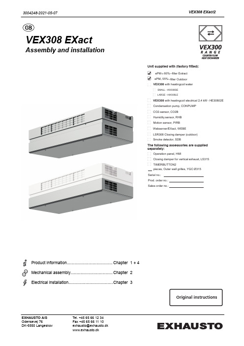
VEX308 EXactAssembly and installationProduct information........................................Chapter1 + 4Mechanical assembly.....................................Chapter2Electrical installation.......................................Chapter 3Unit supplied with (factory fitted):ePM 10 60%--filter Extract ePM 1 55%--filter Outdoor VEX308 with heatingcoil waterSMALL - HW308SELARGE - HW308LEVEX308 with heatingcoil electrical 2,4 kW - HE30802E Condensation pump, CONPUMP CO2-sensor, CO2B Humidity sensor, RHB Motion sensor, PIRB Webserver/EXact, WEBE LSR308 Closing damper (outdoor) Smoke detector, SDBThe following accessories are supplied separately:Operation panel, HMIClosing damper for vertical exhaust, LS315 TIMERBUTTON2pieces, Outer wall grilles, YGC Ø315Serial no.: Prod. order no.: Sales order no.:Original instructions3004248-2021-05-07VEX308 EXact2EXHAUSTO A/S Odensevej 76DK-5550 LangeskovTel. +45 65 66 12 34Fax +45 65 66 11 10********************www.exhausto.dk1.Product information1.1.Location in room....................................................................................................51.1.1.Optimum location ............................................................................................51.1.2.Space requirements ........................................................................................51.2.Application.............................................................................................................61.3.Designations used in these instructions.............................................................61.3.1.Simplified diagram............................................................................................61.4.Description.............................................................................................................81.4.1. Construction of the VEX unit...........................................................................81.4.2.VEX unit, parts and materials...........................................................................91.5.Principal dimensions. (10)Ceiling mounting - visible ..............................................................................101.5.1.Partly integrated ceiling mounting (11)2.Mounting2.1.Unpacking.............................................................................................................122.2.Wall mounting (accessories for some models).................................................122.2.1.Requirements for wall ...................................................................................122.2.2.Instructions and warnings .. (12)Wall mounting step by step (12)2.3.Ceiling mounting..................................................................................................132.3.1.Ceiling requirements......................................................................................132.3.2.Instructions and warnings .............................................................................132.3.3.Ceiling mounting step by step .......................................................................142.4.Partly integrated mounting.................................................................................142.5.Connection of condensation outlet....................................................................152.5.1.Condensation outlet guide channels (if condensation pump is mounted)......152.6.Connection of water heating coil (option).........................................................152.6.1.Connecting the water. (15)3.Electrical installation3.1.Supply voltage and fuses....................................................................................163.1.1.Position of power socket.. (16)Maximum power consumption ......................................................................163.1.2.Permanent installation (16)4.Technical data4.1.Weight, corrosion class, temperature ranges, etc............................................174.2.Electrical data for unit without heating coil......................................................174.3.Data for unit with heating coil.............................................................................174.3.1.Electric heating coil........................................................................................174.3.2.Water heating coils.........................................................................................184.3.3.MVM motor valve ..........................................................................................194.4.Condensate pact filters.....................................................................................................194.6.Capacity diagram and diagram for specific power consumption...................204.6.1.Capacity diagram...........................................................................................204.6.2.Capacity diagram - mounting on "duct system" ............................................214.6.3.Specific power consumption, SFP . (22)2/24Symbols, terms and warningsProhibition symbolFailure to observe instructions marked with a prohibition symbol may result in serious or fatal injury.Danger symbolFailure to observe instructions marked with a danger symbol may result in personal injury and/or damage to the unit.ScopeThis instruction manual is for use with EXHAUSTO VEX-type air handling units.Please refer to the product instructions regarding accessories and extra equip-ment.The instructions must be fully observed to ensure personal safety and to protect the equipment and ensure its correct operation. EXHAUSTO A/S accepts no liabil-ity for accidents caused by equipment not used in accordance with the manual’s instructions and recommendations.Prohibited usesThe VEX unit is not to be used to transport solid particles or in areas where there is a risk of explosive gases.Warnings:StartupThe unit must not be started up until it is fully mounted with door and duct connections.Opening the unitDo not open the service door until the supply voltage has been disconnected (remove plug from socket) and the fans have stop-ped.Duct termination atwallMount a permanent protective mesh to the exhaust and outdoor air connection, using a mesh size of max. 20 mm. For example,use the EXHAUSTO outer wall grilles.Information plateThe VEX unit information plate shows:●VEX model (1)●Production order no. (2)12NB:Always have the production number ready when contacting EXHAUSTO A/S.3/24NB:Find the newest version of the publication by searching for the order number on the EXHAUSTO website under DownloadsSupply air/extract air This instruction manual uses the following terminology:●Supply air (air blown in)●Extract air (air removed)●Outdoor air●Exhaust airFront page - Acces-sories The front page of the instruction manual contains a checklist, detailing the acces-sories delivered with the VEX unit.4/241. Product information1.1 Location in room1.1.1 Optimum locationAs far as possible the unit should be located in the middle of the wall.Avoid placing the VEX308 on the long side of narrow rooms.1.1.2 Space requirements0The sketch shows how much space is required under the unit for opening the door and servicing. The dimensions at the sides of the unit indicate the minimum clear-ance for optimum servicing conditions.R D 13146-015/241.2 ApplicationComfort ventilation EXHAUSTO's VEX308 unit is used for comfort ventilation in frost-free single-room locations. The VEX unit is designed for wall or ceiling mounting and must be usedas such.Operating temperature range for unit see section "Technical data".1.3 Designations used in these instructions1.3.1 Simplified diagramWith integral waterheating coil, HCW(top view)6/24With integral elec-tric heating coil,HCE (top view)7/241.4 Description1.4.1 Construction of the VEX unitThe drawing below shows an overview of the VEX unit construction. Details of HCW and HCE are viewed from below:EC H WC HR D 13198-038/241.4.2 VEX unit, parts and materialsCabinet The exterior of the cabinet is made of Aluzinc® and the cabinet is insulated with20 mm sound insulation material.Fans The unit contains two centrifugal fans with EC motors for extract air and supply air.Counter flow heat exchanger The unit's counterflow heat exchangers are made of aluminium and are highly effi-cient. The counterflow heat exchangers can be taken out and cleaned.Filters The unit includes integral compact filters on both extract air and supply air sides, the ePM10 60% and ePM1 55% filter respectively.Condensation out-let The condensation tray is located under the counterflow heat exchangers. There will only be a condensation outlet from the condensation tray if a condensation pump has been purchased. See also section on connection of condensation out-let.Bypass damper The unit has a variably adjustable bypass damper for temperature regulation and de-icing of counterflow heat exchangers during operation. See operating and serv-ice instructions for further description of de-icing.9/241.5 Principal dimensionsCeiling mounting - visibleR D 13126-02AA10/241.5.1 Partly integrated ceiling mountingR D 13446-03A-A3004248-2021-05-07Product information2. Mounting2.1 UnpackingStandard delivery●VEX308 unit●Housing panels packed separately●Wall brackets premounted on VEX (accessories on some models)●Ceiling brackets, supplied separatelySee information about included accessories on front page of these instructions. Any included ac-cessories2.2 Wall mounting (accessories for some models)2.2.1 Requirements for wallFor wall mounting, it is a requirement that the wall is:●flat●vibration-resistant●plumb (max. 4 mm per metre)●in a material suitable for safe mounting of the unit2.2.2 Instructions and warningsDimensioning Wall mountings must be dimensioned from the unit's weight.Mounting must be carried out in accordance with the ProjectManager's instructions.For wall mounting the two front ceiling brackets should also beused.Suspension The unit must be suspended with the door facing the floor. Theunit must not be mounted in any other way.The housing panels must be fixed with the accompanyingscrews.Wall mounting step by stepSee the attached installation guide (3004368).NB The dimensions of the wall template will match when held right up to the ceiling.2.3 Ceiling mounting2.3.1 Ceiling requirements0When fitting the unit to a ceiling, the ceiling must be:●flat●vibration-resistant ●horizontal●designed to bear the weight of the unit2.3.2 Instructions and warnings DimensioningCeiling mountings must be dimensioned from the unit's weight.Mounting must be carried out in accordance with the Project Manager's instructions.SuspensionThe unit must be suspended with the door facing the floor. The unit must not be mounted in any other way.The housing panels must be fixed with the accompanying screws.2.3.3 Ceiling mounting step by stepSee the attached installation guide (3004368).*) To be carried out in the event that the VEX has not been ordered with exhaust/outdoor air connection via the ceiling.2.4 Partly integrated mountingInstallationInstallation of the partly integrated VEX is carried out as described in sections 2.2.and 2.3.Access to control systemWhen carrying out installation, ensure there is access to the control system. EX-HAUSTO recommends that the part of the ceiling next to the control system can be removed.NBThe partly-integrated VEX extracts a small amount of air above the suspended ceiling, which can cause the filter to soil more quickly than usual. EXHAUSTO rec-ommends leaving a 10 mm gap between the cabinet and the suspended ceiling.2.5 Connection of condensation outlet2.5.1 Condensation outlet guide channels (if condensation pump is mounted)Wall-mounted VEX On wall-mounted units the condensation outlet is positioned with the outlet pass-ing through the exhaust duct.Ceiling-mounted VEXOn ceiling-mounted units the condensation outlet is led through the internal guidechannels (rubber sleeves) out of the unit to the drain.The penetrations in the unit must be executed so as to retain air tightness.Condensate pump (optional/accesso-ry)For technical data, see final section.2.6 Connection of water heating coil (option)2.6.1 Connecting the water Valves for water connectionIt is recommended that shut-off valves are mounted on both water connections toenable the flow to be interrupted for servicing.The dimensioning of valves, pipes, etc. and the connection of the water heating coil must always be carried out by authorised fit-ters in accordance with applicable regulations and legislation.Position of bleeder valve on VEX See keyed drawing for position of internal bleeder valve.Automatic bleeder valveIf the water connection is executed with vertical riser, so the heating coil in the VEX308 is the highest point in the pipe system, it is recommended that an auto-matic bleeder valve is fitted at the highest point on the supply and return pipes.3. Electrical installation3.1 Supply voltage and fuses3.1.1 Position of power socketThe supply cable is fitted with a 230V plug and can thus be connected to a powersocket.Fit the power socket for the supply voltage close to the VEX unit and preferably within the easy reach of users of the room.Maximum power consumptionFuses The installation must be protected with a max. 16A fuse.3.1.2 Permanent installationIf the plug is cut off and the cable mounted in a permanent installa-tion, an isolation switch must be established at the time of installa-tion.Permanent installation must be carried out by an authorised electri-cian.3004248-2021-05-07Electrical installation4. Technical data4.1 Weight, corrosion class, temperature ranges, etc.WeightDoor25.5 kgCounter flow heat exchanger 2 x 11 kgMotor section 2 x 6.0 kgTotal weight184.5 kg incl. HW308SEPartly integrated203.0 kg incl. HW308SE Corrosion class,cabinet Corrosion class Corrosion class C4 in accordance with EN ISO 12944-2Temperature rangesOutdoor air temperature-40 - +40°CAmbient temperature (operating)-30 - +40ºCAmbient temperature when not in operation (storage, transport)-40 - +60ºCThe temperature ranges given are dependent on the type of installation, humidity,airflow, the balance between airflows, ducts and insulation and room temperature.If using pre-heating coils, the ambient temperature can be reduced.At temperatures below -25˚C, use of a thermostatically controlled heater in auto-mated control box is recommended.4.2 Electrical data for unit without heating coilVoltage 1 x 230 V+N+PEMaximum output575 WMaximum power consumption 2.5 A4.3 Data for unit with heating coil4.3.1 Electric heating coilElectrical data forVEX with electric heating coilHE30802E Voltage 1 x 230 V+N+PE Maximum output, HE30802E2975 W Maximum power consumption12.9 AData, thermal cut-out Thermal fuse, TSA7070 ℃Thermal fuse, TSA9090 ℃Contact type NC (Normally closed)Maximum load 1.6 A @ 24 V DC NB Motors and heating coils may not be interrupted/switched off via OH70 and OH904.3.2 Water heating coilsElectrical data forVEX with water heating coil HCW Voltage 1 x 230 V+N+PE Maximum output575 W Maximum power consumption 2.5 AWater heating coildataOutput, K VS mv.Conditional upon: Supply temperature of water t F= 50°C and ΔT = 20K.4.3.3 MVM motor valve4.4 Condensate pumpCondensate pumpMaximum power consumption16WMaximum lifting height 5.0mHose dimension dia. 4/8 mm 4.5 Compact filtersFilter data, VEX308,filter data accordingto ISO168904.6 Capacity diagram and diagram for specific power consumption4.6.1 Capacity diagram Read control volt-ageWhen an EXact control panel (HMI) is connected to the VEX unit, the control volt-age can be read from menu 2.3 and thereby give a reasonable reading of airflow on the diagram. Conditional upon: 750 m 3/h at 35 Pa.1) Visible unit max. 750 m 3/h2) Partly integrated unit max. 650 m 3/h4.6.2 Capacity diagram - mounting on "duct system"1) Visible unit max. 750 m3/h2) Partly integrated unit max. 650 m3/h21/244.6.3 Specific power consumption, SFP1) Visible unit max. 750 m3/h2) Partly integrated unit max. 650 m3/h22/243004248-2021-05-0723/24。
世光L-308S测光表使用中文说明书
ISO Button
ISO设定键
Strap Eyelet
挂绳眼
Flash Synchro Terminal
闪光灯同步线接口
Battery Compartment Cover
电池盒盖
Synchro Terminal Cap
同步接口盖
Lumidisc
WARNING
q Please place in a location where an infant cannot reach and accidentally get the strap wrapped around his or her neck. There is danger of strangulation.
1. Attach the strap ..绑....挂....绳................................................................ 3 2. Inserting the battery .安....装.....电....池..................................................... 3 3. Checking battery capacity .检....查....电....量............................................. 4 4. Replacing battery during measurement .更....换....电....池........................ 4 5. Auto Power OFF function 自.....动....关....机....功.....能...................................... 5 6. Setting ISO film speed .设....定....I.S...O....感....光....度....................................... 5 4. Basic Operation 基.....本....操....作................................................................ 6 1. Incident or reflected light measuring 入.....射....或....反....射.....测....光................ 6 2. Setting measuring mode 设.....定....测....光....模.....式...................................... 6 3. When set for incident light .入....射....式.....测....光....................................... 8 4. When set for reflected light .反....射.....式....测....光...................................... 9 5. Measurement .测....光......................................................................... 10 1. Measuring Ambient Light .现....场....光....测.....光....................................... 10
TK-308(1)的深层操作说明

TK-308(1)的深层操作TK208、308对讲机调整一、频率范围:;TK208:150MHZ;TK308:450MHZ二、本机程序主要采用三大模式:频率设定模式;维修模式;用户模式。
1.频率设定模式:在这个模式中,可设定各信道的频率,还可以设定各种功能和工作参数,打开电源,虽然可以看到显示频率,但是不能接收和发射。
如:***?**2.维修模式:在这个模式中,显示屏显示频率数值,可以进行接收和发射。
如:一***?**3.用户模式:这个模式是用户通常使用的模式,打开电源显示屏显示存储信道号码,在这个模式中可以使用的功能是在频率设定模式中所设定的。
如:CH*三、本机出厂状态:打开电源,便进入频率设定模式,必须在此模式下设定信道和功能后,才可以进入用户模式使用。
四、设定信道:MONI键,有光标"一"闪烁,旋编码开关,频率以"MHZ"为单位增减,再接一次MONI键光标消失,旋编码开关,频率以" KHZ"为单位增减,选定所需要的频率。
按一次"CSET"键,出现**闪烁,旋编码开关,选择所需要的信道(信道范围00-39,再按一次"CSET"键,闪烁消失,这时接收频率已写入所选择的信道;按方法1选定发射频率,按一次"CSET"键,出现"*闪烁,按住PTT再按CSET键,闪烁消失,这时发射频率已写入所选择的信道。
(注:如某一信道接收频率未写或未写进,发射频率就不能写入。
)在频率模式下,按REV键,显示±***。
** **显示内容为接收频率及信道号码,再按"CEST"键,显示R±***。
** **显示内容为发射频率及信道号码以上两次确认说明信道的接收和发射都已设定,如设定两个或两个以上信道,旋编码开关,所写入频率及信道将显示出来。
四、模式之间相互转换12返回到频率模式。
KH-308 说明书
KH-308 说明书目录一、注意事项………………………………………………二、终端设备的组成………………………………………三、终端主要功能…………………………………………四、功能实现必备条件……………………………………五、终端设备接线图………………………………………六、终端设备的安装………………………………………七、应用范围………………………………………………八、终端设备参数…………………………………………注意事项:1、用户安装设备前请仔细阅读本说明书。
2、安装前请先插入SIM卡,确保SIM卡没有设置密码,否则设备无法正常工作。
3、请先确认所有设备和连接线连接正确后再接主机电源。
切勿在主机上电的情况下安装或拆卸。
如发现有遗漏线或误接,请先切断电源,否则容易损坏设备。
4、本设备为无线通讯设备,进入油库和危险品场所前请切断主机电源。
5、本设备工作电压为9V-30V,请在工作电压范围内使用。
6、您的GPS车载终端的主机是一个低功率的无线发射机和接收机,它在使用中接收并发送射频信号。
7、为了避免电磁干扰或配置不兼容,请你贴有通知的场所按规定停止使用设备。
GPS定位终端终端设备的组成:1.终端主机(如图):终端指示灯:终端设备有红色和蓝色指示灯。
在给设备通上电源后,终端设备的红色指示灯会亮十几秒,然后进入每两秒闪一下,表示设备进入工作状态。
红色指示灯快速的闪表示终端设备正在通信。
蓝色指示灯两秒闪一下表示GPS模块在待机,蓝色指示灯一直不亮,表示GPS模块在工作,但还没有定位到,蓝色指示灯一直亮,表示GPS模块在工作,并且已经定位到。
终端主要功能:A、定位跟踪:通过平台或手机对终端设备进行时时定位,了解设备运行状态。
定位平台根据客户要求确定。
B、紧急触发报警:在安装有终端设备的车辆发生紧急情况时,发出报警求助。
C、远程控制油路和电路:随时随地通过手机短信控制安装有终端设备的车辆的油路和电路。
D、远程监听:拨打终端设备中的手机号码,接通后即可随时随地监听终端设备周围5米范围内的声音。
诺瓦科技LED接收卡MRV308产品说明书

间隔 3s 快闪 3 下
接收卡正常工作,网线连接正常,无视频源输 入。
间隔 0.2s 快闪
正常工作状态下程序加载失败,进入备份工作状 态。
5
接收卡 MRV308 产品说明书
电源指示灯 (红灯)
常亮
4.4 数据接口定义
供电后常亮。
4 硬件结构
司
公
限
电 瓦 诺 安 西
iii
接收卡 MRV308 产品说明书
1 安全说明
1 安全说明
司
公 本章介绍接收卡 MRV308 的安全说明,目的是保证产品的存储、运输、安装和使用安
全。安全说明适用于所有接触和使用产品的人员。首先请注意以下几点:
请阅读所有说明。 请保留所有说明。 请遵循所有说明。
安 只有通过培训的专业人员才可以安装产品。
西
禁止带电插拔。 请确保箱体安全接地。
请佩戴防静电护腕,穿戴绝缘手套。
请勿将产品安装在震动多或强的环境中。
请定期除尘。
请勿擅自维修产品,您可以随时联系诺瓦科技。
请使用诺瓦科技的同款产品进行备件更换。
技有
尺寸
科 144.0mm×91.5mm×16.0mm
净重 认证信息
子 85.5g
通过 RoHS 认证
瓦电 包装信息
单卡标配静电袋和防撞泡沫。 包装箱尺寸:650.0mm×500.0mm×200.0mm,每箱 100 张卡。
诺
安
西
10
西 编号
说明
1
HUB75 接口
2
电源插座
3
D1,状态指示灯
4
D2,电源指示灯
5
308-a2使用说明书

3108-A2电子台秤使用说明书太原太航电子科技有限公司目录一.概述 (3)二.技术性能 (3)三.使用 (4)四.键说明 (4)五.基本功能 (4).计价模式 (4).计数模式 (5).百分比模式 (6)六.参数设定 (6)七.错误报警及处理 (7)八、串口通讯协议 (8)九、出厂设置 (9)十、注意事项 (9)十一、三包规定 (9)一、概述主要特点:.符合电子计价秤国标中的计量性能及功能要求.分辨率可调,最大为1/15000.采用LED显示,显示位数16位.键盘设计:轻触键盘.RS232通讯口.计价、计数、百分比互相转换功能.千克、磅单位转换的功能.自动键盘标定重量.累计重量、金额及数量之功能.具有单重取样功能.具有百分比取样功能.具有单重及百分比取样不足报警功能.具有重量、金额、计数定量报警功能.具有设置量程、精度、零跟速度、通讯内容等功能.备有蓄电池,能进行交直流切换,蓄电池放电时间大于20小时。
自动充电,充电过程中指示灯显示,可自动检测电压,电压不足情况下可提供欠压报警。
二、技术性能:(1)型号:3108-A2(4)显示:16位LED显示。
重量:5位、单价: 5位、金额: 6位(5)额定电压:AC220V+10%-15% 50HZ;(6)额定功率:交流10W(7)环境温度:工作 0-40℃储藏 -10℃-55℃(8)湿度:相对湿度不大于90%(9)外形及重量:尺寸:370(长)x350(宽)x115(高)净重:约6.3kg三、使用⑴按秤电源开关,即开机。
⑵自检0-9显示,以检查显示是否正常。
显示结束后,进入称重状态,此时所有窗口显示零,零位指示灯亮,计价指示灯亮⑶工作结束时关闭电源开关。
⑷与计算机相接时,应使用同一电源四、键说明⑴【置零】秤重前如重量显示不为零,说明秤偏离零位或秤台上有残余物,此时可按【置零】键,零位指示灯亮,⑵【去皮】把包装或容器置于秤盘上,重量窗显示稳定后按【去皮】键,去皮指示灯亮,此时再放重物,则只显示重物的重量。
上海英盛EN-308红外说明书

EN-308红外线气体分析仪使用说明书上海英盛仪器有限公司Shanghai ENCEL Instrument Co.LTDEN-308红外线气体分析仪说明书目录1.概述 2 2.主要技术特性 3 3.工作原理7 4.仪器组成9 5.安装与接线10 6.仪器运行12 7.操作说明13 8.参数设定和校正24 9.日常维护33 10.贮存和保修34 11.成套产品清单34 12.快速查阅索引35敬告用户:EN-308红外线气体分析仪说明书在使用仪器前请仔细阅读本说明书●通入仪器的气体必须为干燥洁净气●必须保证仪器的进气压力不大于0.02Mpa1.概述EN-308型红外线气体分析仪采用了先进的检测技术和微处理机技术,具有数字化信息处理、人机对话、自动操作提示、大屏幕LCD显示、上下限报警、标准信号输出等功能。
可连续分析各种混合气体中的CO、CO2、CH4、NH3、NO、SO2等气体浓度,广泛适用于石化、化肥、空分、冶金、建材、电厂等工业生产流程气体在线分析,也可用于环保监测、卫生防疫、农业和科研等领域。
EN-308红外线气体分析仪外形图EN-308红外线气体分析仪说明书仪器特点●检测器采用前后气室结构,大大提升了仪器的选择性,交叉干扰小;●采用振幅调制技术,共模抑制能力强,零点漂移小,稳定性好;●全密封光路,不受环境气氛的影响;●包封红外光源,稳定性极高;●镀金测量气室耐腐蚀强;●大屏幕LCD液晶显示、全中文操作菜单,人机对话、自动提示操作步骤;●自动检测光源电压、本底基准电压等工作参数;●双量程自动转换(选项),计算机软件线性化处理;●具有二组报警接点输出,可在全量程范围内任意设置上、下限报警点;●具有定时自动存储功能,可随时查看存储数据;●具有无纸记录仪功能,自动记录被测气体浓度随时间的变化曲线;●具有全隔离0~10mA或4~20mA标准信号输出;●具有RS-232通讯口,可连接串口打印机或与计算机实现双向通讯。
SONAR-SOCTA点型复合式感烟感温一氧化碳探测器说明书
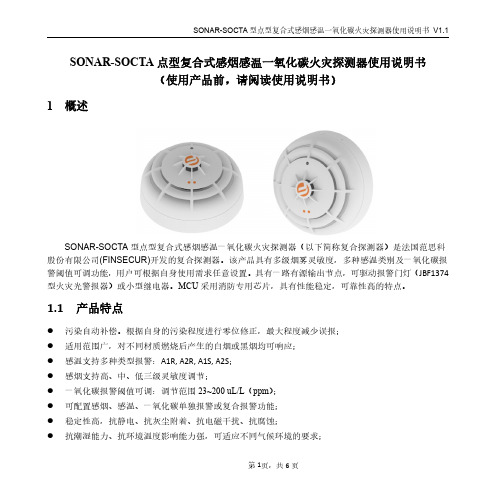
SONAR-SOCTA点型复合式感烟感温一氧化碳火灾探测器使用说明书(使用产品前,请阅读使用说明书)1概述SONAR-SOCTA型点型复合式感烟感温一氧化碳火灾探测器(以下简称复合探测器)是法国范思科股份有限公司(FINSECUR)开发的复合探测器。
该产品具有多级烟雾灵敏度,多种感温类别及一氧化碳报警阈值可调功能,用户可根据自身使用需求任意设置。
具有一路有源输出节点,可驱动报警门灯(JBF1374型火灾光警报器)或小型继电器。
MCU采用消防专用芯片,具有性能稳定,可靠性高的特点。
1.1产品特点●污染自动补偿。
根据自身的污染程度进行零位修正,最大程度减少误报;●适用范围广,对不同材质燃烧后产生的白烟或黑烟均可响应;●感温支持多种类型报警:A1R,A2R,A1S,A2S;●感烟支持高、中、低三级灵敏度调节;●一氧化碳报警阈值可调:调节范围23~200uL/L(ppm);●可配置感烟、感温、一氧化碳单独报警或复合报警功能;●稳定性高,抗静电、抗灰尘附着、抗电磁干扰、抗腐蚀;●抗潮湿能力、抗环境温度影响能力强,可适应不同气候环境的要求;●采用SMT表面贴装工艺,采用导光柱;●内置短路隔离器(电源负极),隔离回路中存在短路故障的线路。
1.2适用范围●复合探测器应用于两总线火灾报警系统中,可配接青鸟消防报警控制器使用;●应用设计遵照国家标准GB50116-2013《火灾自动报警系统设计规范》;●主要用来探测可见的燃烧产物及起火速度缓慢的初期火灾,适用于宾馆客房、办公楼、图书馆、影剧院邮政大楼以及锂离子储能电站等场所。
1.3型号组成2工作原理复合探测器感烟探测部分由迷宫,红外发射部分、红外接收部分及相应的放大处理等电路组成。
正常工作时,当迷宫中没有烟时,红外发射管发出的红外光不能到达接收管,因此,放大器没有输出;而当迷宫中有烟时,红外发光管发出的光由于烟的散色作用,有部分红外光到达接收管,迷宫中烟的浓度越大,放大器输出就越大,当烟浓度达到设定报警阈值时电路给出报警信号。