NXP的flexray收发器芯片TJA1080A
FlexRay-CAN网关在火控系统中的应用

D01:10.19557/ki.l001-9944.2021.03.018FlexRay-CAN网关在糸统中的*用吕孟恩,韩晓明,张鹏军(中北大学机电工程学院,太原030051)摘要:FlexRay总线相比于CAN总线具有高传输速率、高可靠性等优点,是一种正在快速发展的现场总线#目前武器系统控制中使用较为广泛的仍然是CAN总线,因此解决CAN总线与FlexRa y总线之间的数据交互问题可以提高火控系统的信息传输速率$该文以MC9S12XF512微处理器作为核心提出了FlexRay-CAN网关的设计思路,对FlexRay的数据帧进行拆分重组,使其满足CAN协议的数据帧格式,实现两种不同总线之间的数据传输$分析表明FlexRay-CAN网关的实现适用于火炮发射系统,数据传输可靠性得到明显提升$关键词:FlexRay总线;CAN总线;MC9S12XF512微处理器;数据转换中图分类号:TP273.5文献标志码:A文章编号:1001-9944(2021)03-0081-05 Application of FlexRay-Can Bus in Artillery SystemLV Meng-en,HAN Xiao-ming,BHANG Peng-jun(Academy of Mechanical and Electrical Engineering,North University of China,Taiyuan030051,China)Abstract:Compared with CAN bus,FlexRay bus has the advantages of high transmission rate and high reliability.It is a rapidly developing field bus.Currently,CAN bus is still widely used in weapon system control,so solving the problem of data interaction between CAN bus and FlexRay bus can improve the information transmission rate of fire control system.In this paper,with MC9S12XF512microprocessor as the core, the design idea of Flexray-CAN gateway is proposed.The data frame of FlexRay is split and recombined to meet the data frame format of CAN protocol, and the data transmission between two different buses is realized.The analysis shows that the implementation of FlexrayCAN gateway is suitable for artillery firing system, and the reliability of data transmission is obviously improved.Key words:FlexRay bus;CAN bus;MC9S12XF512microprocessor;data conversion目前武器系统通讯仍然多采用CAN总线,随着 对武器系统控制速率及精度要求的不断提高,CAN 总线逐渐显现出不足,如:总线通信速率在系统中某些关键部位无法达到预期要求;传输模式过于简单等。
TJA1080中文资料

3. Quick reference data
Table 1. Symbol VBAT VCC VBUF VIO VTRXD0 VTRXD1 VBP VBM IBAT Quick reference data Parameter supply voltage on pin VBAT supply voltage supply voltage on pin VBUF supply voltage on pin VIO voltage on pin TRXD0 voltage on pin TRXD1 voltage on pin BP voltage on pin BM supply current on pin VBAT low power modes in node configuration normal power modes Conditions no time limit operating range no time limit operating range no time limit operating range no time limit operating range Min −0.3 6.5 −0.3 4.75 −0.3 4.75 −0.3 2.2 −0.3 −0.3 −60 −60 35 0.075 Typ Max +60 60 +5.5 5.25 +5.5 5.25 +5.5 5.25 +5.5 +5.5 +60 +60 50 1 Unit V V V V V V V V V V V V µA mA
TJA1080
FlexRay transceiver
Table 1. Symbol ICC
Quick reference data …continued Parameter supply current Conditions low power modes Normal mode; VBGE = 0 V; VTXEN = VIO; Receive only mode; star Idle mode Normal mode; VBGE = VIO; VTXEN = 0 V; VBUF open Normal mode; VBGE = VIO; VTXEN = 0 V; Rbus = ∞ Ω star Transmit mode star Receive mode
TJA1080ATS2资料

TJA1080ATS/2FlexRay transceiverRev. 04 — 19 February 2009Product data sheet1.General descriptionThe TJA1080A TS/2 is a FlexRay transceiver that is fully compliant with the FlexRayelectrical physical layer specification V2.1 Rev. A (see Ref.1) and partly complies withversion V2.1 Rev. B. It is primarily intended for communication systems from 1Mbit/s to10 Mbit/s, and provides an advanced interface between the protocol controller and thephysical bus in a FlexRay network.The TJA1080A TS/2 can be configured to be used as an active star transceiver or as anode transceiver.The TJA1080A TS/2 provides differential transmit capability to the network and differentialreceive capability to the FlexRay controller.It offers excellent EMC performance as well ashigh ESD protection.The TJA1080A TS/2 actively monitors the system performance using dedicated error andstatus information (readable by any microcontroller), as well as internal voltage andtemperature monitoring.The TJA1080ATS/2supports the mode control as used in NXP Semiconductors TJA1054(see Ref.2) and TJA1041 (see Ref.3) CAN transceivers.The TJA1080A TS/2 is the next step up from the TJA1080 FlexRay transceiver (Ref.4).Being fully pin compatible and offering the same excellent ESD protection, theTJA1080A TS/2 also features:•Improved power-on reset concept•Improved ElectroMagnetic Emission (EME)•Support of 60ns minimum bit time•Improved bus error detection functionalityThis makes the TJA1080ATS/2 an excellent choice in any kind of FlexRay node.See Section14 for a detailed overview of differences between the TJA1080 and theTJA1080A TS/2.2.Features2.1Optimized for time triggered communication systemsI Compliant with FlexRay electrical physical layer specification V2.1 Rev. A (see Ref.1)I Automotive product qualification in accordance with AEC-Q100I Data transfer up to 10 Mbit/sI Support of 60ns minimum bit timeI Very low EME to support unshielded cableI Differential receiver with high common-mode range for ElectroMagnetic Immunity(EMI)I Auto I/O level adaptation to host controller supply voltage V IOI Usable for 14 V and 42 V powered systemsI Bus guardian interface includedI Independent power supply ramp-up for V BA T, V CC and V IOI Transceiver can be used for linear passive bus topologies as well as active startopologies2.2Low power managementI Low power management including two inhibit switchesI Very low current in Sleep and Standby modesI Local and remote wake-upI Supports remote wake-up via dedicated data framesI Wake-up source recognitionI Automatic power-down (in Star-sleep mode) in star configuration2.3Diagnosis (detection and signalling)I Overtemperature detectionI Short-circuit on bus linesI V BA T power-on flag (first battery connection and cold start)I Pin TXEN and pin BGE clampingI Undervoltage detection on pins V BA T, V CC and V IOI Wake source indication2.4ProtectionsI Bus pins protected against 8 kV HBM ESD pulsesI Bus pins protected against transients in automotive environment (ISO7637 class Ccompliant)I Bus pins short-circuit proof to battery voltage (14 V and 42 V) and groundI Fail-safe mode in case of an undervoltage on pins V BA T, V CC or V IOI Passive behavior of bus lines in the event that transceiver is not powered2.5Functional classes according to FlexRay electrical physical layerspecification (see Ref.1)I Bus driver voltage regulator controlI Bus driver - bus guardian control interfaceI Bus driver logic level adaptationI Active star - communication controller interfaceI Active star - bus guardian interfaceI Active star voltage regulator control3.Ordering informationTable 1.Ordering informationType number PackageName Description Version TJA1080A TS/2SSOP20plastic shrink small outline package; 20 leads; body width 5.3 mm SOT339-14.Block diagramFig 1.Block diagramTRXD0V IOV BUFV BA TINH2INH1SIGNAL ROUTERTRANS-MITTERBUS FAILURE DETECTIONNORMAL RECEIVERINPUT VOLTAGE ADAPTATIONOUTPUT VOLTAGE ADAPTATIONSTATE MACHINE015aaa051TJA1080ATS/2V CCV IO BP BMTRXD1TXD RXD RXDINTRXDINTV BATERRN RXENWAKE-UP DETECTIONOSCILLATORUNDERVOLTAGE DETECTIONWAKEOVER-TEMPERATURE DETECTIONLOW-POWER RECEIVERTXEN BGE STBN EN111041920145713181217121516GND68935.Pinning information5.1Pinning5.2Pin descriptionFig 2.Pin configurationTJA1080ATS/2INH2V BUF INH1V CC EN BP V IO BM TXD GND TXEN WAKE RXD V BA T BGE ERRN STBNRXEN TRXD1TRXD0015aaa0521234567891012111413161518172019Table 2.Pin descriptionSymbol PinType DescriptionINH21O inhibit 2 output for switching external voltage regulator INH12O inhibit 1 output for switching external voltage regulator EN 3I enable input; when HIGH enabled; internal pull-down V IO 4P supply voltage for V IO voltage level adaptation TXD 5I transmit data input; internal pull-downTXEN 6I transmitter enable input; when HIGH transmitter disabled; internal pull-upRXD 7O receive data outputBGE 8I bus guardian enable input;when LOW transmitter disabled;internal pull-downSTBN 9I standby input; low-power mode when LOW; internal pull-down TRXD110I/O data bus line 1 for inner star connection TRXD011I/O data bus line 0 for inner star connectionRXEN 12O receive data enable output; when LOW bus activity detected ERRN 13O error diagnoses output; when LOW error detected V BAT 14P battery supply voltageWAKE 15I local wake-up input; internal pull-up or pull-down (depends on voltage at pin WAKE)GND 16P ground BM 17I/O bus line minus BP 18I/O bus line plus V CC 19P supply voltage (+5 V)V BUF20Pbuffer supply voltage6.Functional descriptionThe block diagram of the total transceiver is illustrated in Figure1.6.1Operating configurations6.1.1Node configurationIn node configuration the transceiver operates as a stand-alone transceiver.The transceiver can be configured as node by connecting pins TRXD0 and TRXD1 toground during a power-on situation (PWON flag is set). The configuration will be latchedwhen the PWON flag is reset, see Section6.7.4.The following operating modes are available:•Normal (normal power mode)•Receive-only (normal power mode)•Standby (low power mode)•Go-to-sleep (low power mode)•Sleep (low power mode)6.1.2Star configurationIn star configuration the transceiver operates as a branch of a FlexRay active star.The transceiver can be configured as star by connecting pin TRXD0 or TRXD1 to V BUFduring a PWON situation (PWON flag is set). The configuration will be latched when thePWON flag is reset, see Section 6.7.4 “Power-on flag”.It is possible to redirect data from one branch to other branches via the inner bus.It is alsopossible to send data to all branches via pin TXD,if pins TXEN and BGE have the correctpolarity.The following operating modes are available:•Star-idle (normal power mode)•Star-transmit (normal power mode)•Star-receive (normal power mode)•Star-sleep (low power mode)•Star-standby (low power mode)•Star-locked (normal power mode)In the star configuration all modes are autonomously controlled by the transceiver,exceptin the case of a wake-up.6.1.3Bus activity and idle detectionThe following mechanisms for activity and idle detection are valid for node and star configurations in normal power modes:•If the absolute differential voltage on the bus lines is higher than |V i(dif)det(act)| fort det(act)(bus),then activity is detected on the bus lines and pin RXEN is switched to LOW which results in pin RXD being released:–If,after bus activity detection,the differential voltage on the bus lines is higher than V IH(dif), pin RXD will go HIGH –If, after bus activity detection, the differential voltage on the bus lines is lower than V IL(dif), pin RXD will go LOW•If the absolute differential voltage on the bus lines is lower than |V i(dif)det(act)| fort det(idle)(bus), then idle is detected on the bus lines and pin RXEN is switched to HIGH.This results in pin RXD being blocked (pin RXD is switched to HIGH or stays HIGH)Additionally, in star configuration, activity and idle can be detected (see Figure 6 for state transitions due to activity/idle detection in star configuration):•If pin TXEN is LOW for longer than t det(act)(TXEN), activity is detected on pin TXEN •If pin TXEN is HIGH for longer than t det(idle)(TXEN), idle is detected on pin TXEN •If pin TRXD0 or TRXD1 is LOW for longer than t det(act)(TRXD), activity is detected onpins TRXD0 and TRXD1•If pin TRXD0 and TRXD1 is HIGH for longer than t det(idle)(TRXD), idle is detected onpins TRXD0 and TRXD16.2Operating modes in node configurationThe TJA1080A TS/2 provides two control pins STBN and EN in order to select one of the modes of operation in node configuration.See Table 3for a detailed description of the pin signalling in node configuration, and Figure 3 for the timing diagram.All modes are directly controlled via pins EN and STBN unless an undervoltage situation is present.If V IO and (V BUF or V BA T )are within their operating range,pin ERRN indicates the status of the error flag.[1]Pin ERRN provides a serial interface for retrieving diagnostic information.[2]Valid if V IO and (V BUF or V BA T ) are present.[3]If wake flag is not set.Table 3.Pin signalling in node configurationMode STBN EN ERRN [1]RXEN RXD Transmitter INH1INH2LOWHIGHLOW HIGH LOW HIGHNormal HIGH HIGH error flag seterror flagreset bus activitybus idlebus DA T A_0bus DA T A_1or idle enabled HIGH HIGHReceive-only HIGH LOW disabled Go-to-sleep LOW HIGH error flag set [2]error flagreset wake flag set [2]wakeflagresetwake flag set [2]wake flag resetfloat [3]Standby LOW LOW SleepLOWXfloatfloatThe state diagram in node configuration is illustrated in Figure 5.Fig 3.Timing diagram in Normal mode node configuration001aae439TXDBGERXDBMBP RXENTXENFig 4.Timing diagram of control pins EN and STBN001aag894S2t det(EN)t det(EN)t d(STBN-INH2)t d(STBN-RXD)normalreceive onlystandbyreceive only normalSTBNENERRN0.7V IO0.3V IO0.7V IO0.3V IOThe state transitions are represented with numbers, which correspond with the numbers in column 3 of T able 4 to T able 7.(1)At the first battery connection the transceiver will enter the Standby mode.Fig 5.State diagram in node configuration001aae438NORMAL STBN = HIGH EN = HIGHSTANDBY (1)STBN = LOW EN = LOWSLEEP STBN = LOW EN = XGO-TO-SLEEP STBN = LOW EN = HIGHRECEIVE ONLY STBN = HIGH EN = LOW1412, 229, 1811, 2131, 327, 16, 383, 306, 3310, 2028, 17, 3915, 25, 42, 435192326, 4427, 4536, 3713, 34, 3514, 24, 40, 4128, 29xxxxxxxxxxxxxxxxxxxxx xxxxxxxxxxxxxxxxxxxxxxxxxx xxxxxxx x x x xxxxxxxxxxxxxxxxxxxxxxxxxxxxxx xxxxxxxxxxxxxxxxxxx xx xxxxxxx xxxxxxxxxxxxxxxxxxxxxxxxxxx xxxxxxxxxxxxxxxxxxx xxxxxx xxxxxxxxxxxxxxxxxxxxxxxxxxxxxxxxxxx xxxxxxxxxxxx x xxxxxxxxxxxxxxxxxxxxxx xxxxxxxxxxxxxxxxxxxxxxxxxxxxxx xxxxx xxxxxxxxxxxxxxxxxxxxxxxxxxxxxxxxxxxxxxxxxxxxxxxxxx xxxxxxxx xxxxxxxxxxxxxxxxxxxxxxxxx xxxxxxxxxxxxxxxxxxxx xxxTJA1080A_4© NXP B.V . 2009. All rights reserved.Product data sheet Rev. 04 — 19 February 200910 of 49NXP SemiconductorsTJA1080ATS/2FlexRay transceiver[1]STBN must be set to LOW at least t det(EN) after the falling edge on EN.[2]Positive edge on pin STBN sets the wake flag. In the case of a transition to Normal mode the wake flag is immediately cleared.[3]Setting the wake flag clears the UV VIO , UV VBA T and UV VCC flags.[4]Hold time of go-to-sleep is less than t h(gotosleep).[5]Hold time of go-to-sleep becomes greater than t h(gotosleep).Table 4.State transitions forced by EN and STBN (node configuration)→ indicates the action that initiates a transaction;→1 and →2 are the consequences of a transaction.Transition from mode Direction to modeTransition numberPin Flag NoteSTBN EN UV VIO UV VBAT UV VCC PWON Wake NormalReceive-only 1H → L cleared cleared cleared cleared cleared Go-to-sleep 2→ LH cleared cleared cleared cleared cleared Standby3→ L→ L cleared cleared cleared cleared cleared [1]Receive-only Normal4H→ H cleared cleared cleared X X Go-to-sleep 5→ L → H cleared cleared cleared X X Standby6→ L L cleared cleared cleared X XStandbyNormal 7→ H → H cleared cleared 2→ cleared X 1→ cleared [2][3]Receive-only 8→ H L cleared cleared 2→ cleared X 1→ set [2][3]Go-to-sleep9L → H cleared cleared X X XGo-to-sleepNormal 10→ H H cleared cleared cleared X 1→ cleared [2][4]Receive-only 11→ H → L cleared cleared cleared X 1→ set [2][4]Standby 12L → L cleared cleared X X X [4]Sleep13L H cleared cleared XX cleared [5]SleepNormal14→H H 2→ cleared 2→ cleared 2→ cleared X 1→ cleared [2][3]Receive-only 15→HL2→ cleared2→ cleared2→ clearedX1→ set[2][3]元器件交易网© NXP B.V . 2009. All rights reserved.Rev. 04 — 19 February 200911 of 49TJA1080ATS/2FlexRay transceiver[1]Setting the wake flag clears the UV VIO , UV VBA T and UV VCC flag.[2]Transition via Standby mode.Go-to-sleepNormal 20H H cleared cleared 1→ cleared X → set [1]Receive-only 21H L cleared cleared 1→ cleared X → set [1]Standby 22L L cleared cleared 1→ cleared X → set [1]Go-to-sleep23L H cleared cleared 1→ cleared X → set [1]SleepNormal 24H H 1→ cleared 1→ cleared 1→ cleared X → set [1][2]Receive-only 25H L 1→ cleared 1→ cleared 1→ cleared X → set [1][2]Standby 26L L 1→ cleared 1→ cleared 1→ cleared X → set [1]Go-to-sleep27LH1→ cleared1→ cleared1→ clearedX→ set[1][2]© NXP B.V . 2009. All rights reserved.Rev. 04 — 19 February 200912 of 49TJA1080ATS/2FlexRay transceiver[1]UV VIO , UV VBA T or UV VCC detected clears the wake flag.[2]UV VIO overrules UV VCC .[3]UV VBA T overrules UV VCC .Sleep 32cleared → set cleared X 1→ cleared [1]Standby33cleared cleared → set X 1→ cleared [1]Go-to-sleep Sleep 34→ set cleared cleared X 1→ cleared [1]Sleep 35cleared → set cleared X 1→ cleared [1]StandbySleep 36→ set cleared X X 1→ cleared [1][2]Sleep37cleared→ setXX1→ cleared[1][3]© NXP B.V . 2009. All rights reserved.Rev. 04 — 19 February 200913 of 49TJA1080ATS/2FlexRay transceiver[1]Recovery of UV VCC flag.[2]Recovery of UV VBAT flag.[3]Clearing the UV VBAT flag sets the wake flag. In the case of a transition to Normal mode the wake flag is immediately cleared.[4]Recovery of UV VIO flag.Receive-only 42H L cleared → cleared cleared X 1→ set [2][3]Receive-only 43H L → cleared cleared cleared X X [4]Standby 44L L cleared → cleared cleared X 1→ set [2][3]Sleep 45L X → cleared cleared cleared X cleared [4]Go-to-sleep 46L H cleared → cleared cleared X 1→ set [2][3]Sleep47LX→ clearedclearedclearedXcleared[4]FlexRay transceiver6.2.1Normal modeIn Normal mode the transceiver is able to transmit and receive data via the bus lines BP and BM. The output of the normal receiver is directly connected to pin RXD.The transmitter behavior in Normal mode of operation, with no time-out present on pinsTXEN and BGE and the temperature flag not set, is given in Table8.In this mode pins INH1 and INH2 are set HIGH.Table 8.Transmitter function tableBGE TXEN TXD TransmitterL X X transmitter is disabledX H X transmitter is disabledH L H transmitter is enabled; the bus lines are actively driven; BP is drivenHIGH and BM is driven LOWH L L transmitter is enabled; the bus lines are actively driven; BP is drivenLOW and BM is driven HIGH6.2.2Receive-only modeIn Receive-only mode the transceiver can only receive data. The transmitter is disabled, regardless of the voltages on pins BGE and TXEN.In this mode pins INH1 and INH2 are set HIGH.6.2.3Standby modeIn Standby mode the transceiver has entered a low power mode which means very lowcurrent consumption. In the Standby mode the device is not able to transmit or receivedata and the low power receiver is activated to monitor for bus wake-up patterns.Standby mode can be entered if the correct polarity is applied to pins EN and STBN (see Figure5 and T able4) or an undervoltage is present on pin V CC; see Figure5.In this mode, pin INH1 is set HIGH.If the wake flag is set, pin INH2 is set to HIGH and pins RXEN and RXD are set to LOW, otherwise pin INH2 is floating and pins RXEN and RXD are set to HIGH; see Section6.5.6.2.4Go-to-sleep modeIn this mode the transceiver behaves as in Standby mode. If this mode is selected for alonger time than the go-to-sleep hold time parameter (minimum hold time) and the wake flag has been previously cleared, the transceiver will enter Sleep mode, regardless of the voltage on pin EN.FlexRay transceiver6.2.5Sleep modeIn Sleep mode the transceiver has entered a low power mode. The only difference with Standby mode is that pin INH1is also set floating.Sleep mode is also entered if the UV VIO or UV VBA T flag is set.In case of an undervoltage on pin V CC or V BAT while V IO is present,the wake flag is set by a positive edge on pin STBN.The undervoltage flags will be reset by setting the wake flag,and therefore the transceiver will enter the mode indicated on pins EN and STBN if V IO is present.A detailed description of the wake-up mechanism is given in Section 6.5.6.3Operating modes in star configurationIn star configuration mode control via pins EN and STBN is not possible. The transceiver autonomously controls the operating modes except in the case of wake-up.The timing diagram of a transceiver configured in star configuration is illustrated in Figure 7. The state diagram in star configuration is illustrated in Figure 6. A detailed description of the pin signalling in star configuration is given in Table 9.If V IO and (V BUF or V BA T )are within their operating range,pin ERRN will indicate the error flag.[1]Pin ERRN provides a serial interface for retrieving diagnostic information.[2]TRXD lines switched as output if TXEN activity is the initiator for Star-transmit mode.[3]TRXD lines are switched as input if TRXD activity is the initiator for Star-transmit mode.[4]Valid if V IO and (V BUF or V BA T ) are present.Pin BGE must be HIGH in order to enable the transmitter via pin TXEN. If pin BGE isLOW,it is not possible to activate the transmitter via pin TXEN.If pin TXEN is not used (no controller connected to the transceiver), it has to be connected to pin GND in order to prevent TXEN activity detection.In all normal modes pin RXD is connected to the output of the normal mode receiver and therefore represents the data on the bus lines.Table 9.Pin signalling in star configurationModeTRXD0 /TRXD1ERRN [1]RXEN RXD Transmitter INH1INH2LOWHIGHLOWHIGH LOW HIGH Star-transmit output [2]input [3]error flag set error flag reset bus activitybus idlebus DA TA_0bus DA T A_1or idleenabled HIGHHIGHStar-receive output disabledStar-idle input Star-locked input Star-standby input error flag set [4]error flag reset wake flag set [4]wake flag reset wake flag set [4]wake flagreset Star-sleepinputfloat floatFlexRay transceiver(1)At the first battery connection the transceiver will enter the Star-standby mode. Fig 6.State diagram in star configuration 001aae441STAR TRANSMIT INH1 = HIGHINH2 = HIGHSTAR IDLEINH1 = HIGHINH2 = HIGHSTAR LOCKEDINH1 = HIGHINH2 = HIGHSTAR SLEEPINH1 = floatingINH2 = floatingidle detected onTRXD0, TRXD1,TXEN and thebus linesTRXD0, TRXD1,TXEN activity detectedSTAR RECEIVEINH1 = HIGHINH2 = HIGHSTAR STANDBY(1)INH1 = HIGHINH2 = HIGHidle detected onTRXD0, TRXD1,TXEN and thebus linesidle detected onthe bus linesand TXEN for longerthan t to(locked-idle)TXEN activity detected for longer than t to(tx-locked)bus activity detected forlonger than t to(rx-locked)bus activitydetectedwakeflag 1wake flag 1 orUV VCC signal 0no acivity on TRXD0,TRXD1, TXEN and thebus lines for longerthan t to(idle-sleep)from any mode if UV VCCflag is set regardless PWON flag from star idle, star transmit or star receive if wake flag set and under voltage present on V CC for longer thant > t to(uv)(VCC)time in starlocked longer than t to(locked-sleep)FlexRay transceiver6.3.1Star-idle modeThis mode is entered if one of the following events occurs:•From Star-receive mode and Star-transmit mode if idle is detected on the bus lines,onpin TXEN and on pins TRXD0 and TRXD1.•If the transceiver is in Star-locked mode and idle is detected on the bus lines and pinTXEN for longer than t to(locked-idle).•If the transceiver is in Star-standby mode and the wake flag is set or no undervoltageis present.•If the transceiver is in Star-sleep mode and the wake flag is set,the transceiver entersStar-idle mode in order to obtain a stable starting point (no glitches on the bus lines etc.).In Star-idle mode the transceiver monitors pins TXEN, TRXD0 and TRXD1 and the bus lines for activity. In this mode the transmitter is disabled.TRXDOUT is a virtual signal that indicates the state of the TRXD lines. TRXDOUT HIGH means TRXD lines switched as output. TRXDOUT LOW means TRXD lines switched as input.Fig 7.Timing diagram in star configuration001aae440TXENTXDRXDBMBP TRXD1TRXD0star transmitstar idle star idle star idlestar receive star transmit RXENTRXDOUTFlexRay transceiver6.3.2Star-transmit modeThis mode is entered if one of the following events occur:•If the transceiver is in Star-idle mode and activity is detected on pin TXEN.•If the transceiver is in Star-idle mode and activity is detected on pins TRXD0 and TRXD1.In Star-transmit mode the transmitter is enabled and the transceiver can transmit data on the bus lines and on the TRXD lines.It transmits the data received on pins TXD or TRXD0 and TRXD1, depending on where activity is detected:•If activity is detected on the TRXD lines, the transceiver transmits data from pins TRXD0 and TRXD1 to the bus.•If activity is detected on the TXEN,the transceiver transmits data from pin TXD to the bus and to the TRXD lines.6.3.3Star-receive modeThis mode is entered if the transceiver is in Star-idle mode and activity has been detected on the bus lines.In Star-receive mode the transceiver transmits data received on the bus via the TRXD0and TRXD1 lines to other transceivers connected to the TRXD lines. The transmitter isalways disabled.RXD,which represents the data on the bus lines,is output at TRXD0and TRXD1.6.3.4Star-standby modeThis mode is entered if one of the following events occur:•From Star-idle, Star-transmit or Star-receive modes if the wake flag is set and an undervoltage on pin V CC is present for longer than t to(uv)(VCC).•If the PWON flag is set.In Star-standby mode the transceiver has entered a low power mode. In this mode thecurrent consumption is as low as possible to prevent discharging the capacitor at pinV BUF.If pins V IO and V BUF are within their operating range,pins RXD and RXEN will indicate the wake flag.FlexRay transceiver6.3.5Star-sleep modeThis mode is entered if one of the following events occur:•From any mode if an undervoltage on pin V CC is present for longer than t det(uv)(VCC).•If the transceiver is in Star-idle mode and no activity is detected on the bus lines and pins TXEN, TRXD0 and TRXD1 for longer than t to(idle-sleep).•If Star-locked mode is active for longer than t to(locked-sleep).In Star-sleep mode the transceiver has entered a low power mode. In this mode thecurrent consumption is as low as possible to prevent the car battery from discharging.The inhibit switches are switched off.In this mode the wake flag wakes the transceiver. A detailed description of the wake-upmechanism is given in Section6.5.If pins V IO and V BUF are within their operating range,pins RXD and RXEN will indicate the wake flag.6.3.6Star-locked modeThis mode is entered if one of the following events occur:•If the transceiver is in Star-transmit mode and activity on pin TXEN is detected for longer than t to(tx-locked).•If the transceiver is in Star-receive mode and activity is detected on the bus lines for longer than t to(rx-locked).This mode is a fail-silent mode and in this mode the transmitter is disabled.6.4Start-upThe TJA1080ATS/2initialization is independent of the way the voltage supplies V BAT,V CC and V IO ramp up. A dedicated power-up sequence is not necessary.6.4.1Node configurationNode configuration can be selected by applying a voltage lower than 0.3V BUF to pinsTRXD0 and TRXD1 during power-on. Node configuration is latched by resetting thePWON flag while the voltage on pins TRXD0 and TRXD1 is lower than 0.3V BUF; seeSection6.7.4 for (re)setting the PWON flag.6.4.2Star configurationStar configuration can be selected by applying a voltage higher than 0.7V BUF to pinsTRXD0 or TRXD1 during power-on. Star configuration is latched by resetting the PWON flag while one of the voltages on pins TRXD0 or TRXD1 is higher than 0.7V BUF. SeeSection6.7.4 for (re)setting the PWON flag. In this case the transceiver goes fromStar-standby mode to Star-idle mode.FlexRay transceiver6.5Wake-up mechanism6.5.1Node configurationIn Sleep mode (pins INH1 and INH2 are switched off), the transceiver will enter Standbymode or Go-to-sleep mode (depending on the value at pin EN), if the wake flag is set.Consequently, pins INH1 and INH2 are switched on.If no undervoltage is present on pins V IO and V BA T, the transceiver switches immediatelyto the mode indicated on pins EN and STBN.In Standby, Go-to-sleep and Sleep modes pins RXD and RXEN are driven LOW if thewake flag is set.6.5.2Star configurationIn Star-sleep mode (pins INH1 and INH2 are switched off), the transceiver will enterStar-idle mode(pins INH1and INH2are switched on)if the wakeflag is set.After entering Star-idle mode the transceiver monitors for activity to choose the appropriate modetransition (see Figure6).6.5.3Remote wake-up6.5.3.1Bus wake-up via wake-up patternBus wake-up is detected if two consecutive DATA_0of at least t det(wake)DATA_0separated by an idle or DA T A_1 of at least t det(wake)idle, followed by an idle or DA TA_1 of at leastt det(wake)idle are present on the bus lines within t det(wake)tot.t det(wake)tot0 VV dif−425 mVt det(wake)Data_0t det(wake)idle t det(wake)Data_0t det(wake)idle001aae442 Fig 8.Bus wake-up timing6.5.3.2Bus wake-up via dedicated FlexRay data frameThe reception of a dedicated data frame, emulating a valid wake-up pattern, as shown inFigure9, sets the wake-up flag of the TJA1080ATS/2.Due to the Byte Start Sequence (BSS), preceding each byte, the DATA_0 and DA TA_1phases for the wake-up symbol are interrupted every 1µs. For 10Mbit/s the maximuminterruption time is 130ns. Such interruptions do not prevent the transceiver fromrecognizing the wake-up pattern in the payload of a data frame.The wake-up flag will not be set upon reception of an invalid wake-up pattern.。
汽车控制系统效能升级!FlexRay网络标准详解
汽车控制系统效能升级!FlexRay网络标准详解自2003年组建以来,AUTOSAR(汽车开放系统架构)联盟一直致力于改变车载网络和电子控制单元(ECU)的设计方式。
AUTOSAR提出了一个符合业界标准的车载网络设计方法,使行业能够集成、交换和传输汽车网络内的功能、数据和信息。
这一标准极大地促进了汽车原始设备制造商(OEM)及其一级供应商之间的合作,使他们能够以一种一致、明确且机器可读的格式来交换设计信息。
一辆汽车的不同部分对安全及性能有不同要求,而支持它们的车载网络必须具备可预测的安全性能。
随着汽车技术的不断演变,人们已经可以用一系列总线技术来连接豪华汽车上最多100个不同的ECU,这些总线技术通常包括LIN、CAN、FlexRay、MOST和基于以太网的架构。
如果靠手动来管理这些ECU 之间数以千计的信息和交互操作是不可能的,因此汽车设计人员必然用自动化设计和合成工具来预测网络性能和调整车载功能。
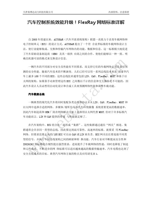
汽车数据总线一辆典型的现代化汽车将同时装配各类总线和协议并从LIN、CAN、FlexRay、MOST和以太网中选择合适的网络。
多媒体/视听信号和汽车环绕摄像系统需要更高的数据速率,因此汽车制造商和OEM厂商在网络解决方案上选择用以太网代替MOST.但对于许多标准汽车功能而言,LIN和CAN提供的带宽与性能就足够了。
在汽车架构中,ECU组合在一起形成“集群”,这些集群通过通信“网关”相连。
集群通常会共享同一类型的总线,因此要达到高可靠性、高速率的标准,就要采用FlexRay 网络,但要求没那么高的门锁ECU可以由CAN或LIN来负责。
ECU网关往往要连接不同类型的信号,并执行不同总线架构之间的映射和转换功能。
汽车行业对不断提高安全性和ISO26262等标准的合规性提出强烈需求,进而提升了车载网络的性能,同时也降低了制造和元件成本。
不断进步的网络标准可以适应越来越高的数据传输速率,汽车电缆也达到了安全且低成本的目标。
两后轮驱动的电动汽车的差速控制

武汉理工大学
硕士学位论文
两后轮驱动的电动汽车的差速控制
姓名:马建国
申请学位级别:硕士
专业:电路与系统
指导教师:黄涛
20070401
第3章电子差速控制算法的选择
3.1自然差速的可行性分析
当车辆行驶在转弯路面或巷道时,为了防止不稳定的驱动,内轮和外轮将具有不同的速度。
传统的内燃机车辆通过一个带减速装置的机械差速器来实现这一功能“”,如图3-1所示。
本研究的电动汽车采用独立的轮式驱动方式,即每个车轮有一个直接驱动的电机。
这样,与单电机驱动的电动汽车相比,本研究所要设计的样车,其两个后轮都能独立提供驱动力,可以按运行工况需求独立分配功率,因此不需要传统的机械差速器,而代之为新技术内涵的电子差速系统。
图3-1传统机械差速器
根据汽车行驶运动学,以及实际的车轮、道路及它们之间的相互关系可以知道:汽车在行驶过程中,左右车轮在同一时间内所滚过的行程往往是不相等的。
例如,汽车在转弯时,为满足运动学的要求,汽车外侧车轮的行程始终长于内侧的行程。
此外,即使汽车直线行驶,也会由于左右车轮在同一时间内所滚过的路面情况的不同,或由于左右车轮轮胎气压、轮胎负荷、胎面磨损程度的不同,以及制造误差引起左右车轮外径不等或滚动半径不等,而导致车轮行
31。
基于TJA1080的FlexRay节点驱动电路设计

( 装 甲兵 工 程 学 院控 制 工 程 系 , 北京 1 0 0 0 7 2 )
摘要 : F l e x R a y总线 作 为 新 一 代 车 内控 制 总 线 具 有 很 好 的实 时 性 与 可 靠 性 。分 析 了 F l e x R a y总 线 的 特 点 , 以 T MS 3 2 0 F 2 8 3 3 5 、 M F R 4 3 1 0与 T J A1 0 8 0建立 了 F l e x R a y节点 , 针对 当前 电子通信 系统 的电磁兼容 ( E MC ) 问题 , 提 出了 在 F l e x R a y节点驱动 电路 中加入数字 隔离器 、 共模扼 流圈、 分离端接 的方法 , 提高了整个 F l e x R a y 节点的 E MC性能 。
F l e x Ra y No d e Dr i v e Ci r c u i t De s i g n Ba s e d o n TJ A1 0 8 0 L I A O Z i — l i , G A O Q i a n g ,Y U A N D o n g
Abs t r ac t :F l e x Ra y b u s h a s a b e t t e r r e a l t i me p e fo r r ma n c e a n d a b e t t e r r e l i a b i l i t y a s a n e w c o n t r o l b us i n 。 s i d e t h e v e h i c l e . Af te r t h e a n a l y s i s o f Fl e x Ra y b us ,t h i s pa p e r a i me d t o s o l v e t h e p r o b l e m o f EMC o f e l e c -
FlexRay总线在电力系统继电保护装置中的应用_牛志刚

第38卷第16期电力系统保护与控制Vol.38 No.16 2010年8月16日Power System Protection and Control Aug. 16, 2010 FlexRay总线在电力系统继电保护装置中的应用牛志刚1,肖 昆1,王建林2,李 黔3,刘 睿3,梁 荧3(1.上海电力学院电力与自动化工程学院,上海 200090;2.艾木恩电力科技(上海)有限公司,上海 200090;3.四川省电力工业调整试验所,四川 成都 610016)摘要:在电力系统继电保护装置内部,采用FlexRay作为背板总线解决方案,构建网络化硬件平台,装置内的各模块作为FlexRay节点通过总线方式互连通信。
根据保护装置内节点的不同功能需要,提出了FlexRay通信节点的三种实现方案,并讨论了FlexRay通信节点软硬件设计中的若干技术要点。
以FlexRay总线构建的网络化硬件平台易于扩展,可以优化继电保护装置硬件结构,并有利于实现IEC61850标准下IED硬件结构的标准化和通用化。
关键词:FlexRay;继电保护;背板总线;硬件平台Application of FlexRay in protective relay unit of electric power systemNIU Zhi-gang 1,XIAO Kun1,WANG Jian-lin 2,LI Qian3,LIU Rui3,LIANG Ying3(1. School of Power and Automation Engineering, Shanghai Institute of Electric Power,Shanghai 200090,China;2. M&N Electric Power Technology (Shanghai) CO.,Ltd,Shanghai 200090,China;3. Sichuan Electric Power Commission and Test Institute,Chengdu 610016,China)Abstract:FlexRay is adopted as internal backboard bus solution for protective relay unit to construct a networking hardware platform in electric power system.Different modules in the unit can communicate with each other through the bus as FlexRay nodes.Three schemes are proposed for constructing a FlexRay node according to the different needs of its function,and some key technical points in the software and hardware design are discussed.The FlexRay-based networking hardware platform has flexible expansibility, can optimize the architecture of protective relay and avail to implement the standardization and generalization of hardware architecture of IEC61850-based IED.Key words:FlexRay;protective relay;backboard bus;hardware platform中图分类号: TM774 文献标识码:A 文章编号: 1674-3415(2010)16-0073-050 引言电力系统的继电保护装置是典型的实时控制系统。
Flexray收发器TJA1080A的规格

TJA1080AFlexRay transceiverRev. 02 — 26 August 2008Preliminary data sheet1.General descriptionThe TJA1080A is a FlexRay transceiver, which is in line with the FlexRay electricalphysical layer specification V2.1 Rev. A (see Ref.1). It is primarily intended forcommunication systems from 1Mbit/s to 10 Mbit/s, and provides an advanced interfacebetween the protocol controller and the physical bus in a FlexRay network.The TJA1080A can be configured to be used as an active star transceiver or as a nodetransceiver.The TJA1080A provides differential transmit capability to the network and differentialreceive capability to the FlexRay controller.It offers excellent EMC performance as well ashigh ESD protection.The TJA1080A actively monitors the system performance using dedicated error andstatus information (readable by any microcontroller), as well as internal voltage andtemperature monitoring.The TJA1080A supports the mode control as used in NXP Semiconductors TJA1054(see Ref.2) and TJA1041 (see Ref.3) CAN transceivers.The TJA1080A is the next step up from the TJA1080 FlexRay transceiver (Ref.4). Beingfully pin compatible and offering the same excellent ESD protection, the TJA1080A alsofeatures:•Improved power-on reset concept•Improved ElectroMagnetic Emission (EME)•Support of 70ns minimum bit time•Improved bus error detection functionalityThis makes the TJA1080A an excellent choice in any kind of FlexRay nodes.See Section14 for a detailed overview of differences between the TJA1080 and theTJA1080A.2.Features2.1Optimized for time triggered communication systemsI Compliant with FlexRay electrical physical layer specification V2.1 Rev. A (see Ref.1)I Automotive product qualification in accordance with AEC-Q100I Data transfer up to 10 Mbit/sI Support of 70ns minimum bit timeI Very low EME to support unshielded cableI Differential receiver with high common-mode range for ElectroMagnetic Immunity(EMI)I Auto I/O level adaptation to host controller supply voltage V IOI Usable for 14 V and 42 V powered systemsI Bus guardian interface includedI Independent power supply ramp-up for V BA T, V CC and V IOI Transceiver can be used for linear passive bus topologies as well as active startopologies2.2Low power managementI Low power management including two inhibit switchesI Very low current in Sleep and Standby modeI Wake-up via wake-up symbol or dedicated FlexRay data frames on the bus lines(remote),negative edge on pin WAKE(local),and a positive edge on pin STBN if V IO is presentI Wake-up source recognitionI Automatic power-down (in Star-sleep mode) in star configuration2.3Diagnosis (detection and signalling)I Overtemperature detectionI Short-circuit on bus linesI V BA T power-on flag (first battery connection and cold start)I Pin TXEN and pin BGE clampingI Undervoltage detection on pins V BA T, V CC and V IOI Wake source indication2.4ProtectionsI Bus pins protected against 8 kV HBM ESD pulsesI Bus pins protected against transients in automotive environment (ISO7637 class Ccompliant)I Bus pins short-circuit proof to battery voltage (14 V and 42 V) and groundI Fail-safe mode in case of an undervoltage on pins V BA T, V CC or V IOI Passive behavior of bus lines in the event that transceiver is not powered2.5Functional classes according to FlexRay electrical physical layerspecification (see Ref.1)I Bus driver voltage regulator controlI Bus driver - bus guardian control interfaceI Bus driver logic level adaptionI Active star - communication controller interfaceI Active star - bus guardian interfaceI Active star voltage regulator control3.Ordering informationTable 1.Ordering informationType number PackageName Description Version TJA1080A TS/1SSOP20plastic shrink small outline package; 20 leads; body width 5.3 mm SOT339-14.Block diagramFig 1.Block diagramTRXD0V IOV BUFV BA TINH2INH1SIGNAL ROUTERTRANS-MITTERBUS FAILURE DETECTIONNORMAL RECEIVERINPUT VOLTAGE ADAPTATIONOUTPUT VOLTAGE ADAPTATIONSTATE MACHINE001aag892TJA1080AV CCV IO BP BMTRXD1TXD RXD RXDINTRXDINTV BATERRN RXENWAKE-UP DETECTIONOSCILLATORUNDERVOLTAGE DETECTIONWAKEOVER-TEMPERATURE DETECTIONLOW-POWER RECEIVERTXEN BGE STBN EN111041920145713181217121516GND68935.Pinning information5.1Pinning5.2Pin descriptionFig 2.Pin configurationTJA1080ATSINH2V BUF INH1V CC EN BP V IO BM TXD GND TXEN WAKE RXD V BA T BGE ERRN STBNRXEN TRXD1TRXD0001aag8931234567891012111413161518172019Table 2.Pin descriptionSymbol PinType DescriptionINH21O inhibit 2 output for switching external voltage regulator INH12O inhibit 1 output for switching external voltage regulator EN 3I enable input; when HIGH enabled; internal pull-down V IO 4P supply voltage for V IO voltage level adaptation TXD 5I transmit data input; internal pull-downTXEN 6I transmitter enable input; when HIGH transmitter disabled; internal pull-upRXD 7O receive data outputBGE 8I bus guardian enable input;when LOW transmitter disabled;internal pull-downSTBN 9I standby input; low-power mode when LOW; internal pull-down TRXD110I/O data bus line 1 for inner star connection TRXD011I/O data bus line 0 for inner star connectionRXEN 12O receive data enable output; when LOW bus activity detected ERRN 13O error diagnoses output; when LOW error detected V BAT 14P battery supply voltageWAKE 15I local wake-up input; internal pull-up or pull-down (depends on voltage at pin WAKE)GND 16P ground BM 17I/O bus line minus BP 18I/O bus line plus V CC 19P supply voltage (+5 V)V BUF20Pbuffer supply voltage6.Functional descriptionThe block diagram of the total transceiver is illustrated in Figure1.6.1Operating configurations6.1.1Node configurationIn node configuration the transceiver operates as a stand-alone transceiver.The transceiver can be configured as node by connecting pins TRXD0 and TRXD1 toground during a power-on situation (PWON flag is set). The configuration will be latchedwhen the PWON flag is reset, see Section6.7.4.The following operating modes are available:•Normal (normal power mode)•Receive-only (normal power mode)•Standby (low power mode)•Go-to-sleep (low power mode)•Sleep (low power mode)6.1.2Star configurationIn star configuration the transceiver operates as a branch of a FlexRay active star.The transceiver can be configured as star by connecting pin TRXD0 or TRXD1 to V BUFduring a PWON situation (PWON flag is set). The configuration will be latched when thePWON flag is reset, see Section 6.7.4 “Power-on flag”.It is possible to redirect data from one branch to other branches via the inner bus.It is alsopossible to send data to all branches via pin TXD,if pins TXEN and BGE have the correctpolarity.The following operating modes are available:•Star-idle (normal power mode)•Star-transmit (normal power mode)•Star-receive (normal power mode)•Star-sleep (low power mode)•Star-standby (low power mode)•Star-locked (normal power mode)In the star configuration all modes are autonomously controlled by the transceiver,exceptin the case of a wake-up.6.1.3Bus activity and idle detectionThe following mechanisms for activity and idle detection are valid for node and star configurations in normal power modes:•If the absolute differential voltage on the bus lines is higher than |V i(dif)det(act)| fort det(act)(bus),then activity is detected on the bus lines and pin RXEN is switched to LOW which results in pin RXD being released:–If,after bus activity detection,the differential voltage on the bus lines is higher than V IH(dif), pin RXD will go HIGH –If, after bus activity detection, the differential voltage on the bus lines is lower than V IL(dif), pin RXD will go LOW•If the absolute differential voltage on the bus lines is lower than |V i(dif)det(act)| fort det(idle)(bus), then idle is detected on the bus lines and pin RXEN is switched to HIGH.This results in pin RXD being blocked (pin RXD is switched to HIGH or stays HIGH)Additionally, in star configuration, activity and idle can be detected (see Figure 6 for state transitions due to activity/idle detection in star configuration):•If pin TXEN is LOW for longer than t det(act)(TXEN), activity is detected on pin TXEN •If pin TXEN is HIGH for longer than t det(idle)(TXEN), idle is detected on pin TXEN •If pin TRXD0 or TRXD1 is LOW for longer than t det(act)(TRXD), activity is detected onpins TRXD0 and TRXD1•If pin TRXD0 and TRXD1 is HIGH for longer than t det(idle)(TRXD), idle is detected onpins TRXD0 and TRXD16.2Operating modes in node configurationThe TJA1080A provides two control pins STBN and EN in order to select one of themodes of operation in node configuration.See Table 3for a detailed description of the pin signalling in node configuration, and Figure 3 for the timing diagram.All modes are directly controlled via pins EN and STBN unless an undervoltage situation is present.If V IO and (V BUF or V BA T )are within their operating range,pin ERRN indicates the status of the error flag.[1]Pin ERRN provides a serial interface for retrieving diagnostic information.[2]Valid if V IO and (V BUF or V BA T ) are present.[3]If wake flag is not set.Table 3.Pin signalling in node configurationMode STBN EN ERRN [1]RXEN RXD Transmitter INH1INH2LOWHIGHLOW HIGH LOW HIGHNormal HIGH HIGH error flag seterror flagreset bus activitybus idlebus DA T A_0bus DA T A_1or idle enabled HIGH HIGHReceive-only HIGH LOW disabled Go-to-sleep LOW HIGH error flag set [2]error flagreset wake flag set [2]wakeflagresetwake flag set [2]wake flag resetfloat [3]Standby LOW LOW SleepLOWXfloatfloatThe state diagram in node configuration is illustrated in Figure 5.Fig 3.Timing diagram in Normal mode node configuration001aae439TXDBGERXDBMBP RXENTXENFig 4.Timing diagram of control pins EN and STBN001aag894S2t det(EN)t det(EN)t d(STBN-INH2)t d(STBN-RXD)normalreceive onlystandbyreceive only normalSTBNENERRN0.7V IO0.3V IO0.7V IO0.3V IOThe state transitions are represented with numbers, which correspond with the numbers in column 3 of T able 4 to T able 7.(1)At the first battery connection the transceiver will enter the Standby mode.Fig 5.State diagram in node configuration001aae438NORMAL STBN = HIGH EN = HIGHSTANDBY (1)STBN = LOW EN = LOWSLEEP STBN = LOW EN = XGO-TO-SLEEP STBN = LOW EN = HIGHRECEIVE ONLY STBN = HIGH EN = LOW1412, 229, 1811, 2131, 327, 16, 383, 306, 3310, 2028, 17, 3915, 25, 42, 435192326, 4427, 4536, 3713, 34, 3514, 24, 40, 4128, 29xxxxxxxxxxxxxxxxxxxxx xxxxxxxxxxxxxxxxxxxxxxxxxx xxxxxxx x x x xxxxxxxxxxxxxxxxxxxxxxxxxxxxxx xxxxxxxxxxxxxxxxxxx xx xx xxxxx xxxxxxxxxxxxxxxxxxxxxxxxxxx xxxxxxxxxxxxxxxxxxx xxxxxx xxxxxxxxxxxxxxxxxxxxxxxxxxxxxxxxxxx xxxxxxxxxxxx x xxxxxxxxxxxxxxxxxxxxxx xxxxxxxxxxxxxxxxxxxxxxxxxxxxxx xxxxx xxxxxxxxxxxxxxxxxxxxxxxxxxxxxxxxxxxxxxxxxxxxxxxxxx xxxxxxxx xxxxxxxxxxxxxxxxxxxxxxxxx xxxxxxxxxxxxxxxxxxxx xxxTJA1080A_2© NXP B.V . 2008. All rights reserved.Preliminary data sheet Rev. 02 — 26 August 200810 of 50NXP SemiconductorsTJA1080AFlexRay transceiver[1]STBN must be set to LOW at least t det(EN) after the falling edge on EN.[2]Positive edge on pin STBN sets the wake flag. In the case of a transition to Normal mode the wake flag is immediately cleared.[3]Setting the wake flag clears the UV VIO , UV VBA T and UV VCC flag.[4]Hold time of go-to-sleep is less than the minimum hold time.[5]Hold time of go-to-sleep becomes greater than the minimum hold time.Table 4.State transitions forced by EN and STBN (node configuration)→ indicates the action that initiates a transaction;→1 and →2 are the consequences of a transaction.Transition from mode Direction to modeTransition numberPin Flag NoteSTBN EN UV VIO UV VBAT UV VCC PWON Wake NormalReceive-only 1H → L cleared cleared cleared cleared cleared Go-to-sleep 2→ L H cleared cleared cleared cleared cleared Standby3→ L → L cleared cleared cleared cleared cleared [1]Receive-only Normal4H → H cleared cleared cleared X X Go-to-sleep 5→ L → H cleared cleared cleared X X Standby6→ L L cleared cleared cleared X XStandbyNormal 7→ H → H cleared cleared 2→ cleared X 1→ cleared [2][3]Receive-only 8→ H L cleared cleared 2→ cleared X 1→ set [2][3]Go-to-sleep9L → H cleared cleared X X XGo-to-sleepNormal 10→ H H cleared cleared cleared X 1→ cleared [2][4]Receive-only 11→ H → L cleared cleared cleared X 1→ set [2][4]Standby 12L → L cleared cleared X X X [4]Sleep13LH cleared cleared XX cleared [5]SleepNormal14→ H H 2→ cleared 2→ cleared 2→ cleared X 1→ cleared [2][3]Receive-only 15→ HL2→ cleared2→ cleared2→ clearedX1→ set[2][3]TJA1080A_2© NXP B.V . 2008. All rights reserved.Preliminary data sheet Rev. 02 — 26 August 200811 of 50NXP SemiconductorsTJA1080AFlexRay transceiver[1]Setting the wake flag clears the UV VIO , UV VBA T and UV VCC flag.[2]Transition via Standby mode.Table 5.State transitions forced by a wake-up (node configuration)→ indicates the action that initiates a transaction;→1 and →2 are the consequences of a transaction.Transition from mode Direction to mode Transition number Pin Flag NoteSTBN EN UV VIO UV VBAT UV VCC PWON Wake StandbyNormal 16H H cleared cleared 1→ cleared X → set [1]Receive-only 17H L cleared cleared 1→ cleared X → set [1]Go-to-sleep 18L H cleared cleared 1→ cleared X → set [1]Standby19L L cleared cleared 1→ cleared X → set [1]Go-to-sleepNormal 20H H cleared cleared 1→ cleared X → set [1]Receive-only 21H L cleared cleared 1→ cleared X → set [1]Standby 22L L cleared cleared 1→ cleared X → set [1]Go-to-sleep23L H cleared cleared 1→ cleared X → set [1]SleepNormal 24H H 1→ cleared 1→ cleared 1→ cleared X → set [1][2]Receive-only 25H L 1→ cleared 1→ cleared 1→ cleared X → set [1][2]Standby 26L L 1→ cleared 1→ cleared 1→ cleared X → set [1]Go-to-sleep27LH1→ cleared1→ cleared1→ clearedX→ set[1][2]TJA1080A_2© NXP B.V . 2008. All rights reserved.Preliminary data sheet Rev. 02 — 26 August 200812 of 50NXP SemiconductorsTJA1080AFlexRay transceiver[1]UV VIO , UV VBA T or UV VCC detected clears the wake flag.[2]UV VIO overrules UV VCC .[3]UV VBA T overrules UV VCC .Table 6.State transitions forced by an undervoltage condition (node configuration)→ indicates the action that initiates a transaction;→1 and →2 are the consequences of a transaction.Transition from mode Direction to mode Transition number Flag NoteUV VIO UV VBAT UV VCC PWON Wake NormalSleep 28→ set cleared cleared cleared cleared [1]Sleep 29cleared → set cleared cleared cleared [1]Standby30cleared cleared → set cleared cleared [1]Receive-onlySleep 31→ set cleared cleared X 1→ cleared [1]Sleep 32cleared → set cleared X 1→ cleared [1]Standby33cleared cleared → set X 1→ cleared [1]Go-to-sleep Sleep 34→ set cleared cleared X 1→ cleared [1]Sleep 35cleared → set cleared X 1→ cleared [1]StandbySleep 36→ set cleared X X 1→ cleared [1][2]Sleep37cleared→ setXX1→ cleared[1][3]TJA1080A_2© NXP B.V . 2008. All rights reserved.Preliminary data sheet Rev. 02 — 26 August 200813 of 50NXP SemiconductorsTJA1080AFlexRay transceiver[1]Recovery of UV VCC flag.[2]Recovery of UV VBAT flag.[3]Clearing the UV VBAT flag sets the wake flag. In the case of a transition to Normal mode the wake flag is immediately cleared.[4]Recovery of UV VIO flag.Table 7.State transitions forced by an undervoltage recovery (node configuration)→ indicates the action that initiates a transaction;→1 and →2 are the consequences of a transaction.Transition from mode Direction to mode Transition number Pin Flag NoteSTBN EN UV VIO UV VBAT UV VCC PWON Wake Standby Normal 38H H cleared cleared → cleared X X [1]Receive-only 39H L cleared cleared → cleared X X[1]SleepNormal 40H H cleared → cleared cleared X 1→ cleared [2][3]Normal41H H → cleared cleared cleared X X [4]Receive-only 42H L cleared → cleared cleared X 1→ set [2][3]Receive-only 43H L → cleared cleared cleared X X [4]Standby 44L L cleared → cleared cleared X 1→ set [2][3]Sleep 45L X → cleared cleared cleared X cleared [4]Go-to-sleep 46L H cleared → cleared cleared X 1→ set [2][3]Sleep47LX→ clearedclearedclearedXcleared[4]FlexRay transceiver6.2.1Normal modeIn Normal mode the transceiver is able to transmit and receive data via the bus lines BP and BM. The output of the normal receiver is directly connected to pin RXD.The transmitter behavior in Normal mode of operation, with no time-out present on pinsTXEN and BGE and the temperature flag not set, is given in Table8.In this mode pins INH1 and INH2 are set HIGH.Table 8.Transmitter function tableBGE TXEN TXD TransmitterL X X transmitter is disabledX H X transmitter is disabledH L H transmitter is enabled; the bus lines are actively driven; BP is drivenHIGH and BM is driven LOWH L L transmitter is enabled; the bus lines are actively driven; BP is drivenLOW and BM is driven HIGH6.2.2Receive-only modeIn Receive-only mode the transceiver can only receive data. The transmitter is disabled, regardless of the voltages on pins BGE and TXEN.In this mode pins INH1 and INH2 are set HIGH.6.2.3Standby modeIn Standby mode the transceiver has entered a low power mode which means very lowcurrent consumption. In the Standby mode the device is not able to transmit or receivedata and the low power receiver is activated to monitor for bus wake-up patterns.Standby mode can be entered if the correct polarity is applied to pins EN and STBN (see Figure5 and T able4) or an undervoltage is present on pin V CC; see Figure5.Pin INH1 is set to HIGH. If the wake flag is set, pin INH2 is set to HIGH and pins RXENand RXD are set to LOW,otherwise pin INH2isfloating and pins RXEN and RXD are set to HIGH; see Section6.5.6.2.4Go-to-sleep modeIn this mode the transceiver behaves as in Standby mode. If this mode is selected for alonger time than the go-to-sleep hold time parameter (minimum hold time) and the wake flag has been previously cleared, the transceiver will enter Sleep mode, regardless of the voltage on pin EN.FlexRay transceiver6.2.5Sleep modeIn Sleep mode the transceiver has entered a low power mode. The only difference with Standby mode is that pin INH1is also set floating.Sleep mode is also entered if the UV VIO or UV VBA T flag is set.In case of an undervoltage on pin V CC or V BAT while V IO is present,the wake flag is set by a positive edge on pin STBN.The undervoltage flags will be reset by setting the wake flag,and therefore the transceiver will enter the mode indicated on pins EN and STBN if V IO is present.A detailed description of the wake-up mechanism is given in Section 6.5.6.3Operating modes in star configurationIn star configuration mode control via pins EN and STBN is not possible. The transceiver autonomously controls the operating modes except in the case of wake-up.The timing diagram of a transceiver configured in star configuration is illustrated in Figure 7. The state diagram in star configuration is illustrated in Figure 6. A detailed description of the pin signalling in star configuration is given in Table 9.If V IO and (V BUF or V BA T )are within their operating range,pin ERRN will indicate the error flag.[1]Pin ERRN provides a serial interface for retrieving diagnostic information.[2]TRXD lines switched as output if TXEN activity is the initiator for Star-transmit mode.[3]TRXD lines are switched as input if TRXD activity is the initiator for Star-transmit mode.[4]Valid if V IO and (V BUF or V BA T ) are present.Pin BGE must be HIGH in order to enable the transmitter via pin TXEN. If pin BGE isLOW,it is not possible to activate the transmitter via pin TXEN.If pin TXEN is not used (no controller connected to the transceiver), it has to be connected to pin GND in order to prevent TXEN activity detection.In all normal modes pin RXD is connected to the output of the normal mode receiver and therefore represents the data on the bus lines.Table 9.Pin signalling in star configurationModeTRXD0 /TRXD1ERRN [1]RXEN RXD Transmitter INH1INH2LOWHIGHLOWHIGH LOW HIGH Star-transmit output [2]input [3]error flag set error flag reset bus activitybus idlebus DA TA_0bus DA T A_1or idleenabled HIGHHIGHStar-receive output disabledStar-idle input Star-locked input Star-standby input error flag set [4]error flag reset wake flag set [4]wake flag reset wake flag set [4]wake flagreset Star-sleepinputfloat floatFlexRay transceiver(1)At the first battery connection the transceiver will enter the Star-standby mode. Fig 6.State diagram in star configuration 001aae441STAR TRANSMIT INH1 = HIGHINH2 = HIGHSTAR IDLEINH1 = HIGHINH2 = HIGHSTAR LOCKEDINH1 = HIGHINH2 = HIGHSTAR SLEEPINH1 = floatingINH2 = floatingidle detected onTRXD0, TRXD1,TXEN and thebus linesTRXD0, TRXD1,TXEN activity detectedSTAR RECEIVEINH1 = HIGHINH2 = HIGHSTAR STANDBY(1)INH1 = HIGHINH2 = HIGHidle detected onTRXD0, TRXD1,TXEN and thebus linesidle detected onthe bus linesand TXEN for longerthan t to(locked-idle)TXEN activity detected for longer than t to(tx-locked)bus activity detected forlonger than t to(rx-locked)bus activitydetectedwakeflag 1wake flag 1 orUV VCC signal 0no acivity on TRXD0,TRXD1, TXEN and thebus lines for longerthan t to(idle-sleep)from any mode if UV VCCflag is set regardless PWON flag from star idle, star transmit or star receive if wake flag set and under voltage present on V CC for longer thant > t to(uv)(VCC)time in starlocked longer than t to(locked-sleep)FlexRay transceiver6.3.1Star-idle modeThis mode is entered if one of the following events occurs:•From Star-receive mode and Star-transmit mode if idle is detected on the bus lines,onpin TXEN and on pins TRXD0 and TRXD1.•If the transceiver is in Star-locked mode and idle is detected on the bus lines and pinTXEN for longer than t to(locked-idle).•If the transceiver is in Star-standby mode and the wake flag is set or no undervoltageis present.•If the transceiver is in Star-sleep mode and the wake flag is set,the transceiver entersStar-idle mode in order to obtain a stable starting point (no glitches on the bus lines etc.).In Star-idle mode the transceiver monitors pins TXEN, TRXD0 and TRXD1 and the bus lines for activity. In this mode the transmitter is disabled.TRXDOUT is a virtual signal that indicates the state of the TRXD lines. TRXDOUT HIGH means TRXD lines switched as output. TRXDOUT LOW means TRXD lines switched as input.Fig 7.Timing diagram in star configuration001aae440TXENTXDRXDBMBP TRXD1TRXD0star transmitstar idle star idle star idlestar receive star transmit RXENTRXDOUTFlexRay transceiver6.3.2Star-transmit modeThis mode is entered if one of the following events occur:•If the transceiver is in Star-idle mode and activity is detected on pin TXEN.•If the transceiver is in Star-idle mode and activity is detected on pins TRXD0 and TRXD1.In Star-transmit mode the transmitter is enabled and the transceiver can transmit data on the bus lines and on the TRXD lines.It transmits the data received on pins TXD or TRXD0 and TRXD1, depending on where activity is detected:•If activity is detected on the TRXD lines, the transceiver transmits data from pins TRXD0 and TRXD1 to the bus.•If activity is detected on the TXEN,the transceiver transmits data from pin TXD to the bus and to the TRXD lines.6.3.3Star-receive modeThis mode is entered if the transceiver is in Star-idle mode and activity has been detected on the bus lines.In Star-receive mode the transceiver transmits data received on the bus via the TRXD0and TRXD1 lines to other transceivers connected to the TRXD lines. The transmitter isalways disabled.RXD,which represents the data on the bus lines,is output at TRXD0and TRXD1.6.3.4Star-standby modeThis mode is entered if one of the following events occur:•From Star-idle, Star-transmit or Star-receive modes if the wake flag is set and an undervoltage on pin V CC is present for longer than t to(uv)(VCC).•If the PWON flag is set.In Star-standby mode the transceiver has entered a low power mode. In this mode thecurrent consumption is as low as possible to prevent discharging the capacitor at pinV BUF.If pins V IO and V BUF are within their operating range,pins RXD and RXEN will indicate the wake flag.FlexRay transceiver6.3.5Star-sleep modeThis mode is entered if one of the following events occur:•From any mode if an undervoltage on pin V CC is present for longer than t det(uv)(VCC).•If the transceiver is in Star-idle mode and no activity is detected on the bus lines and pins TXEN, TRXD0 and TRXD1 for longer than t to(idle-sleep).•If Star-locked mode is active for longer than t to(locked-sleep).In Star-sleep mode the transceiver has entered a low power mode. In this mode thecurrent consumption is as low as possible to prevent the car battery from discharging.The inhibit switches are switched off.In this mode the wake flag wakes the transceiver. A detailed description of the wake-upmechanism is given in Section6.5.If pins V IO and V BUF are within their operating range,pins RXD and RXEN will indicate the wake flag.6.3.6Star-locked modeThis mode is entered if one of the following events occur:•If the transceiver is in Star-transmit mode and activity on pin TXEN is detected for longer than t to(tx-locked).•If the transceiver is in Star-receive mode and activity is detected on the bus lines for longer than t to(rx-locked).This mode is a fail-silent mode and in this mode the transmitter is disabled.6.4Start-upThe TJA1080A initialization is independent of the way the voltage supplies V BAT,V CC and V IO ramp up. A dedicated power-up sequence is not necessary.6.4.1Node configurationNode configuration can be selected by applying a voltage lower than 0.3V BUF to pinsTRXD0 and TRXD1 during power-on. Node configuration is latched by resetting thePWON flag while the voltage on pins TRXD0 and TRXD1 is lower than 0.3V BUF; seeSection6.7.4 for (re)setting the PWON flag.6.4.2Star configurationStar configuration can be selected by applying a voltage higher than 0.7V BUF to pinsTRXD0 or TRXD1 during power-on. Star configuration is latched by resetting the PWON flag while one of the voltages on pins TRXD0 or TRXD1 is higher than 0.7V BUF. SeeSection6.7.4 for (re)setting the PWON flag. In this case the transceiver goes fromStar-standby mode to Star-idle mode.。
- 1、下载文档前请自行甄别文档内容的完整性,平台不提供额外的编辑、内容补充、找答案等附加服务。
- 2、"仅部分预览"的文档,不可在线预览部分如存在完整性等问题,可反馈申请退款(可完整预览的文档不适用该条件!)。
- 3、如文档侵犯您的权益,请联系客服反馈,我们会尽快为您处理(人工客服工作时间:9:00-18:30)。
BP BM
VIO
TXD TXEN BGE STBN EN
5 6 8 9 3 INPUT VOLTAGE ADAPTATION BUS FAILURE DETECTION
RXD ERRN RXEN
7 13 12 VBAT
OUTPUT VOLTAGE ADAPTATION
RXDINT STATE MACHINE RXDINT NORMAL RECEIVER
TJA1080A
All information provided in this document is subject to legal disclaimers.
© NXP B.V. 2011. All rights reserved.
Product data sheet
Rev. 5 — 24 February 2011
© NXP B.V. 2011. All rights reserved.
Product data sheet
Rev. 5 — 24 February 2011
4 of 49
NXP Semiconductors
TJA1080A
FlexRay transceiver
5. Pinning information
2 of 49
NXP Semiconductors
TJA1080A
FlexRay transceiver
3. Ordering information
Table 1. Ordering information Package Name TJA1080ATS/2/T SSOP20 Description plastic shrink small outline package; 20 leads; body width 5.3 mm Version SOT339-1 Type number
NXP Semiconductors
TJA1080A
FlexRay transceiver
Very low EME to support unshielded cable Differential receiver with high common-mode range for ElectroMagnetic Immunity (EMI) Auto I/O level adaptation to host controller supply voltage VIO Can be used in 14 V and 42 V powered systems Instant shut-down interface (via BGE pin) Independent power supply ramp-up for VBAT, VCC and VIO Transceiver can be used for linear passive bus topologies as well as active star topologies
TJA1080A
All information provided in this document is subject to legal disclaimers.
© NXP B.V. 2011. All rights reserved.
Product data sheet
Rev. 5 — 24 February 2011
2.2 Low power management
Low power management including two inhibit switches Very low current in Sleep and Standby modes Local and remote wake-up Supports remote wake-up via dedicated data frames Wake-up source recognition Automatic power-down (in Star-sleep mode) in star configuration
2. Features and benefits
2.1 Optimized for time triggered communication systems
Compliant with FlexRay electrical physical layer specification V2.1 Rev. A (see Ref. 1) Automotive product qualification in accordance with AEC-Q100 Data transfer up to 10 Mbit/s Support of 60 ns minimum bit time
2.3 Diagnosis (detection and signalling)
Overtemperature detection Short-circuit on bus lines VBAT power-on flag (first battery connection and cold start) Pin TXEN and pin BGE clamping Undervoltage detection on pins VBAT, VCC and VIO Wake source indication
TJA1080A
FlexRay transceiver
Rev. 5 — 24 February 2011 Product data sheet
1. General description
The TJA1080A is a FlexRay transceiver that is fully compliant with the FlexRay electrical physical layer specification V2.1 Rev. A (see Ref. 1). In addition, it incorporates features and parameters included in V3.0.1 (see Ref. 2 and Section 14). It is primarily intended for communication systems from 1 Mbit/s to 10 Mbit/s, and provides an advanced interface between the protocol controller and the physical bus in a FlexRay network. The TJA1080A can be configured to be used as an active star transceiver or as a node transceiver. The TJA1080A provides differential transmit capability to the network and differential receive capability to the FlexRay controller. It offers excellent EMC performance as well as high ESD protection. The TJA1080A actively monitors the system performance using dedicated error and status information (readable by any microcontroller), as well as internal voltage and temperature monitoring. The TJA1080A supports the mode control as used in NXP Semiconductors TJA1054 (see Ref. 3) and TJA1041 (see Ref. 4) CAN transceivers. The TJA1080A is the next step up from the TJA1080 FlexRay transceiver (Ref. 5). Being fully pin compatible and offering the same excellent ESD protection, the TJA1080A also features:
WAKE
15
WAKE-UP DETECTION
OVERTEMPERATURE DETECTION
OSCILLATOR LOWPOWER RECEIVER
UNDERVOLTAGE DETECTION
16
015aaa051
GND
Fig 1.
Block diagram
TJA1080A
All information provided in this document is subject to legal disclaimers.
This makes the TJA1080A an excellent choice in any kind of FlexRay node. See Section 14 for a detailed overview of differences between the TJA1080 and the TJA1080A.
2.4 Protection
Bus pins protected against 8 kV HBM ESD pulses Bus pins protected against transients in automotive environment (according to ISO 7637 class C) Bus pins short-circuit proof to battery voltage (14 V and 42 V) and ground Fail-silent behavior in case of an undervoltage on pins VBAT, VCC or VIO Passive behavior of bus lines in the event that transceiver is not powered