博美德伺服驱动器说明书
伺服驱动器使用说明书

伺服驱动器使⽤说明书MMT-直流伺服驱动器使⽤⼿册济南科亚电⼦科技有限公司直流伺服驱动器使⽤说明书⼀、概述:该伺服驱动器采⽤全⽅位保护设计,具有⾼效率传动性能:控制精度⾼、线形度好、运⾏平稳、可靠、响应时间快、采⽤全隔离⽅式控制等特点,尤其在低转速运⾏下有较⾼的扭矩及良好的性能,在某些场合下和交流⽆刷伺服相⽐更能显⽰其优异的特性,并⼴泛应⽤于各种传动机械设备上。
⼆、产品特征:◇PWM控制H桥驱动◇四象限⼯作模式◇全隔离⽅式设计◇线形度好、控制精度⾼◇零点漂移极⼩◇转速闭环反馈电压等级可选◇标准信号接⼝输⼊0--±10V◇开关量换向功能◇零信号时马达锁定功能◇上/下限位保护功能◇使能控制功能◇上/下限速度设定◇输出电流设定功能◇具有过压、过流、过温、输出短路、马达过温、反馈异常等保护及报警功能三、主要技术参数◇控制电源电压AC:110系列:AC :110V±10%220系列:AC :220V±10%◇主电源电压AC:110系列:AC 40----110V220系列:AC50---- 220V◇输出电压DC:110系列:0—130V或其它电压可设定220系列:0—230V或其它电压可设定◇额定输出电流:DC 5A(最⼤输出电流10A)DC 10A(最⼤输出电流15A)DC 20A(最⼤输出电流25A)◇控制精度:0.1%◇输⼊给定信号:0—±10V◇测速反馈电压:7V/1000R 9.5V/1000R13.5V/1000R 20V/1000R可经由PC板内插⽚选定并可接受其它规格订制四、安装环境要求:◇环境温度:-5oC ~ +50oC◇环境湿度:相对湿度≤80RH。
(⽆结露)◇避免有腐蚀⽓体及可燃性⽓体环境下使⽤◇避免有粉尘、可导电粉沫较多的场合◇避免⽔、油及其他液体进⼊驱动器内部◇避免震动或撞击的场合使⽤◇避免通风不良的场合使⽤五、电源输⼊说明该驱动系统分两路电源输⼊:即U1、V1为主电源输⼊,U2、V2为控制电表1注:1、驱动器的主电源(即U1 V1)独⽴供电时,若电源开路时,驱动器会报警(⾯板上的T.F灯亮)待故障排出后,驱动器⾃动回复正常。
伺服电机选型手册

SM 110-020-30 LFB 2 Nm 3000 rpm 0.6Kw SA3L04C SA3L06B SA3H10C
SM 110-040-30 LFB 4 Nm 3000 rpm 1.2Kw SA3L06B SA3L10B SA3H10C
SM 130-040-25 LFB 4 Nm 2500 rpm 1.0Kw SA3L06B SA3L10B SA3H10C
SM 130-050-25 LFB 5 Nm 2500 rpm 1.3Kw SA3L06B SA3L10B SA3H10C
SM 130-060-25 LFB 6 Nm 2500 rpm 1.5Kw SA3L06B SA3L10B SA3H10C
转矩-转速图(T—M图1图2-A(图2-B图3-A(图3-B
额定转矩(Nm 1.3 2.4 3.3
A(mm 128 150 165
B(mm 500 500 500
转矩-转速图(M-n:
图1
图2-A图2-B
图3-A图3-B注:A区间连续工作区;B区间短时工作区;图X-A为SFC配置,图X-B为SFC+配置。
4:表示驱动器软件订制标志。
伺服电机主要参数BONMET伺服驱动器型号
电机系列电机型号额定转矩额定转速额定功率SFC配置SFC+配置高压配置ห้องสมุดไป่ตู้
SM型伺服电机40系列
SM 40-001-30LFB 0.1Nm 3000rpm 0.03Kw SL10A SA3L04C SA3H10C
SM 40-002-30LFB 0.13Nm 3000rpm 0.05Kw SL10A SA3L04C SA3H10C
交流伺服电机驱动器使用说明书.

交流伺服电机驱动器使用说明书1 •特点16位CPU+32位DSP三环(位置、速度、电流)全数字化控制脉冲序列、速度、转矩多种指令及其组合控制转速、转矩实时动态显示完善的自诊断保护功能,免维护型产品交流同步全封闭伺服电机适应各种恶劣环境体积小、重量轻2 •指标输入电源三相200V -10%〜+15% 50/60HZ控制方法IGBT PWM(正弦波)反馈增量式编码器(2500P/r )控制输入伺服-ON报警清除CW、CCW驱动、静止指令输入输入电压土10V控制电源DC12〜24V 最大200mA保护功能OU LU OS OL OH REG OC ST CPU 错误,DSP错误,系统错误通讯RS232C频率特性200Hz或更高(Jm=Jc时)体积L250 X W85 X H205 重量3.8Kg 3•原理见米纳斯驱动器方框图(图1)和控制方框图(图2)4•接线4.1主回路卸下盖板坚固螺丝;取下端子盖板。
用足够线经和连接器尺寸作连接,导线应采用额定温度600C以上的铜体线,装上端子盖板,拧紧盖板螺丝。
螺丝拧紧力矩大于1.2Nm M4或2.0 Nm M5时才可能损坏端子,接地线径为2.0mn i 具体见接线图34.2CN SIG 连接器[具体见接线图4驱动器和电机之间的电缆长度最大20M这些线至少要离开主电路接线30cm,不要让这些线与电源进线走一线槽;或让它们捆扎在一起线经0.18mm2或以上屏蔽双绞线,有足够的耐弯曲力屏蔽驱动器侧的屏蔽应连接到CN.SIG连接器的20脚,电机侧应连接到J 脚若电缆长于10M,则编码器电源线+5V、0V应接双线4.3CN I/F 连接控制器等周边设备与驱动器之间距离最大为3M这些线至少和主电路接线相隔30cm ,不要让这些线与电源进线走同一线槽或和它们捆扎在一起COM和COM之间的控制电源(V DC)由用户供给控制信号输出端子可以接受最大24V或50mA不要施加超过此限位的电压和电流若用控制信号直接使继电器动作要象左图所示那样,并联一只二极管到继电器。
BONMET驱动器说明书

2.3 连接图 .................................................................................................................................
2.3.1
SA3L04C 型驱动器连接图 ........................................................................................
1.4.3
SA3L25C 型驱动器安装尺寸 ....................................................................................
1.4.4
SA3H10C 型驱动器安装尺寸 ....................................................................................
1.5.2
各型号单一规格 ......................................................................................................
第 2 章 安装与接线..........................................................................................................................
2.6 配线方法..............................................................................................................................
DBE220伺服手册-参数设置

Overcurrent Ipk rating of Drive
Range of I
Range of Inom
10.3
Protection parameters
Pr42 — Maximum current
Since servo applications require rapid acceleration to a high speed, the motor must tolerate a shortterm current Imax in excess of the continuous full load current, Inom. Imax may be lower than the rated maximum current of the Drive, Ipk. Pr42 is used to limit the maximum current delivered by the Drive so that Imax for the motor is not exceeded. Calculate the following:
Pr42 =
where:
I max I pk
× 100
Ipk = Rated current of the Drive Imax = Maximum motor current Enter this calculated value in Pr42.
Pr42 =
19 24
× 100 = 79.17%
Range of Imax 50
Range of Inom
Pr45 =
9 24
* 100 = 37.5%
Since a whole number must be entered in Pr45, the value entered in this example would be 37 or 38. Figure 10–2 Models DBE140, DBE220, DBE420, DBE600, DBE750 — Relationship between maximum current (Pr42) and nominal current (Pr45)
深圳博美德伺服电机手册-中文
2500C/T(A、B、Z、U、V、W)
电机绕组插座
绕组引线
U
插座编号
2
V 3
W 4
1
编码器插座
信 号 5V 0V A+ A- B+ B- Z+ Z- U+ U- V+ V- W+ W插座编号 2 3 4 7 5 8 6 9 10 13 11 14 12 15 1
插座编号
1
2
3
失电制动器
电源
24VDC (-15%~+10%)
—
2 Nm 3000 rpm 0.6 Kw SA3L04C SA3L06B SA3H10C
4 Nm 3000 rpm 1.2 Kw SA3L04C SA3L10B SA3H10C
5 Nm 3000 rpm 1.5 Kw SA3L06B SA3L10B SA3H10C
6 Nm 2000 rpm 1.2 Kw SA3L06B SA3L10B SA3H10C
4
SM 系列交流伺服电机
BONMET SA
● 110 系列电机参数表
电机型号
SM 110-020-30 LFB SM110-040-30LFB SM110-050-30LFB SM110-060-20LFB SM 110-060-30LFB
功率
(Kw)
0.6
1.2
1.5
1.2
1.6
额定转矩
(Nm)
4
5
6
7.7
7.7
额定转速
(Rpm)
2500
2500
2500
2000
3000
额定电流 转子惯量
(A) (Kgm2)
Belimo AFB24-S 基本失效安全阀门驱动器说明书

AFB24-SBasic Fail-Safe actuator for controllingdampers in typical commercial HVAC applications.• Torque motor 180 in-lb [20 Nm]• Nominal voltage AC/DC 24 V • Control On/Off • 2x SPDTTechnical dataElectrical dataNominal voltageAC/DC 24 V Nominal voltage frequency 50/60 HzNominal voltage rangeAC 19.2...28.8 V / DC 21.6...28.8 V Power consumption in operation 5 W Power consumption in rest position 2.5 W Transformer sizing 7.5 VAAuxiliary switch2x SPDT, 1 mA...3 A (0.5 A inductive), DC 5 V...AC 250 V, one set at 10°, one adjustable 10...90°Switching capacity auxiliary switch 1 mA...3 A (0.5 A inductive), DC 5 V...AC 250 V Electrical Connection (2) 18 GA appliance cables, 1 m, with 1/2" NPT conduit connectorsOverload Protection electronic throughout 0...95° rotation Electrical Protectionactuators are double insulated Functional dataTorque motor180 in-lb [20 Nm]Direction of motion motor selectable by ccw/cw mounting Direction of motion fail-safe reversible with cw/ccw mounting Manual override 5 mm hex crank (3/16" Allen), supplied Angle of rotation 95°Angle of rotation note adjustable with mechanical end stop, 35...95°Running Time (Motor)75 s / 90°Running time fail-safe <20 s @ -4...122°F [-20...50°C], <60 s @ -22°F [-30°C]Noise level, motor 50 dB(A)Noise level, fail-safe 62 dB(A)Position indicationMechanical Safety dataPower source ULClass 2 Supply Degree of protection IEC/EN IP54Degree of protection NEMA/UL NEMA 2Enclosure UL Enclosure Type 2Agency Listing cULus listed to UL60730-1A:02; UL60730-2-14:02 and CAN/CSA-E60730-1:02Quality Standard ISO 9001UL 2043 CompliantSuitable for use in air plenums per Section 300.22(C) of the NEC and Section 602 of the IMCAmbient humidity Max. 95% RH, non-condensing Ambient temperature -22...122°F [-30...50°C]Storage temperature -40...176°F [-40...80°C]Servicingmaintenance-freeAFB24-SFootnotesApplicationOperationTypical specificationWeight Weight5.6 lb [2.5 kg]MaterialsHousing material Galvanized steel and plastic housing†Rated Impulse Voltage 800V, Type of Action 1.AA.B, Control Pollution Degree 3.Product featuresFor On/Off, fail-safe control of dampers in HVAC systems. Actuator sizing should be done in accordance with the damper manufacturer's specifications. Control is On/Off from an auxiliary contact or a manual switch. The actuator is mounted directly to a damper shaft up to 1.05" in diameter by means of its universal clamp. A crank arm and several mounting brackets are available for applications where the actuator cannot be direct coupled to the damper shaft. Maximum of two AF's can be piggybacked for torque loads of up to 266 in-lbs. Minimum 3/4" diameter shaft and parallel wiring.The AF..24-S series actuators provide true spring return operation for reliable failsafe application and positive close off on air tight dampers. The spring return system provides constant torque to the damper with, and without, power applied to the actuator. The AF..24-S series provides 95° of rotation and is provided with a graduated position indicator showing 0° to 95°. The actuator may be stalled anywhere in its normal rotation without the need ofmechanical end switches. The AF..24-S versions are provided with two built-in auxiliary switches. These SPDT switches are provided for safety interfacing or signaling, for example, for fan start-up. The switching function at the fail-safe position is fixed at 10°, the other switch function is adjustable between 10° to 90°. The AF..24-S actuator is shipped at 5° (5° from full fail-safe) to provide automatic compression against damper gaskets for tight shut-off.On/Off spring return damper actuators shall be direct coupled type which require no crank arm and linkage and be capable of direct mounting to a jackshaft up to a 1.05” diameter. Theactuators must be designed so that they may be used for either clockwise or counter clockwise fail-safe operation. Actuators shall be protected from overload at all angles of rotation. If required, two SPDT auxiliary switch shall be provided having the capability of one beingadjustable. Actuators with auxiliary switches must be constructed to meet the requirements for Double Insulation so an electrical ground is not required to meet agency listings. Actuators shall be cULus listed and have a 5 year warranty, and be manufactured under ISO 9001 International Quality Control Standards. Actuators shall be as manufactured by Belimo.AccessoriesElectrical accessoriesDescriptionType Auxiliary switch, mercury-free P475Auxiliary switch, mercury-freeP475-1Signal simulator, Power supply AC 120 V PS-100Cable conduit connector 1/2"TF-CC US Transformer, AC 120 V to AC 24 V, 40 VAZG-X40AFB24-SMechanical accessoriesDescriptionTypeAnti-rotation bracket, for AF / NFAF-P Shaft extension 240 mm ø20 mm for damper shaft ø8...22.7 mm AV8-25End stop indicatorIND-AFB Shaft clamp reversible, for central mounting, for damper shafts ø12.7 / 19.0 / 25.4 mmK7-2Ball joint suitable for damper crank arm KH8 / KH10KG10A Ball joint suitable for damper crank arm KH8KG8Damper crank arm Slot width 8.2 mm, clamping range ø14...25 mm KH10Damper crank arm Slot width 8.2 mm, for ø1.05"KH12Damper crank arm Slot width 8.2 mm, clamping range ø10...18 mmKH8Actuator arm, for 3/4" shafts, clamping range ø10...22 mm, Slot width 8.2 mmKH-AFB Push rod for KG10A ball joint 36” L, 3/8” diameterSH10Push rod for KG6 & KG8 ball joints (36” L, 5/16” diameter).SH8Wrench 0.32 in and 0.39 in [8 mm and 10 mm]TOOL-06Retrofit clipZ-AF Mounting bracket for AF..ZG-100Mounting bracketZG-101Dual actuator mounting bracket.ZG-102Mounting bracket ZG-109Linkage kitZG-110Mounting bracket for AF / NFZG-118Jackshaft mounting bracket.ZG-120Mounting kit for linkage operation for flat and side installation ZG-AFB Mounting kit for foot mount installation ZG-AFB118Damper clip for damper blade, 3.5” width.ZG-DC1Damper clip for damper blade, 6” width.ZG-DC21" diameter jackshaft adaptor (11" L).ZG-JSA-11-5/16" diameter jackshaft adaptor (12" L).ZG-JSA-21.05" diameter jackshaft adaptor (12" L).ZG-JSA-3Weather shield 13x8x6" [330x203x152 mm] (LxWxH)ZS-100Baseplate, for ZS-100ZS-101Weather shield 406x213x102 mm [16x8-3/8x4"] (LxWxH)ZS-150Explosion proof housing 16x10x6.435" [406x254x164 mm] (LxWxH), UL and CSA, Class I, Zone 1&2, Groups B, C, D, (NEMA 7), Class III, Hazardous (classified) LocationsZS-260Weather shield 17-1/4x8-3/4x5-1/2" [438x222x140 mm] (LxWxH), NEMA 4X, with mounting bracketsZS-300Weather shield 17-1/4x8-3/4x5-1/2" [438x222x140 mm] (LxWxH), NEMA 4X, with mounting brackets ZS-300-5Shaft extension 1/2"ZS-300-C1Shaft extension 3/4"ZS-300-C2Shaft extension 1"ZS-300-C3Baseplate extension Z-SF Linkage kitJackshaft Retrofit Linkage with Belimo Rotary ActuatorsZG-JSLElectrical installationWarning! Live electrical components!During installation, testing, servicing and troubleshooting of this product, it may be necessary to work with live electrical components. Have a qualified licensed electrician or other individual who has been properly trained in handling live electrical components perform these tasks. Failure to follow all electrical safety precautions when exposed to live electrical componentscould result in death or serious injury.Meets cULus requirements without the need of an electrical ground connection.Apply only AC line voltage or only UL-Class 2 voltage to the terminals of auxiliary switches.Mixed or combined operation of line voltage/safety extra low voltage is not allowed.Actuators with appliance cables are numbered.Provide overload protection and disconnect as required.AFB24-SActuators may also be powered by DC 24 V.Two built-in auxiliary switches (2x SPDT), for end position indication, interlock control, fanstartup, etc.Actuators may be powered in parallel. Power consumption must be observed.Parallel wiring required for piggy-back applications.Wiring diagramsOn/Off Auxiliary SwitchesDimensions。
伺服驱动器中文说明书
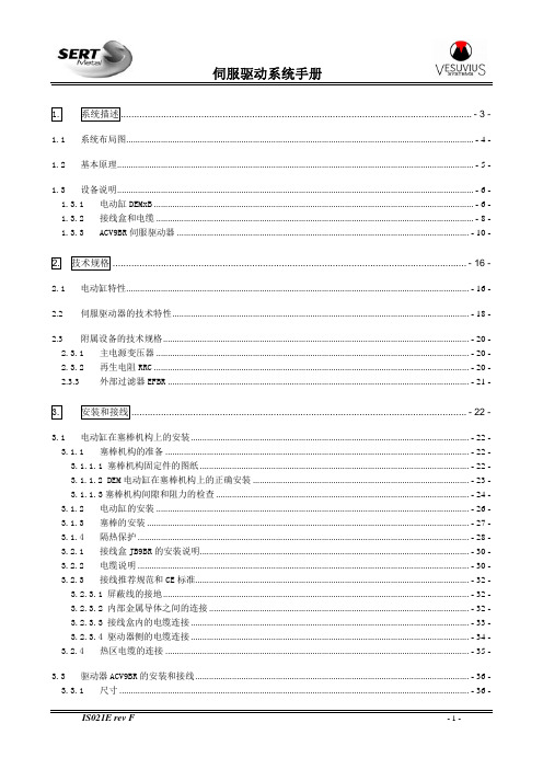
1.系统描述...................................................................................................................................- 3 -1.1系统布局图.......................................................................................................................................................- 4 -1.2基本原理...........................................................................................................................................................- 5 -1.3设备说明...........................................................................................................................................................- 6 -1.3.1电动缸DEMxB...........................................................................................................................................- 6 -1.3.2接线盒和电缆..........................................................................................................................................- 8 -1.3.3ACV9BR伺服驱动器...............................................................................................................................- 10 -2.技术规格....................................................................................................................................- 16 -2.1电动缸特性.....................................................................................................................................................- 16 -2.2伺服驱动器的技术特性.................................................................................................................................- 18 -2.3附属设备的技术规格.....................................................................................................................................- 20 -2.3.1主电源变压器........................................................................................................................................- 20 -2.3.2再生电阻RRC.........................................................................................................................................- 20 -2.3.3外部过滤器EFBR...................................................................................................................................- 21 -3.安装和接线.............................................................................................................................- 22 -3.1电动缸在塞棒机构上的安装.........................................................................................................................- 22 -3.1.1塞棒机构的准备....................................................................................................................................- 22 -3.1.1.1 塞棒机构固定件的图纸.....................................................................................................................- 22 -3.1.1.2 DEM电动缸在塞棒机构上的正确安装..............................................................................................- 23 -3.1.1.3塞棒机构间隙和阻力的检查..............................................................................................................- 24 -3.1.2电动缸的安装........................................................................................................................................- 26 -3.1.3塞棒的安装............................................................................................................................................- 27 -3.1.4隔热保护................................................................................................................................................- 28 -3.2.1接线盒JB9BR的安装说明.....................................................................................................................- 30 -3.2.2电缆说明................................................................................................................................................- 30 -3.2.3接线推荐规范和CE标准.......................................................................................................................- 32 -3.2.3.1 屏蔽线的接地.....................................................................................................................................- 32 -3.2.3.2 内部金属导体之间的连接.................................................................................................................- 32 -3.2.3.3 接线盒内的电缆连接.........................................................................................................................- 33 -3.2.3.4 驱动器侧的电缆连接.........................................................................................................................- 34 -3.2.4热区电缆的连接....................................................................................................................................- 35 -3.3驱动器ACV9BR的安装和接线.......................................................................................................................- 36 -3.3.1尺寸........................................................................................................................................................- 36 -3.3.2安装、定位和冷却................................................................................................................................- 37 -3.3.3电源的连接............................................................................................................................................- 39 -4.操作........................................................................................................................................- 40 -4.1手动模式.........................................................................................................................................................- 40 -4.2远程工作模式.................................................................................................................................................- 41 -4.3自动模式.........................................................................................................................................................- 41 -4.4塞棒关闭和安全装置.....................................................................................................................................- 42 -4.4.1塞棒关闭................................................................................................................................................- 42 -4.4.2断开电机电源(可选项).....................................................................................................................- 42 -4.5运行故障的处理.............................................................................................................................................- 43 -5.维护........................................................................................................................................- 44 -5.1检查周期.........................................................................................................................................................- 44 -5.2电动缸的检查和维护.....................................................................................................................................- 45 -5.3推荐的备件.....................................................................................................................................................- 49 -5.4伺服驱动器的故障代码.................................................................................................................................- 53 -5.5故障的数字输出代码.....................................................................................................................................- 57 -5.6驱动器复位和状态显示.................................................................................................................................- 58 -5.7没有报警显示时的故障排除.........................................................................................................................- 59 -6.辅助设备.................................................................................................................................- 61 -6.1DEM系列电动缸的测试台..............................................................................................................................- 61 -6.2塞棒机构MQS..................................................................................................................................................- 61 -1.系统描述SERT的塞棒执行器系统用于控制塞棒和塞棒机构的位置,以控制流入结晶器的钢水的流量。
- 1、下载文档前请自行甄别文档内容的完整性,平台不提供额外的编辑、内容补充、找答案等附加服务。
- 2、"仅部分预览"的文档,不可在线预览部分如存在完整性等问题,可反馈申请退款(可完整预览的文档不适用该条件!)。
- 3、如文档侵犯您的权益,请联系客服反馈,我们会尽快为您处理(人工客服工作时间:9:00-18:30)。
前言
感谢您购买并使用 BONMET 伺服驱动器,本使用说明书将主要为您 介绍以下内容: ● 伺服驱动器的组成说明 ● 伺服驱动器的安装与检查 ● 伺服驱动器的所有参数说明 ● 伺服驱动器的控制功能以及调整方法 ● 故障处理方法 ● 检测与维护 在使用前,谨请认真阅读本使用说明书,同时,请您在熟读本产品安 全注意事项的基础上使用。此外,请将它妥善放置在安全的地方以便 随时查阅。如果您在使用上仍有问题,请咨询本公司客服中心寻求技 术支持。
则可能导致火灾。 · 当使用制动电阻时,如果出现错误的信号,请切断主电源。否则,制动电阻故障或类
似故障可能使制动电阻过热,导致火灾。压与驱动器器的额定电压是否一致。 · 请勿将 AC 电源直接连接到伺服电机。 · 确保端子极性正确。 · U、V、W 的接线必须与电机端子 2、3、4 一一对应,注意不能用调换三相端子的方法来
第 2 章 安装与接线...................................................................................................................... 10
2.1 安装场所 ............................................................................................................................... 10 2.2 安装方向和空间 ................................................................................................................... 10 2.3 连接图 ................................................................................................................................... 11
使电机反转,这一点与异步电机完全不同。
● 运行和调试
注意
· 散热片及制动电阻因高温请勿触摸。 · 请勿过度更改参数设置,可能导致运行不稳定。 · 运行过程中,请勿触摸伺服电机的旋转部分。
● 其他
· 绝对不要自行改造伺服驱动器。
注意
2
目录
第 1 章 型号与规格........................................................................................................................6
3.5.1 开关量输入接口 ........................................................................................................... 18 3.5.2 开关量输出接口 ........................................................................................................... 19 3.5.3 脉冲量输入接口 ........................................................................................................... 19 3.5.4 模拟输入接口 ............................................................................................................... 21 3.5.5 编码器信号输出接口 ................................................................................................... 23 3.5.6 编码器 Z 信号集电极开路输出接口 ..........................................................................24 3.5.7 伺服电机光电编码器输入接口 ................................................................................... 24 3.6 制动电阻端子 P、PC、P1 ....................................................................................................24 3.7 外接电容端子 G ....................................................................................................................24
第 3 章 接口 ................................................................................................................................. 14
3.1 驱动器电源端子 ................................................................................................................... 14 3.2 编码器信号输入端子 CN1 ....................................................................................................14 3.3 控制信号输入/输出端子 CN2 ..............................................................................................15 3.4 串口联机线端子 COM/CN3 ....................................................................................................18 3.5 输入/输出接口类型 .............................................................................................................18
2.3.1 SA3L04C 型驱动器连接图............................................................................................11 2.3.2 SA3L06B/SA3L10B 型驱动器连接图............................................................................11 2.3.3 SA3L15C/ SA3L25C 型驱动器连接图..........................................................................12 2.3.4 SA3H10C 型驱动器连接图............................................................................................12 2.4 电缆类型 ............................................................................................................................... 13 2.5 配线方法 ............................................................................................................................... 13