全极型低功耗霍尔元件YS4913使用说明书
霍尔元件技术指标参考

霍尔元件技术指标1相关参数1.1封装形式 TO-92(三脚插片),SOT-23(三脚贴片)。
还有SIP-4(四脚插片),SOT-143(四脚贴片)和SOT-89(四脚贴片) 1.2电源 有3.5~24V ,2.5~3.5V ,2.5~5V1.3灵敏度Kh 数量级在C m /1033,且数值越大灵敏度越高1.4霍尔电势温度αα越小,设备精确度越大(必要时可以增加温度补偿电路)1.5额定控制电流cI 一般在几mA~几十mA ,尺寸越大其值越大(尺寸大的可达几百mA )1.6型号 开关型的、线性的、单极性的、双极性的。
双极开关霍尔元件:177A 、177B 、177C 单极霍尔开关元件:AH175、732、1881、S41、SH12AF 、3144、44E 、3021、137、AH137、AH284线性霍尔元件:3503、S496B 、49E 锁定霍尔元件:ATS175、AH173、SS413A 、3172、3075互补双输出开关霍尔元件:276A 、276B 、276C 、277A 、277B 、277C 信号霍尔元件:211A 、211B 、211C 微功耗霍尔元件:TEL4913、TP4913、A3212、A3211。
(具体霍尔开关元件见附录)1.7输入电阻和输出电阻 一般在几Ω到几百Ω,且输入电阻要大于输出电阻1.8外接上拉电阻 一般大于1K Ω。
对一般TTL 电路,由于其高电平电压较低,用于驱动CMOS 电路时,增加上拉电阻,可以提高其高电平的电压。
常用的阻值是4.7k 或10k 。
上拉电阻的是接在1脚电源Vcc 和3脚信号输出Vout 之间。
1.9功能分类 按照霍尔器件的功能可将它们分为: 霍尔线性器件 和 霍尔开关器件 。
前者输出模拟量,后者输出数字量。
都是输出高电平脉冲信号,不同的是开关型相当于到GS 设定值时电平反转;线性的可能是电压逐渐变化,到一定时使后处理电路输出反电平。
一般建议用线性的,开关型常因为温度等原因使得设定值漂移,导致灵敏度下降。
LN4913_C南麟中文版规格书CMOS 无极性高灵敏度微功耗霍尔开关
1.000
1.200
0.800
1.000
0.200MIN
0.200
0.300
0.500TYP
0.174
0.326
Dimensions In Inches
Min
Max
0.014
0.018
0.000
0.002
0.005REF
0.056
0.062
0.076
0.082
0.039
0.047
0.031
0.039
VDD 1 VOUT 2
3 GND
DFN2020-3L (TOP VIEW)
SOT23-3L/TSOT23-3L 2 3 1 -
引脚号 DFN1520-6L
5 3 2 1,4,6
Sensitive Area (感应区)
DFN2020-3L 2 3 1 -
TO-92S (Front View)
引脚名
VOUT GND VDD NC
CMOS 无极性高灵敏度微功耗霍尔开关
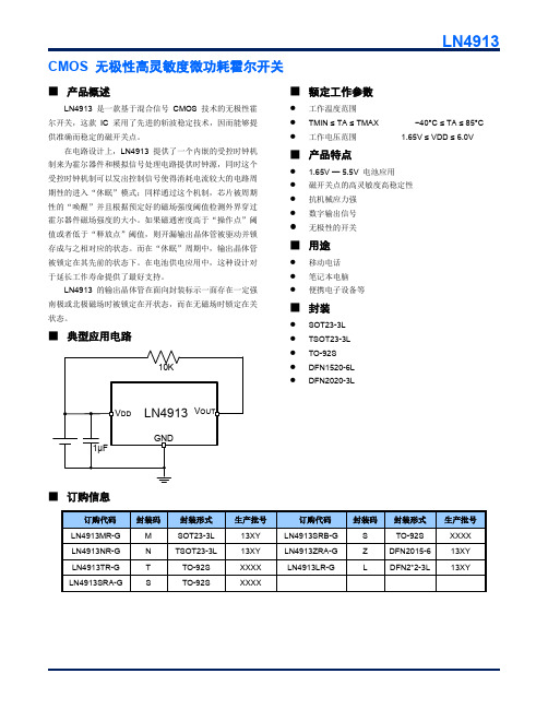
LN4913
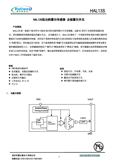
■ 产品概述
LN4913 是一款基于混合信号 CMOS 技术的无极性霍 尔开关,这款 IC 采用了先进的斩波稳定技术,因而能够提 供准确而稳定的磁开关点。
在电路设计上,LN4913 提供了一个内嵌的受控时钟机 制来为霍尔器件和模拟信号处理电路提供时钟源,同时这个 受控时钟机制可以发出控制信号使得消耗电流较大的电路周 期性的进入“休眠”模式;同样通过这个机制,芯片被周期 性的“唤醒”并且根据预定好的磁场强度阈值检测外界穿过 霍尔器件磁场强度的大小。如果磁通密度高于“操作点”阈 值或者低于“释放点”阈值,则开漏输出晶体管被驱动并锁 存成与之相对应的状态。而在“休眠”周期中,输出晶体管 被锁定在其先前的状态下。在电池供电应用中,这种设计对 于延长工作寿命提供了最好支持。
霍尔元件简介
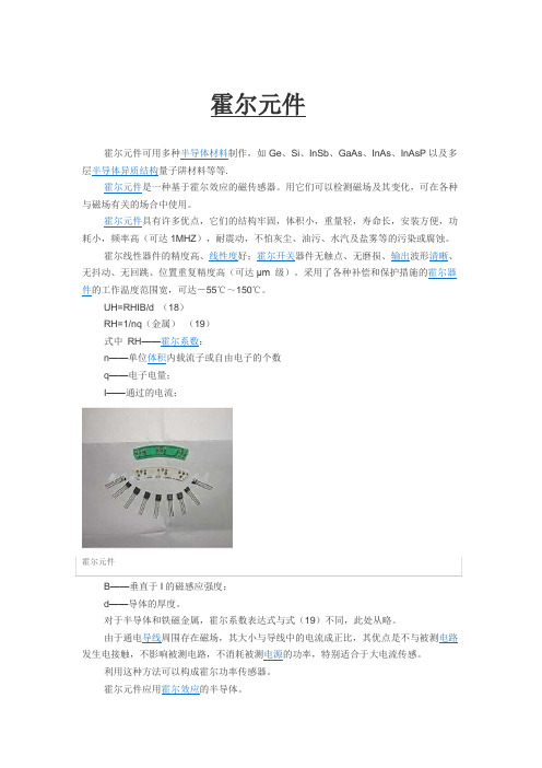
2工作原理霍尔元件应用霍尔效应的半导体。
所谓霍尔效应,是指磁场作用于载流金属导体、半导体中的载流子时,产生横向电位差的物理现象。
金属的霍尔效应是1879年被美国物理学家霍尔发现的。
当电流通过金属箔片时,若在垂直于电流的方向施加磁场,则金属箔片两侧面会出现横向电位差。
半导体中的霍尔效应比金属箔片中更为明显,而铁磁金属在居里温度以下将呈现极强的霍尔效应。
利用霍尔效应可以设计制成多种传感器。
霍尔电位差UH的基本关系为:UH=RHIB/d (1)RH=1/nq(金属)(2)式中RH――霍尔系数;n――单位体积内载流子或自由电子的个数;q――电子电量;I――通过的电流;B――垂直于I的磁感应强度;d――导体的厚度。
对于半导体和铁磁金属,霍尔系数表达式和式(2)不同,此处从略。
由于通电导线周围存在磁场,其大小和导线中的电流成正比,故可以利用霍尔元件测量出磁场,就可确定导线电流的大小。
利用这一原理可以设计制成霍尔电流传感器。
其优点是不和被测电路发生电接触,不影响被测电路,不消耗被测电源的功率,特别适合于大电流传感。
若把霍尔元件置于电场强度为E、磁场强度为H的电磁场中,则在该元件中将产生电流I,元件上同时产生的霍尔电位差和电场强度E成正比,如果再测出该电磁场的磁场强度,则电磁场的功率密度瞬时值P可由P=EH确定。
利用这种方法可以构成霍尔功率传感器。
如果把霍尔元件集成的开关按预定位置有规律地布置在物体上,当装在运动物体上的永磁体经过它时,可以从测量电路上测得脉冲信号。
根据脉冲信号列可以传感出该运动物体的位移。
若测出单位时间内发出的脉冲数,则可以确定其运动速度。
[1]3元件特性1、霍尔系数(又称霍尔常数)RH在磁场不太强时,霍尔电势差UH与激励电流I和磁感应强度B的乘积成正比,与霍尔片的厚度δ成反比,即UH =RH*I*B/δ,式中的RH称为霍尔系数,它表示霍尔效应的强弱。
另RH=μ*ρ即霍尔常数等于霍尔片材料的电阻率ρ与电子迁移率μ的乘积。
全极低功耗霍尔开关SS248使用手册
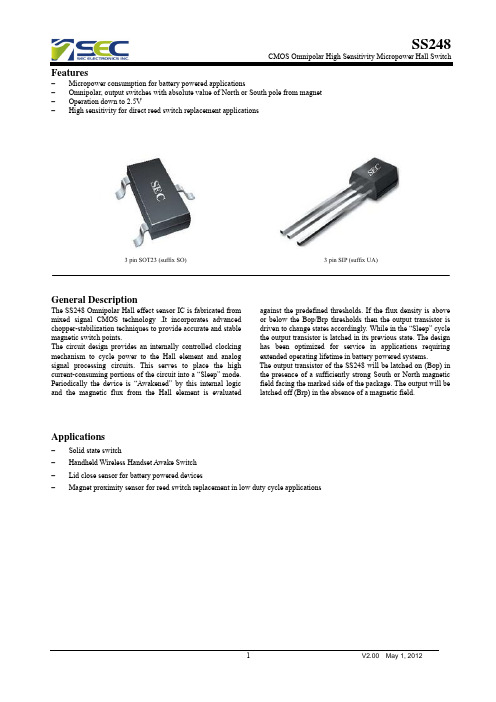
CMOS Omnipolar High Sensitivity Micropower Hall Switch
Features
Micropower consumption for battery powered applications Omnipolar, output switches with absolute value of North or South pole from magnet Operation down to 2.5V High sensitivity for direct reed switch replacement applications
VDD IDD IOUT VSAT TAW TSL
Operating Average
IOUT=1mA Operating Operating
Min
Typ
Max
Units
2.5
3
5.5
V
5
μA
1.0
mA
0.4
V
175
μS
70
mS
Magnetic Characteristics
Output Voltage(V)
PARAMETER Operating Point Release Point Hysteresis
Symbol
Min
Bop
-
Brp
+/-5
Bhys
-
SS248
CMOS Omnipolar High Sensitivity Micropower Hall Switch
Type +/-35 +/-21
DC Electrical Characteristics
三相直流无刷霍尔电机驱动器说明书
前言本款产品适合驱动持续工作电流在10A以下、额定电压范围在12V~40V之间的任何一款三相直流无刷霍尔电机。
具有免维护、长寿命、低速下总能保持最大转矩等优势。
本产品广泛应用于针织设备、医疗设备、食品机械、电动工具、园林机械、智能家居等电气自动化控制领域。
本手册阐述了该驱动器的的功能、安装、调试、维护、运行等方面的内容。
使用产品前,请认真阅读本手册并熟知本产品的安全注意事项。
在使用本款产品时,若有疑问,请仔细查阅产品说明书或致电我公司售后服务部,我们将竭诚为您服务。
安全注意事项警示标志:危险:表示该操作错误可能危及人身安全!注意:表示该操作错误可能导致设备损坏!注意事项:安装:防止灰尘、腐蚀性气体、导电物体、液体及易燃物侵入,并保持良好的散热条件。
接线:请由专业人员仔细阅读完使用说明之后进行接线作业;接线必须在电源断开的状态下进行,防止电击。
通电前:接通电源前检查并保证接线的准确无误;请确认输入电源与驱动器的额定工作电压及极性是否一致;通电中:驱动器接通电源后,请勿直接接触输出端子,有的端子上有高电压,非常危险;请确保在驱动器指示灯熄灭后再对驱动器的接线端子进行插拔;请勿对驱动器随意进行耐高压与绝缘性能试验;请勿将电磁接触器、电磁开关接到输出回路。
目录前言 (1)安全注意事项 (2)目录 (3)一.概述 (5)1.型号说明 (5)2.功能参数 (5)3.功能特点 (6)二.端口说明 (7)1.接口定义 (7)2.接线示意图 (8)3.安装尺寸 (9)三.功能与使用 (10)1.出厂说明 (10)2.操作步骤说明 (10)2.1外置电位器调速 (11)2.2外部电压调速 (11)2.3外部PWM信号调速 (11)2.4CAN总线控制 (11)3.功能端子说明 (12)3.1F/R端子:正反转功能 (12)3.2EN端子:使能功能 (12)3.3BRK端子:刹车抱死功能 (12)3.4SV端子:外部调速端子 (13)3.5PG端子:电机转速信号输出 (13)3.6ALM端子:报警输出 (13)3.7PWR/ALM:指示灯 (14)一.概述本款驱动器适用于对直流无刷有霍尔电机进行转速控制,其最大的优点是在低速时总能控制电机保持最大转矩。
OMEGA M-4913-K 产品说明书

Shop online at e-mail:**************For latest product manuals: NORWALK, CTUser’s GuideM12 CONNECTOR STYLEPRS SERIESSpring Loaded SanitaryRTD Sensors with ThermowellsGENERAL DESCRIPTIONThe OMEGA PRS series sensors are designed for use in Sanitary Clean-In-Place (CIP) systems, and are supplied with a Tri-Grip® flanged thermowell for easy installation into Food, Dairy and Biopharmaceutical systems. These sensors are supplied with a stainless steel thermowell, a spring loaded probe assembly with an M12 connector When assembled, the probe is spring loaded into the thermowell. The probe contains a 4-wirePT100 Platinum RTD (Resistance Temperature Detector) that meets the resistance vs. temperature characteristics and Class A requirements of IECtemperature table.PROCESS CONNECTIONThis sensor has a thermowell that includes aTri-Grip® flange so it can be installed into existing process connections. A commercially available gasket is placed between the thermowell flange and process connection, with a clamp used to complete the connection as shown above.The Thermowell is made from 316L Stainless Steel, with wetted surfaces that have a surface WIRING CONFIGURATION:The Omega PRS Style sensors are supplied with 4-Pin, M12 connectors for convenient connection to your process instrumentation. The wiring arrangement of the connector pins are as shown in the detail below.For 4-wire PT100 RTD connections, simply connect the sensor to the instrumentation using a 4-wire extension cable (not supplied, Note: RTD sensors have no polarity). This 4-wire device can also be used with 2-wire or 3-wire devices by connecting only to those pins that are needed (see diagram below).Resistance Vs. Temperature Table: (Resistance Values Stated in Ohms)Temperature °C0123456789-5080.3279.9279.5279.1378.7378.3377.9377.5477.1476.74-4084.2883.8883.4883.0982.6982.3081.9081.5081.1180.71-3088.2287.8387.4487.0486.6586.2585.8685.4685.0784.67-2092.1691.7791.3790.9890.5990.1989.8089.4189.0188.62-1096.0995.6995.3094.9194.5294.1393.7393.3492.9592.55100.0099.6199.2298.8398.4498.0497.6597.2696.8796.480100.00100.39100.78101.17101.56101.95102.34102.73103.12103.5110103.90104.29104.68105.07105.46105.85106.24106.63107.02107.4020107.79108.18108.57108.96109.35109.73110.12110.51110.90111.2930111.67112.06112.45112.83113.22113.61114.00114.38114.77115.1540115.54115.93116.31116.70117.08117.47117.86118.24118.63119.0150119.40119.78120.17120.55120.94121.32121.71122.09122.47122.8660123.24123.63124.01124.39124.78125.16125.54125.93126.31126.6970127.08127.46127.84128.22128.61128.99129.37129.75130.13130.5280130.90131.28131.66132.04132.42132.80133.18133.57133.95134.3390134.71135.09135.47135.85136.23136.61136.99137.37137.75138.13100138.51138.88139.26139.64140.02140.40140.78141.16141.54141.91110142.29142.67143.05143.43143.80144.18144.56144.94145.31145.69120146.07146.44146.82147.20147.57147.95148.33148.70149.08149.46130149.83150.21150.58150.96151.33151.71152.08152.46152.83153.21140153.58153.96154.33154.71155.08155.46155.83156.20156.58156.95150157.33157.70158.07158.45158.82159.19159.56159.94160.31160.68160161.05161.43161.80162.17162.54162.91163.29163.66164.03164.40170164.77165.14165.51165.89166.26166.63167.00167.37167.74168.11180168.48168.85169.22169.59169.96170.33170.70171.07171.43171.80190172.17172.54172.91173.28173.65174.02174.38174.75175.12175.49200175.86176.22176.59176.96177.33177.69178.06178.43178.79179.16210179.53179.89180.26180.63180.99181.36181.72182.09182.46182.82220183.19183.55183.92184.28184.65185.01185.38185.74186.11186.47230186.84187.20187.56187.93188.29188.66189.02189.38189.75190.11240190.47190.84191.20191.56191.92192.29192.65193.01193.37193.74250194.10194.46194.82195.18195.55195.91196.27196.63196.99197.35260197.71198.07198.43198.79199.15199.51199.87200.23200.59200.95For Determining Resistance from Temperature (0°C and above):R t = R 0(1 + A t + B t 2)where:R t = Sensor Resistance at Temperature (°C)R 0 = Sensor resistance at 0°C = (100 Ohms Nominal)A = 3.9083 x 10B = 5.775 x 10⁻³ °C -1-7 °C -2For Determining Temperature From Resistance (0°C and above):t = [sqrt(A 2-4B(1-R t /R 0))-A]/2B = °C where:t = Temperature at Sensor Resistance R t A, B, R 0 and R t per aboveClass A Tolerance = ± (0.15 + 0.002t) = °C With t = temperature in °C regardless to sign.M-4913-K Instruction Manual for M12 Connector Style PRS Series Spring LoadedSanitary RTD Sensors With ThermowellsDISCLAIMERIf the unit malfunctions, it must be returned to the factory for evaluation. OMEGA’s Customer Service Department will issue an Authorized Return (AR) number immediately upon phone or written request. Upon examination by OMEGA, if the unit is found to be defective, it will be repaired or replaced at no charge. OMEGA’s WARRANTY does not apply to defects resulting from any action of the purchaser, including but not limited to mishandling, improper interfacing, operation outside of design limits, improper repair, or unauthorized modification. This WARRANTY is VOID if the unit shows evidence of having been tampered with or shows evidence of having been damaged as a result of excessive corrosion; or current, heat, moisture or vibration; improper specification; misapplication; misuse or other operating conditions outside of OMEGA’s control. Components in which wear is not warranted, include but are not limited to contact points, fuses, and triacs.OMEGA is pleased to offer suggestions on the use of its various products. However, OMEGA neither assumes responsibility for any omissions or errors nor assumes liability for any damages that result from the use of its products in accordance with information provided by OMEGA, either verbal or written. OMEGA warrants only that the parts manufactured by the company will be as specified and free of defects. OMEGA MAKES NO OTHER W ARRANTIES OR REPRESENTATIONS OF ANY KIND W HATSOEVER, EXPRESSED OR IMPLIED, EXCEPT THAT OF TITLE, AND ALL IMPLIED W ARRANTIES INCLUDING ANY W ARRANTY OF MERCHANTABILITY AND FITNESS FOR A PARTICULAR PURPOSE ARE HEREBY DISCLAIMED. LIMITATION OF LIABILITY: The remedies of purchaser set forth herein are exclusive, and the total liability of OMEGA with respect to this order, whether based on contract, warranty, negligence, indemnification, strict liability or otherwise, shall not exceed the purchase price of the component upon which liability is based. In no event shall OMEGA be liable for consequential, incidental or special damages.CONDITIONS: Equipment sold by OMEGA is not intended to be used, nor shall it be used: (1) as a “Basic Component” under 10 CFR 21 (NRC), used in or with any nuclear installation or activity; or (2) in medical applications or used on humans. Should any Product(s) be used in or with any nuclear installation or activity, medical application, used on humans, or misused in any way, OMEGA assumes no responsibility as set forth in our basic WARRANTY / DISCLAIMER language, and, additionally, purchaser will indemnify OMEGA and hold OMEGA harmless from any liability or damage whatsoever arising out of the use of the Product(s) in such a manner.RETURN REQUESTS / INQUIRIESDirect all warranty and repair requests/inquiries to the OMEGA Customer Service Department. BEFORE RET URNING ANY PRODUCT(S) TO OMEGA, PURCHASER MUST OBTAIN AN AUTHORIZED RETURN (AR) NUMBER FROM OMEGA’S CUST OMER SERVICE DEPART MENT (IN ORDER T O AVOID PROCESSING DELAYS). T he assigned AR number should then be marked on the outside of the return package and on any correspondence.T he purchaser is responsible for shipping charges, freight, insurance and proper packaging to prevent breakage in transit.FOR WARRANTY RETURNS, please have the following information available BEFORE contacting OMEGA:1. P urchase Order number under which the product was PURCHASED,2. M odel and serial number of the product under warranty, and 3. R epair instructions and/or specific problems relative to the product.FOR NON-WARRANTY REPAIRS, consult OMEGA for current repair charges. Have the following information available BEFORE contacting OMEGA:1.Purchase Order number to cover the COST of the repair,2.Model and serial number of the product, and3. R epair instructions and/or specific problems relative to the product.OMEGA’s policy is to make running changes, not model changes, whenever an improvement is possible. T his affords our customers the latest in technology and engineering. OMEGA is a trademark of OMEGA ENGINEERING, INC.© Copyright 2018 OMEGA ENGINEERING, INC. All rights reserved. This document may not be copied, photocopied, reproduced, translated, or reduced to any electronic medium or machine-readable form, in whole or in part, without the prior written consent of OMEGA ENGINEERING, INC.***********************The information contained in this document is believed to be correct, but OMEGA accepts no liability for any errors it contains, and reserves the right to alter specifications without notice.Servicing North America:U.S.A.Omega Engineering, Inc.Headquarters:Toll-Free: 1-800-826-6342 (USA & Canada only)Customer Service: 1-800-622-2378 (USA & Canada only) Engineering Service: 1-800-872-9436 (USA & Canada only) Tel: (203) 359-1660 Fax: (203) 359-7700 e-mail:**************For Other Locations Visit /worldwideM4913-K /0418。
HAL13S低压微功耗霍尔元件全极霍尔开关4913
(VDD=2.7V,除非特别说明,Ta=25℃)
符号 BOPS BOPN BRPS BRPN BHYS
最小 2 -5 1 -2.6 0.8
最大 5 -2 4.2 -1.2 1.6
单位 mT mT mT mT mT
6
值 -0.3—6.0 -1—4.5 -0.3—6.0 -1—2 -45—150 -150 4000
单位 V mA V mA ℃ ℃ V
AC/DC 特性(VDD=3V,除非特别说明,Ta=25℃) 符号 VDD ISAVG ISOPAVG ISOPT ISSTB VQSAT IQLEAK tr rf top tstb top/tstb tstu 参数 供电电压 平均供电电流 操作时间内平均电流 操作时间内峰值电流 关状态时供电电流 输出饱和电压 输出漏电流 输出上升沿时间 输出下降沿时间 工作时间 关状态工作时间 占空比 芯片启动时间 RL=2.7KΩ CL=10pF RL=2.7KΩ CL=10pF 25 60 IQ=1mA 1 1.9 0.13 0.01 0.5 0.1 100 140 0.071 12 20 测试条件 — 最小 2.4 1 0.5 典型 — 3 2.0 最大 6.0 10 3.5 4.5 8 0.4 1 1 1 160 240 单位 V uA mA mA uA V uA us us us ms % us
此图仅为典型应用电路,而不代表引脚功能图!
SOT-23-3/TSOT-23-3 (TOP VIEW)
GND
2
Sensitive Area (感应区)
Marking
13 1
VS
XY
Date Code
3
Q
LN4913MR
项目 工作电压 工作电流 输出电压 输出电流 贮存温度 结点温度 ESD 参数
霍尔开关集成电路 SDC141 数据手册说明书
数据手册概述SDC141是一款锁定型的霍尔开关集成电路,由反向电路保护器、高稳定度的电压稳压器、霍尔电压发生器、差分放大器、史密特触发器和集电极开路输出级组成。
可广泛应用于三相无刷直流电机、无刷直流风扇、电表、焊接设备、家用电器装置、速度测量等场合。
特点⏹ 宽范围工作电压:4V ~24V ⏹ 内置温度补偿电路 ⏹ 内置电源反向电压保护功能 ⏹ 工作温度范围:-55℃~150℃ ⏹ 开集电极输出 ⏹ 最大20mA 输出电流⏹ 工作速度:0~100kHz 以上⏹封装形式:TO-92S 、SOT-23-3应用⏹ 三相直流无刷电机 ⏹ 高性能数字开关⏹ 流速计⏹速度检测图1. 封装形式SOT-23-3TO-92S SD CO NFID E N T I AL D OCUM EN T数据手册管脚描述GND VCCOUTPackage: SOT-23-3OUT VCCGND Package: TO-92S图2 管脚排布编号名称 功能 SOT-23-3TO-92S 1 1 VCC 电源 3 2 GND 地 23OUT输出脚表1. 管脚描述功能框图VCCGNDOUT图3. 功能框图SD CID E N T I AL D EN T数据手册订购信息SDC141Circuit TypeMagnetic Characteristics: A/a/BE1: Pb-freeG1: Halogen-freeTR: Tape ReelBlank: BulkX X-XPackageTO-92S: ZSSOT-23-3: JX封装温度范围产品编号标识编号包装形式无铅无卤无铅无卤TO-92S-55℃~150℃SDC141AZS-E1 SDC141AZS-G1 S41 S41G 袋装SDC141aZS-E1 SDC141aZS-G1 S41 S41G 袋装SDC141BZS-E1 SDC141BZS-G1 S41 S41G 袋装SOT-23-3 SDC141AJTR-E1 SDC141AJTR-G1 S41 S41G 编带SDC141aJTR-E1 SDC141aJTR-G1 S41 S41G 编带SDC141BJTR-E1 SDC141BJTR-G1 S41 S41G 编带S D CC ON FI DE NT IA LD OC UME NT数据手册极限参数(注意:应用不要超过最大值,以防止损坏。