透镜设计导论——ZEMAX设计实例参考作案
zemax设计 - 单透镜设计

单透镜设计透镜参数:
1.焦距为100mm。
2.相对孔径为1/5。
3.全视场2ω为10度。
4.物距为无穷远。
5.选用K5玻璃。
1.系统二维图
2.系统三维图
3.光线扇面
4.场曲
5.由一个物点发出的光线经光学系统后,由于像差的存在,像面上
不再是一个集合点,而是一个弥散斑,称之为点列图。
常用点列图的密集程度衡量光学系统的成像质量。
将Show Airy Disk选中,可得到下面的图像:
可以看到爱里斑直径值为5.732,大部分的点都落在“Airy Disk”内。
6.MTF曲线
①MTF曲线越高越好,图中MTF曲线所占面积大于图的面积的1/2,
说明MTF曲线足够高。
②MTF曲线越平越好,图中MTF曲线足够平滑。
③S曲线与T曲线越重合越好,图中S曲线和T曲线比较重合,说明
镜头的像散较小。
透镜设计导论——ZEMAX设计实例参考作案
光学系统 Kingslake,R.,Optical Systems Design. New York:Academic Press 1983. Smith,W.,Modern Optical Engineering. New York:McGraw-Hill,1966.
史料 Kingslake,R.,A History of the Photographic Lens. New York: Academic Press,1989. King,H.C.,The History of the Telescope. Cambridge:Sky Publishing Corporation,1955.
New York:
几何光学 hecht,E. and Zajac,A,Optics (Firs edition). Boston:Addison-Wesley. 1974. Pedrotii,F.and Pedrotti,L.,Introduction to Optics (Second edition). New Jersey:Prentice Hall,1993. Sears,F,Optics (Third edition). Boston:Addison-Wesley,1958.
343
附录 D 术语表 Lateral Color: Chromatic aberration associated with the chief ray. Magnification: Ratio of image height to object height. Marginal Ray: Ray from the axial object point to the rim of the entrance pupil. Merit Function: A number that summarizes the state of optimization of an imaging system. The lower the number, the better the optimization. Modulation Transfer Function (MTF): A measure of image contrast as a function of spatial frequency. Null Lens: A refractive or reflective optical system interposed between a test point and an aspheric mirror in a radius of curvature test configuration. Compensates for the spherical aberration associated with the normals to the mirror surface. Numerical Aperture: Defines the light collection capability of an optical system in object space for a finite object distance. Optical Path Length: The actual path length multiplied by the refractive index within that path. Optical Path Difference: The separation between an aberrated wavefront and a reference sphere at some point in the exit pupil. Optical Power: The reciprocal of focal length. Principal Plane(s): An optical imaging system has a pair of principal planes (front and rear). These planes, along with a knowledge of focal point locations, can represent the first order imaging properties of the system (no matter how complicated that system may be). The image point location of any object point can be determined via simple graphical ray tracing techniques. Paraxial Plane: For an optical imaging system,trace rays which lie close to the optical axis through the system for a given axial object point. The convergence point of such rays in image space defines the location of the paraxial
zemax光学设计案例

zemax光学设计案例
Zemax光学设计案例。
在光学设计领域,Zemax是一个非常优秀的光学设计软件,它能够帮助工程师
们进行光学系统的设计、优化和分析。
下面,我们将介绍一个使用Zemax进行光
学设计的案例,以便更好地了解Zemax软件的应用和优势。
在这个案例中,我们需要设计一个具有特定光学性能的摄像头透镜系统。
首先,我们需要明确设计要求和约束条件,然后利用Zemax软件进行光学系统的建模和
优化。
在建模过程中,我们需要考虑透镜的曲率、厚度、材料等参数,同时还需要考虑系统的光路布局、光学元件的位置和角度等因素。
利用Zemax的光学设计工具,我们可以对透镜系统进行快速而准确的建模和分析。
通过Zemax的光学优化算法,我们可以对系统的光学性能进行优化,以满足
设计要求。
同时,Zemax还提供了丰富的光学分析工具,可以对系统的像差、光学传递函数、热像模拟等进行全面的分析和评估。
在这个案例中,我们利用Zemax软件成功设计出了一个具有优秀光学性能的摄像头透镜系统。
通过对系统的建模、优化和分析,我们实现了对系统光学性能的精确控制和调节,最终达到了设计要求。
这充分展示了Zemax软件在光学设计领域
的强大功能和广泛应用价值。
总的来说,Zemax是一款非常优秀的光学设计软件,它能够帮助工程师们实现
复杂光学系统的设计、优化和分析。
通过这个案例,我们可以更好地了解Zemax
软件的应用和优势,相信在未来的光学设计工作中,Zemax将会发挥越来越重要的作用,为光学工程领域的发展做出更大的贡献。
zemax光学设计例子

在光学设计中,Zemax是一款非常受欢迎的软件,它提供了强大的工具和功能,可以帮助设计师轻松地完成各种光学设计任务。
本文将通过一个具体的例子,向大家展示如何使用Zemax进行光学设计。
一、设计背景我们假设需要设计一款望远镜,需要观察远处的星空。
望远镜的主要性能指标包括放大倍率、像差和亮度。
我们需要通过Zemax软件,找到最佳的光学系统方案,以达到最佳的观察效果。
二、设计步骤1.建立基本光学系统模型:在Zemax中,我们需要建立一个基本的光学系统模型,包括望远镜的主镜和次镜。
可以通过手动输入镜片数据或者使用预设的镜片库来建立模型。
2.调整参数:在Zemax中,我们可以调整各种参数来优化望远镜的性能。
例如,可以通过调整放大倍率和亮度参数来找到最佳的观察效果。
3.检测像差:在调整参数后,我们需要检测望远镜的像差。
Zemax 提供了强大的像差检测功能,可以帮助我们找到镜片上的缺陷和误差。
4.优化镜片:根据检测结果,我们可以对镜片进行优化。
可以通过添加或删除镜片、调整镜片位置和角度等方式来改善望远镜的性能。
5.模拟观察:在完成镜片优化后,我们可以模拟观察望远镜的成像效果。
可以通过调整望远镜的焦距和观察角度来查看不同情况下的成像效果。
6.调整和优化:根据模拟观察结果,我们可以再次调整和优化望远镜的设计。
直到达到满意的观察效果为止。
三、设计结果经过一系列的设计和优化步骤,我们得到了一个满意的光学设计方案。
该方案包括两片反射镜,放大倍率为10倍,像差在可接受范围内,亮度较高。
通过Zemax模拟观察,成像效果清晰、稳定,符合我们的预期。
四、总结通过这个具体的例子,我们展示了如何使用Zemax进行光学设计。
虽然只是一个简单的望远镜设计,但是它涵盖了光学设计的基本步骤和技巧。
在实际应用中,光学设计需要考虑的因素很多,例如环境因素、成本预算、材料选择等。
Zemax提供了丰富的工具和功能,可以帮助设计师轻松应对各种挑战。
Zemax全新菲涅耳透镜设计

Zemax○R菲涅耳透镜设计工具(UDS)--VR/AR解决方案Zemax○R自定义面型(UDS)提供了复杂曲面建模的解决方案,使得复杂建模成为可能。
下面在序列模式下以菲涅耳透镜为例,简要概述其建模,仿真及优化能力。
序列模式下,对菲涅耳透镜的建模尤其是对锯齿建模一直是个难点,以前一直没有好的解决方案。
以前只能通过非序列模式,或者混合序列-非序列模式采用内置的Fresnel 1对锯齿建模。
但非序列模式下(或者混合非序列模式下)Fresnel 1实体建模有一些局限性,体现在:1.锯齿结构都是小平面结构,如果是成像像质方面有要求的设计如VR,其像质很难达到要求。
这种平面结构主要用于照明等领域,像质要求相对较低。
2.锯齿结构的基底面都是平面,使用性受到限制。
目前越来越多的VR使用球面等弧面作为基底,因此弧面基底建模无法完成。
3.优化能力很困难,这主要是基于当某些光线打在无效的锯齿端面,所导致的杂散光造成。
杂散光的形成导致弥散斑尺寸难于控制及评价,因此几乎无法优化或者要经过一些光线筛选等冗繁的工作后,优化才能进行。
4.公差评估几乎无法实现,其目前的建模方法使得公差分析几乎无法进行,比如无法分析面型加工公差等影响,所以无法预判加工的可靠性,给加工及评估带来非常大的困难。
序列模式下,虽然内置有多个菲涅耳面型,但都是理想的菲涅耳面(没有锯齿结构,或者说锯齿非常非常浅),这样的建模方式实际上导致了与实际菲涅耳透镜(带锯齿结构)的不符,导致了根本无法评价其性能参数与实际的成像质量。
本文通过自开发的自定义面型(UDS)在序列模式下实现了菲涅耳透镜的灵活建模,扩展了Zemax○R菲涅耳透镜的建模能力,并且自带有锯齿结构,更符合实际,也可直接用于优化及公差分析,可以导出为CAD文件。
核心功能点:1.基底可以是平面,球面或者是柱面2.锯齿选择可以是小平面近似或者完全光滑的曲面(更高的像质需求)3.菲涅耳折射面可以用高的非球面来表征(至r^10项),用于满足高的像质需求4.可以选择屏蔽杂散光,只对主要像斑点做出评价如点列图尺寸,MTF等5.可以选择锯齿特征,如等深度锯齿,还是等宽度锯齿6.可以设置拔模角(draft angle)7.可直接优化,无需繁琐的杂散光线筛选8.可用于公差分析等9.可以输出面型格点数据或者CAD文件1.基底为球面的菲涅耳透镜2.基底为平面的菲涅耳透镜3.基底为柱面的菲涅耳透镜锯齿结构:小切平面锯齿光滑锯齿面(较高像质)矢高图1.平面锯齿2.光滑锯齿平滑锯齿与光滑锯齿对比CAD输出杂散光与移除杂散光之后设计实例比较:VR单片透镜设计:全视场角96度1.对前后表面采用偶次非球面进行设计中心厚度:11mm2.采用UDS菲涅耳透镜设计,前表面偶次非球面,后表面菲涅耳面中心厚度:7mm。
ZEMAX单透镜设计例子详细(多图)
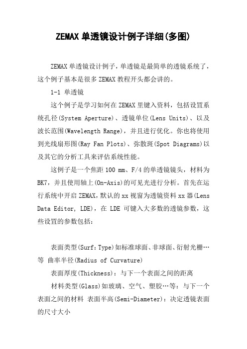
ZEMAX单透镜设计例子详细(多图)ZEMAX单透镜设计例子,单透镜是最简单的透镜系统了,这个例子基本是很多ZEMAX教程开头都会讲的。
1-1 单透镜这个例子是学习如何在ZEMAX里键入资料,包括设罝系统孔径(System Aperture)、透镜单位(Lens Units)、以及波长范围(Wavelength Range),并且进行优化。
你也将使用到光线扇形图(Ray Fan Plots)、弥散斑(Spot Diagrams)以及其它的分析工具来评估系统性能。
这例子是一个焦距100 mm、F/4的单透镜镜头,材料为BK7,并且使用轴上(On-Axis)的可见光进行分析。
首先在运行系统中开启ZEMAX,默认的xx视窗为透镜资料xx器(Lens Data Editor, LDE),在LDE可键入大多数的透镜参数,这些设罝的参数包括:表面类型(Surf:Type)如标准球面、非球面、衍射光栅…等曲率半径(Radius of Curvature)表面厚度(Thickness):与下一个表面之间的距离材料类型(Glass)如玻璃、空气、塑胶…等:与下一个表面之间的材料表面半高(Semi-Diameter):决定透镜表面的尺寸大小上面几项是较常使用的参数,而在LDE后面的参数将搭配特殊的表面类型有不同的参数涵义。
1-2 设罝系统孔径首先设罝系统孔径以及透镜单位,这两者的设罝皆在按钮列中的「GEN」按钮里。
点击「GEN」或透过菜单的System->General来开启General的对话框。
点击孔径标签(Aperture Tab)。
因为我们要建立一个焦距100 mm、F/4的单透镜。
所以需要直径为25 mm的入瞳(Entrance Pupil),因此设罝:Aperture Type:Entrance Pupil Diameter Aperture Value:25 mm点击单位标签(Units Tab),并确认透镜单位为Millimeters。
zemax应用举例1-单透镜
8)单透镜还能更好吗? 单透镜还能更好吗?
方法二
优化结果
慧差几乎为零 系统成像质量几乎没有改变
8)单透镜还能更好吗? 单透镜还能更好吗?
方法三
优化结果
慧差几乎为0 慧差几乎为0,像散也非常小 点列图尺寸变大 此系统中主要存在球差和场曲两种像差
8)单透镜还能更好吗? 方法四 单透镜还能更好吗?
优化后单透镜结构参数
点列图 横向像差(光线扇形图) 横向像差(光线扇形图)
优化结果:MF=0.0659 优化结果: 存在问题:厚度太厚,不实用 存在问题:厚度太厚, ---增加厚度限制条件 ---增加厚度限制条件 单透镜中的可变参数:两个曲率半径, 单透镜中的可变参数:两个曲率半径, 两个厚度, 两个厚度,光阑位置 现在的可变参数:前曲率半径及透镜厚度, 现在的可变参数:前曲率半径及透镜厚度, 且厚度作用不大 如何改善? 如何改善? ---离焦 ---离焦 ---光阑位置可变 ---光阑位置可变
6)进一步优化
优化结果
Rear landscape
成像质量大大改善! 成像质量大大改善!
7)另外一种可替代的结构
Front landscape
8)单透镜还能更好吗? 单透镜还能更好吗?
方法一
优化结果
SPHA
1.079 33 72 RMS spot size 48 98
2.799
结论: 结论: 1、单透镜不能校正球差 2、优化特定的像差结果往往不理想
例子1 例子1
单透镜
1)设计要求: 设计要求: 入瞳直径: 入瞳直径:40mm F/# : F/10 材料:BK7 材料: 物距: 物距:无穷远 2w=100 波长: 波长:0.587um 光阑在系统第一面 要求在近轴焦点处系统有最好的RMS 要求在近轴焦点处系统有最好的RMS spot size
zemax自聚焦透镜设计[整理版]
zemax自聚焦透镜设计[整理版] 目录摘要 (I)Abstract............................................ II 绪论................................................. 1 1 自聚焦透镜简介..................................... 2 1.1自聚焦透镜 ..................................... 2 1.2 自聚焦透镜的特点 ............................... 2 1.3 自聚焦透镜的主要参数 ........................... 3 2 自聚焦透镜的应用................................... 5 2.1 聚焦和准直 ..................................... 5 2.2 光耦合 ......................................... 6 2.3 单透镜成像 ..................................... 7 2.4 自聚焦透镜阵列成像 ............................. 7 3 球面自聚焦透镜设计仿真............................. 9 3.1 确定透镜模型 ................................... 9 3.2 设置波长 (9)3.3数值孔径设定 .................................. 11 3.4 自聚焦透镜光路 ................................ 11 4 优化参数.......................................... 124.1光线相差分析 .................................. 12 4.2聚焦光斑分析 .................................. 14 4.3 3D模型 ....................................... 14 结束语.............................................. 15 致谢.............................................. 16 参考文献.. (17)摘要本文主要说明应用梯度折射率对光传播的影响分析设计自聚焦透镜(GRIN lens),自聚焦透镜主要应用于光纤传输系统中。
ZEMAX光学成像设计实例---ZEMAX基础实例-单透镜设计
第二章 基础实例设计ZEMAX基础实例 ‐ 单透镜设计引言• 在成像光学系统设计中,主要指的是透镜系统设计,当然也有一些反射系统或棱镜系统。
• 在透镜系统设计中,最基础、最简单的便是单透镜设计。
但我们不要小看这样的单透镜系统,因为它也代表了一个光学系统设计的完整流程。
麻雀虽小,五脏俱全!• 本节中,我们通过手把手的操作,为大家展示使用 ZEMAX 进行成像光学设计的完整流程。
使初学者快速领略到ZEMAX光学设计的风采,在轻松的设计中感受到光学设计的乐趣。
• 通过单透镜设计,可以使大家学习到Z EMAX 序列编辑器建模方法,光束大小设置方法,视场设置方法,变量的设罝方法,评价函数设置方法,优化方法,像差分析方法和提髙像质的像差平衡方法等,单透镜系统参数设计任何一个镜头,我们都必须有特定的要求,比如焦距,相对口径,视场,波长,材料,分辨率,渐晕,MTF等等,根据系统的简易程度客户给的要求也各不相同。
由于单透镜最简单的系统,要求也就很少。
本例中我们设计单透镜规格参数如下:EPD = 20mmF/#=10FFOV= 10 degreeWavelength 0.587umMaterial BK7Best RMS Spot Radius首先我们需要把知道的镜头的系统参数输入软件中,系统参数包括三部分:光束孔径大小,视场类型及大小,波长。
在这个单透镜的规格参数中,入瞳直径(EPD)为20mm,全视场(FFOV)为10度,波长0.587微米,分别如下说明。
1、点击System » General或点快捷按扭Gen打开通用设置对话框:入瞳直径即到还有其它像空间F 数互转换。
物空间数值直接定义物随光阑尺寸用这种类型本例中,我2、点击打开即用来直接确它几种光束孔(Image Space 值孔径(Object 物点发光角度寸漂移(Float B 型来计算入瞳我们只需选择开视场对话框定进入系统光孔径定义类型e F/#),用于t Space NA),来约束进入系By Stop Size),瞳的大小。
ZEMAX光学设计第02讲ZEMAX实例:单透镜设计
球差
最小模糊圈 近轴焦点
横向像差 纵向像差 球差存在时最清楚面不在近轴焦点处!
光学像差 分类
•几何像差(单色像差)
–起源于非近轴光线的聚焦
• 球差 (spherical aberration) • 彗差 (coma) • 像散 (astigmatism) • 场曲 (field curvature) • 畸变 (distortion)
•色像差 Chromatic aberration
–起源于透镜折射率随波长改变,因此不同颜色聚焦 在不同位置
像差的起源
• 球差 (spherical aberration) • 彗差 (coma) • 像散 (astigmatism) • 场曲 (field curvature) • 畸变 (distortion)
ZEMAX光学设计 (第2讲)
Optical Design & ZEMAX
ZEMAX实例:单透镜设计
1.设计流程
系统参数输入 初始结构创建 优化变量设置 评价目标函数设置
像质分析 系统改进提高
再优化
2.单透镜设计实例
(1)LDE 透镜数据编辑
(2)孔径、视场、波长参数输入
3.球差
longitudinal aberrations
像差的起源
其他五种像差
• 统称为几何像差 • 在后面一一描述
球差
慧差
像散
场曲
畸变
H. Gross ed., Handbook of Optical Systems, Ch29.4, Wiley-VCH (2007)
像差的起源
• 另一种常见的像差表示法Zernike多项式
垂直倾斜
45°像散
- 1、下载文档前请自行甄别文档内容的完整性,平台不提供额外的编辑、内容补充、找答案等附加服务。
- 2、"仅部分预览"的文档,不可在线预览部分如存在完整性等问题,可反馈申请退款(可完整预览的文档不适用该条件!)。
- 3、如文档侵犯您的权益,请联系客服反馈,我们会尽快为您处理(人工客服工作时间:9:00-18:30)。
附录 D 术语表 Lateral Color: Chromatic aberration associated with the chief ray. Magnification: Ratio of image height to object height. Marginal Ray: Ray from the axial object point to the rim of the entrance pupil. Merit Function: A number that summarizes the state of optimization of an imaging system. The lower the number, the better the optimization. Modulation Transfer Function (MTF): A measure of image contrast as a function of spatial frequency. Null Lens: A refractive or reflective optical system interposed between a test point and an aspheric mirror in a radius of curvature test configuration. Compensates for the spherical aberration associated with the normals to the mirror surface. Numerical Aperture: Defines the light collection capability of an optical system in object space for a finite object distance. Optical Path Length: The actual path length multiplied by the refractive index within that path. Optical Path Difference: The separation between an aberrated wavefront and a reference sphere at some point in the exit pupil. Optical Power: The reciprocal of focal length. Principal Plane(s): An optical imaging system has a pair of principal planes (front and rear). These planes, along with a knowledge of focal point locations, can represent the first order imaging properties of the system (no matter how complicated that system may be). The image point location of any object point can be determined via simple graphical ray tracing techniques. Paraxial Plane: For an optical imaging system,trace rays which lie close to the optical axis through the system for a given axial object point. The convergence point of such rays in image space defines the location of the paraxial
342
透镜设计导论
附录 D 术语表
Aberration: An ideal monochromatic point image is formed from a spherical converging wavefront. Wavefronts that are not spherical are considered aberrated as are the images they form. The common aberrations affecting the point image are spherical aberration,coma,and astigmatism. Aberrations that effect image point location axially and laterally also occur. These are field curvature and distortion. Abbe number: A number which quantifies the dispersive nature of glass. Achromat: A lens composed of two elements with different dispersive properties which correct primary axial color. Airy Disk: In geometric optics,an ideal lens forms a point image of a point object. When physical optics is taken into account,the point object is imaged by an ideal lens as a finite-sized circular disk (assuming a circular aperture). Aplanat: An optical imaging system that has no spherical aberration or coma. Aspheric: An optical surface that is not spherical in shape. Axial Color: The refractive index of glass is wavelength dependent so glass lenses form images of different colors at different points along the optical axis. Back Image Distance: The separation between the last optical surface in an imaging system and the paraxial image plane. Chief Ray: The ray from the maximum field position that passes through the center of the stop. Conic Constant: A number that defines an optical surface's departure from a spherical surface. Corrector Plate: A refractive optical element that eliminates spherical aberration in an imaging system. Curvature: The reciprocal of the radius of curvature for an optical surface. Defocus: The axial separation between the paraxial image plane and a different plane of observation. Depth of Focus: Roughly the axial range over which the image appears unchanged to an observer. Dispersion: Variation of the refractive index with wavelength. Diffraction Limited: The performance of the imaging system is limited not by geometric aberrations, but by the physical optics phenomenon of diffraction. Effective Focal Length: The separation between the rear principal plane and the paraxial image plane. Entrance Pupil: Image of stop formed by optics to the left of stop. Exit Pupil: Image of stop formed by optics to the right of stop. Field Angle: The angle an object point makes with respect to the optical axis as determined from the vertex of the entrance pupil. Field Flattener: Usually a negative element close to the image plane that reduces or eliminates Petzval field curvature. Field of View: Object scene that fits within defined image plane format. Format: That which physically limits the image scene extent in the image plane, e.g., the size of a CCD chip. f-number: The ratio of the effective focal length to the entrance pupil diameter for an object at infinity.